1988 PONTIAC FIERO wiring
[x] Cancel search: wiringPage 1475 of 1825
EXTERIOR LlGHTS
(Continued from previous page)
Park/MarkerflaIl/License UgMs
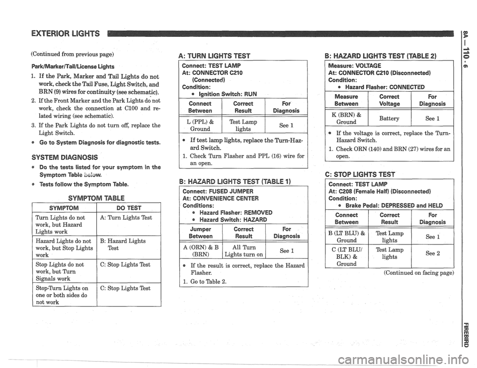
1. If the Park, Marker and Tail Lights do not
work, cheek the Tail Fuse, Light Switch, and
BRN (9) wires for continuity (see schematic).
2. If the Front Marker and the Park Lights dd not
work, check the connection at 6100 and re-
lated wiring (see schematic).
3. If the Park Lights do not turn off, replace the
Light Switch.
s Go to System Diagnosis for diagnostic tests.
@ Do the tests listed for your symptom in the
Symptom
Able bezaw.
@ Tests follow the Symptom Table.
SYMPTOM arABhE
A: TURN LIGHTS TEST
SYMPTOM
Turn Lights do not
work, but Hazard
Lights work
Hazard Lights do not
work, but Stop Lights
work
Stop Lights do not
work, but Turn
Signals work
Stop-Turn Lights on
one or both sides do
not work
B: HAZARD LIGHTS TEST (TABLE 2)
DO TEST
A: Turn Lights Test
B: Hazard Lights
Test
6: Stop Lights Test
6: Stop Lights Test
Connect: TEST LAMP
At: CONNECTOR C210
(Connected)
Condition:
Ignition Switch: RUN
o If the result is correct, replace the Hazard
Flasher.
1. Go to Table 2.
B: HAZARD LIGHTS TEST (TABLE 1)
Connect: FUSED JUMPER
At: CONVENIENCE
CENTER
Conditions:
r Hazard Flasher: REMOVED
Hazard Switch:
HAZARD
Measure: VOLTAGE
At: CONNECTOR 621 0 (Disconneded)
Condition:
Hazard Flasher: CONNECTED
For
Diagnosis
See 1
Connect
Between
L (PPL) &
Ground
I Measure ( Correct ( For
e If test lamp lights, replace the
ard Switch.
1. Check Turn Flasher and PPE (16) wire for
an open.
Correct
Result
Test Lamp
lights
For
Diagnosis
See 1
Jumper
Between
A (QRN) & B
(BRN)
Between I Voltage I Diagnosis
Correct Result
All Turn
Lights turn on
( If the voltage is correct, replace the Turn- I
(BRN) &
Ground
Hazard Switch.
1. Check ORN (140) and BRN (27) wires for an
open.
6: STOP LIGHTS TEST
At: 6208 (Fernale Half) (Disconnected)
Condition:
Brake Pedal: DEPRESSED and HELD
Battery See 1
Connect
Behvveen
I CEKyy 1 Test Lamp
lights I See 2 I
B (LT BLU) &
Ground
I Ground I I I
Correct
Result
(Continued on facing page)
For
Diagnosis
Test Lamp
lights See 1
Page 1476 of 1825
(Continued from facing page)
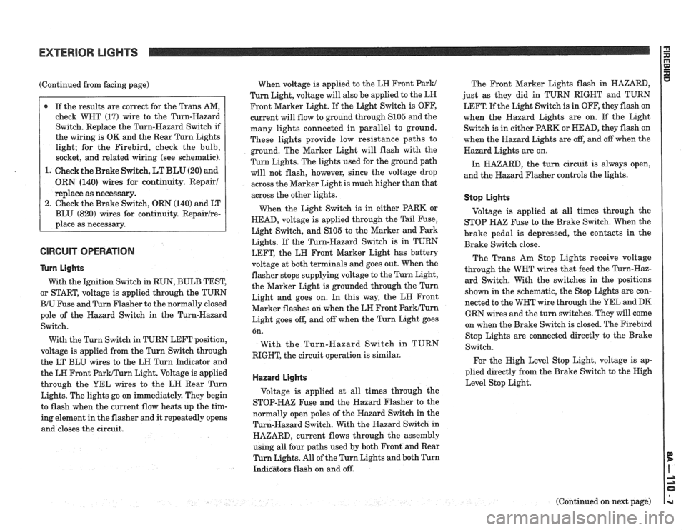
@ If the results are correct for the Trans AM,
check WHT (17) wire to the Turn-Hazard
Switch. Replace the Turn-Hazard Switch if
the wiring is OK and the Rear Turn Lights
light; for the Firebird, check the bulb,
socket, and related wiring (see schematic).
1. Check the Brake Switch,
LT BLU (20) and
ORN (140) wires for continuity. Repair1
replace as necessary.
2. Check the Brake Switch, ORN (140) and LT
BLU (820) wires for continuity.
Repairlre-
place as necessary.
GlRGUlT OPERATION
Turn Lights
With the Ignition Switch in RUN, BULB TEST,
or START, voltage is applied through the TURN
BIU Fuse and Turn Flasher to the normally closed
pole of the Hazard Switch in the Turn-Hazard
Switch.
With the Turn Switch in TURN LEFT position,
voltage is applied from the Turn Switch through
the LT BLU wires to the LH Turn Indicator and
the LH Front
ParWTurn Light. Voltage is applied
through the YEL wires to the LH Rear Turn
Lights. The lights go on immediately. They begin
to flash when the current flow heats up the tim-
ing element in the flasher and it repeatedly opens
and closes the circuit. When
voltage is applied to the LH Front
Park1
Turn Light, voltage will also be applied to the LH
Front Marker Light. If the Light Switch is OFF,
current will flow to ground through
S105 and the
many lights connected in parallel to ground.
These lights provide low resistance paths to
ground. The Marker Light will flash with the
Turn Lights. The lights used for the ground path
will not flash, however, since the voltage drop
across the Marker Light is much higher than that
across the other lights.
When the Light Switch is in either PARK or
HEAD, voltage is applied through the Tail Fuse,
Light Switch, and
S105 to the Marker and Park
Lights. If the Turn-Hazard Switch is in TURN
LEFT, the LH Front Marker Light has battery
voltage at both terminals and goes out. When the
flasher stops supplying voltage to the Turn Light,
the Marker Light is grounded through the Turn
Light and goes on. In this way, the LN Front
Marker flashes on when the LH Front
ParkITurn
Light goes off, and off when the Turn Light goes The
Front Marker Lights flash in HAZARD,
just as they did in TURN RIGHT and TURN
LEFT. If the Light Switch is in OFF, they flash on
when the Hazard Lights are on. If the Light
Switch is in either PARK or HEAD, they flash on
when the Hazard Lights are off, and off when the
Hazard Lights are on.
In HAZARD, the turn circuit is always open,
and the Hazard Flasher controls the lights.
Stop Lights
Voltage is applied at all times through the
STOP
HA% Fuse to the Brake Switch. When the
brake pedal is depressed, the contacts in the
Brake Switch close.
The Trans Am Stop Lights receive voltage
through the WHT wires that feed the Turn-Haz-
ard Switch. With the switches in the positions
shown in the schematic, the Stop Lights are con-
nected to the WHT wire through the YEL and DK
GRN wires and the turn switches. They will come
on when the Brake Switch is closed. The
Firebird on.
With
RIGHT, Stop
Lights are connected directly to the Brake
the Turn-Hazard Switch in TURN
Switch.
the circuit operation is similar.
For the High Level Stop Light, voltage is ap-
plied directly from the Brake Switch to the Nigh
Hazard Lights Level Stop Light.
Voltage is applied at all times through the
STOP-HAZ Fuse and the Hazard Flasher to the
normally open poles of the Hazard Switch in the
Turn-Hazard Switch. With the Hazard Switch in
HAZARD, current flows through the assembly
using all four paths used by both Front and Rear
Turn Lights. All of the Turn Lights and both Turn
Indicators flash on and off.
(Continued on next page)
Page 1483 of 1825
EXTERIOR LIGHTS WITH LAMP MONITOR I:
TROUBLESHOOTING HINTS
r Try the follovving checks before doing the
Systern Diagnosis .
1 . If neither the Turn Lights nor the Back Up
Lights work. check the TURN
BIU Fuse .
2 . If neither the Stop Lights nor the Hazard
Lights work. check the STOP-HAZ Fuse
.
3 . If only one light does not operate. check bulb.
socket. and related wiring (see schematic)
.
4 . If one of the Turn Indicators goes on when the
Park Lights are turned on. check the Front
Turn Light on that side
.
5 . For any of the following symptoms. replace the
Turn-Hazard Switch:
Some Turn Lights work and all Hazard
Lights work
.
@ Some Hazard Lights work and all Turn
Lights work
.
Hazard Lights do not turn off .
6 . If the Turn Lights stay on (do not flash) in both
TURN LEFT and TURN RIGHT. replace the
Turn Flasher
.
7 . If the Hazard Lights stay on (do not flash) in
HAZARD. but the Stop Lights go off normally.
replace the Hazard Flasher
.
8 . If no Park. Tail. or License Lights work.
check the Light Switch. and the
ORNIBLK
(240) and BRN (9) wires for an open (see
schematic)
.
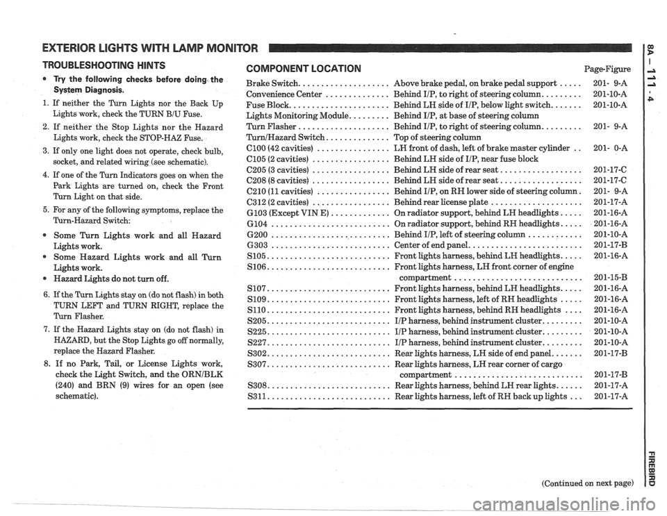
COMPONENT LOCATION Page-Figure
..... Brake Switch .................... Above brake pedal. on brake pedal support 201- 9-A
......... Convenience
Center .............. Behind IIP. to right of steering column 201-10-A
....... Fuse
Block ...................... Behind LH side of IIP. below light switch 201-10-A
Lights Monitoring Module
......... Behind IIP. at base of steering column
......... Turn Flasher .................... Behind IIP. to right of steering column 201-
9-A
TurnIHazard Switch .............. Top of steering column
.. ClOO (42 cavities) ................ LW front of dash. left of brake master cylinder 201- 0-A
................. C105 (2 cavities) Behind
LH side of IIP. near fuse block
.................. 6205 (3 cavities) ................. Behind LH side of rear seat 201-17-6
.................. ................. C208 (8 cavities) Behind LR side of rear seat 201-17-C
. C210 (11 cavities) ................ Behind IIP. on RH lower side of steering column 201-
9-A
.................... C312 (2 cavities) ................. Behind rear license plate 201-17-A
..... ............. 6103
(Except VIN E) On
radiator support. behind LH headlights 201-16-A
..... .......................... 6104 On
radiator support. behind RH headlights 201-16-A
............ .......................... 6200 Behind IIP. left of steering column 201-10-A
......................... .......................... 6303 Center of end panel 201-17-B
..... ........................... S105 Front lights harness. behind LH headlights 201-16-A
S106
........................... Front lights harness. LH front corner of engine
............................ compartment 201-15-B
..... ........................... S107 Front lights harness. behind LH headlights 201-16-A
..... S109 ........................... Front lights harness. left of RH headlights 201-16-A
.... S110 ........................... Front lights
harness. behind RH headlights 201-16-A
......... S205 ........................... IIP harness. behind
instrument cluster 201-10-A
......... S225 ........................... I/P harness. behind instrument cluster 201-10-A
......... S227 ........................... IIP harness. behind instrument cluster 201-10-A
....... S302 ........................... Rear lights harness. LH side of end panel 201-17-B
S307
........................... Rear lights harness. LH rear corner of cargo
............................ compartment 201-17-B
...... S308 ........................... Rear lights harness. behind LH rear lights 201-17-A
S311
........................... Rear lights harness. left of RW back up lights ... 201-17-A
Page 1493 of 1825
TROUBLESHOOTING HINTS
* Try the following checks.
Check
GTSY Fuse if none of the Interior Lights
operate.
DomeIReadinglCourtesy Lights
1. If the PanelIInterior Light Control does not op-
erate the Interior lights but the lights turn on
with any door open, check the Light Switch,
WBT (156) and BLK (150) wires for continuity
(see schematic).
2. If the Interior Lights do not come on with
only one door open, check the
WNT (156)
wire and suspect Door Jamb Switch for con-
tinuity.
Repairlreplace as necessary.
3. If the Dome Light comes on but the Reading
Light(s) do not, repairlreplace the Reading
Light(s) as necessary.
4. If the Dome and Reading Lights do not light
but the
RN and LII Courtesy Lights do,
check connection at
C206 and related wiring
(see schematic).
5. If the Dome Lights do not light when the
Panel Interior Light Control is turned to ON
but do light with any door open, check con-
nection at 6206
and related wiring for con-
tinuity (see schematic).
6. If the RN and LN Courtesy Lights do not
light with any door open but do light when
the Panel Interior Light Control is turned
ON, check related wiring for continuity (see
schematic).
7. If only one light does not operate, check bulb,
socket and related wiring (see schematic).
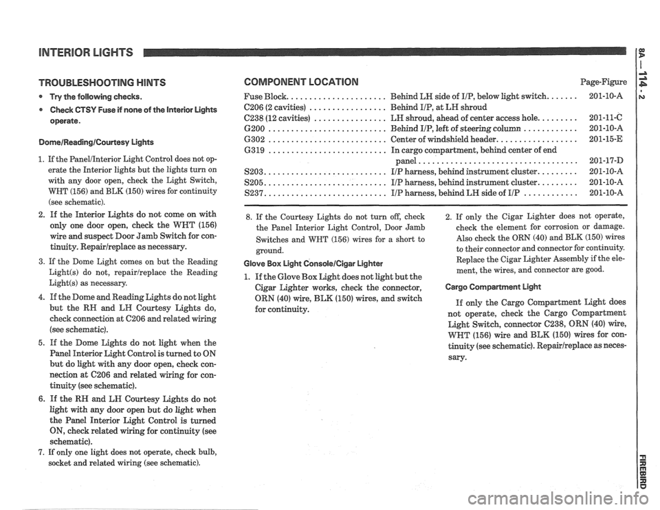
COMPONENT LOCATION Page-Figure
..................... Fuse Block. Behind
LN side of IIP, below light switch. ...... 201-10-A
................. C206 (2 cavities) Behd IIP, at LH shroud
................ C238 (12 cavities) LH shroud, ahead of center access hole. ........ 201-11-C
.......................... ............ 6200 Behind IIP, left of steering column 201-10-A
.......................... ................. 6302 Center of windshield header. 201-15-E
.......................... 63 19 In cargo compartment, behind center of end
................................... panel 201-17-D
.......................... S203. IIP harness, behind instrument cluster. ........ 201-10-A
.......................... S205. IIP harness, behind instrument cluster. ........ 201-10-A
.......................... ............ S237. I/P harness, behind LH side of IIP 201-10-A
8. If the Courtesy Lights do not turn off, check
the Panel Interior Light Control, Door Jamb
Switches and
WBT (156) wires for a short to
ground.
Glove Box Light GonsoleICigar Lighter
1. If the Glove Box Light does not light but the
Cigar Lighter works, check the connector,
ORN (40) wire,
BLK (150) wires, and switch
for continuity. 2. If
only the Cigar Lighter does not operate,
check the element for corrosion or damage.
Also check the ORN (40) and BLK (150) wires
to their connector and connector for continuity.
Replace the Cigar Lighter
Assembly if the ele-
ment, the wires, and connector are good.
Cargo Compartment EIgM
If only the Cargo Coqartment Light does
not operate, check the Cargo
Coqartment
Light Switch, connector 6238, ORN (40) wire,
WHT (156) wire and BLK (150) wires for con-
tinuity (see schematic).
Repairlreplace as neces-
sary-
Page 1508 of 1825
POWER DOOR LOCKS
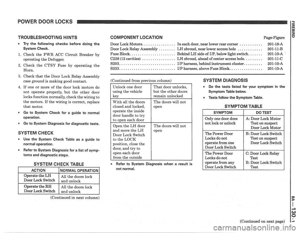
TROUBLESHOOTING HINTS
Try the following checks before doing the
Systern Check.
1. Check the PWR ACC Circuit Breaker by
operating the Defogger.
2. Check the CTSY Fuse by operating the
Horn.
3. Check that the Door Lock Relay Assembly
case ground is making good contact.
4. If one or more of the door lock motors do
not operate properly, but the other door
locks function normally, check the wiring to
the motors. If the wiring is correct, replace
that motor.
s Go to System Check for a guide to normal
operation.
Go to System Diagnosis for diagnostic tests.
SYSTEM CHECK
Use the System Check Table as a guide to
normal operation.
r Refer to System Diagnosis for a list of symp-
toms and diagnostic steps.
SYSTEM CHECK TABLE
COMPONENT LOCATION Page-Rgure
Door Lock Motors. ............... In each door, near lower rear corner ........... 201-18-A
Door Lock Relay Assembly
........ LN shroud, near lower access hole ............ 201-11-B
Fuse Block. ..................... Behind LH side of IIP, below light switch. ...... 201-10-A '
C238 (12 cavities) ................ LH shroud, ahead of center access hole. ........ 201-11-C
S203. .......................... IIP harness, behind instrument cluster. ........ 201-10-A
S233. .......................... IIP harness, above Fuse Block. ............... 201-10-A
(Continued from previous column)
Door Lock Switch
to the LOCK
position, close the SYSTEM DIAGNOSIS
r Do the tests listed for your symptom in the
Symptom Table below.
Tests
follow the Symptom Table.
SYMPTOM TABLE
Test on suspect
Door Lock Motor
The Power Door
B: Door Lock Switch
Locks do not Test on suspect
operate from one Door Lock Switch
Door Lock Switch
The Power Door
C: Door Lock Relay
Locks do not
I Test
r Refer to System Diagnosis when a result is operate from any B: Door Lock Switch
not normal. Door
Lock Switch Test
(Continued in next column)
(Continued on next page)
Page 1514 of 1825
THEFT DETERRENT SYSTEM: PASSKEY I i
A: LOCK CYLINDER AND HARNESS
TEST
1. Remove the hush panel under the steering
column. Disconnect the two-cavity connec-
tor in the wire leading into the steering col-
umn. Connect the male and female parts to
the mating connectors on the pigtails from
the 535628 Interrogator or equivalent.
2. Insert the customer's ignition key into the
Ignition Switch Lock Cylinder.
3. Press the On-Off switch on the 535628 Inter-
rogator to the ON position.
* The window above the Key Code Reader
indicates the electrical code for the key
(1 to
15) or
"En error.
Rotate the ignition lock cylinder while the
key is inserted to insure that the correct code
is read in all positions.
- If the code is correct in all positions, proceed
to step 5.
- If code is not correct in all positions, replace
the Lock Cylinder.
* If the window shows "E ", proceed to step 4.
4. Check the customer's ignition key by insert-
ing it in the Key Code Reader on the 535628
Interrogator.
If the Interrogator indicates
"EM, replace
the key with a spare or follow the procedures
under Key Replacement.
If Interrogator shows the electrical code
(1
to 15), replace the Lock Cylinder. (See pro-
cedure following Key Duplication Pro-
cedure). 5.
Set the Key Code Selector on the 535628
Interrogator to the same electrical code
determined in step 3. Turn the Ignition
Switch to START.
If engine starts, reconnect vehicle wiring
and check that the two-cavity connector at
the base of the steering column mates cor-
rectly.
If engine does not start, go to Test B,
Decoder Module Test.
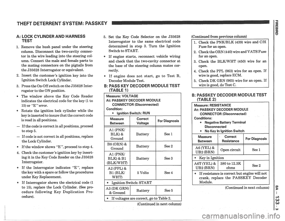
B: PASS KEY DECODER MODULE TEST
(TABLE
1 )
At: PASSKEY DECODER MODULE
CONNECTOR (Disconnected)
Condition:
1 . 1mition switch: START I
Ignition Switch: RUN
Continued from previous c
1. Check the PNKIBLK (439) wire and ClN
Fuse for an open.
2. Check the ORN (440) wire and VATS Fuse
for an open.
3. Check the
BLKIWT (450) wire for an
open.
4. Check the PPL (963) wire for an open.
If
wire is good, replace ECM.
5. Check DK GRN (965) wire for an open. If
wire is good, do Test C.
For Diagnosis
See 1
See 2
See 3
See 4
Measure
Between
A1 (PNKI
BLK) &
Ground
(ORN' &
Ground
A1 (PNKI
BLK)
& I31
(BLKIWNT)
A2 (PPL) &
Bl (BLKI
WNT)
B: PASSKEY DECODER MODULE TEST
Correct
Voltage
Battery
Battery
Battery
5 Volts
(TABLE 2)
Measure: RESISTANCE
At: PASSKEY DECODER MODULE
CONNECTOR (Disconnected)
Conditions: Negative Battery Terminal
Disconnected
r No lCev ln lainition Switch
Measure
- Correct For Diagnosis
Between Resistance
& open circuit
UB2 (BRN) See 1
crank,
replace the PASSKEY Decoder
Module.
-
(Continued in next column) A3 (DK GRN)
& Ground
I . If voltages are correct, go to Table 2.
(Continued in next column)
Battery See 5
Page 1551 of 1825
RADIO
(Continued from previous page)
1. Remove the Cancel Cam. Inspect the Slip
Rings on the Cancel Cam and the spring
loaded contacts on the Turn Signal
Switch. Replace as necessary. Incorrect
or missinglubricant on the Cam can cause
premature failure. Take care to keep lubri-
cant or any foreign material away from
the
LED'S and receptors as it will hinder
or prevent proper operation. The correct
lubricant is part no.
26002312.
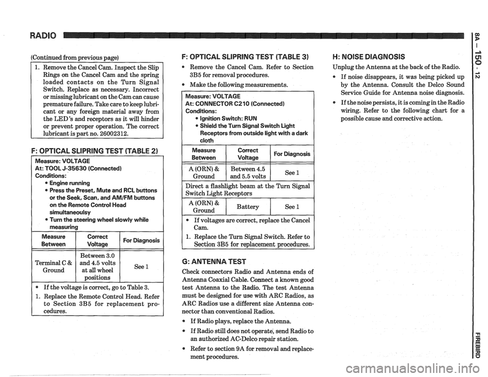
F: OPTICAL SLlPRlNG TEST (TABLE 2)
Measure: VOLTAGE
At: TOOL J-35630 (Connected)
Conditions:
@ Engine running
0 Press the Preset, Mute and RCL buttons
or the Seek, Scan, and
AMIFM buttons
on the Remote Control Head
sirnultaneoulsy
0 Turn the steering wheel slowly while
measuring
Measure
Correct I For Diagnosis I
I I Between 3.0 1 I Terminal C & and 4.5 volts
1 Ground 1 at all wheel
I 1 positions I I
I . If the voltage is correct, go to Table 3. (
1. Replace the Remote Control Head. Refer
to Section
3B5 for replacement pro-
cedures.
F: OPTICAL SLlPRllUG TEST (TABLE 3) H: NOlSE DIAGNOSIS
Remove the Cancel Cam. Refer to Section Unplug
the Antenna at the back of the Radio.
3B5 for removal procedures.
If noise disappears, it was being picked up
0 Make the following measurements.
by the Antenna. Consult the Delco Sound
Service Guide for Antenna noise diagnosis.
If the noise persists, it is coming in the Radio
wiring. Refer to the following chart for a
possible cause and corrective action.
At: CONNECTOR 6210 (Connected)
@ Ignition Switch: RUN
Shield the Turn Signal Switch Light
Receptors from outside light with a dark
1. Replace the Turn Signal Switch. Refer to
6: ANTENNA TEST
Check connectors Radio and Antenna ends of
Antenna Coaxial Cable. Connect a known good
test Antenna to the Radio. The test Antenna
must be designed for use
with ARC Radios, as
ARC Radios use a different size Antenna con-
nector than conventional Radios.
@ If Radio plays, replace the Antenna.
If Radio still does not operate, send Radio to
an authorized AC-Delco repair station.
Refer to section 9A for removal and replace-
ment procedures.
Page 1553 of 1825
RADIO I
(Continued from previous page) from back of Radio
If noise persists with replacement antenna, the
problem must be repaired at the source of noise
(generator, ignition system, accessory, etc.). See
Delco Manual for noise "Sniffing" procedures.
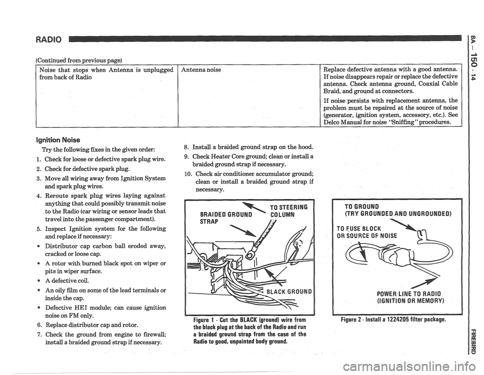
Ignition Noise
Trv the following. fixes in the piven order: 8. Install a braided ground strap on the hood. Replace
defective antenna with a good antenna.
If noise disappears repair or replace the defective
antenna. Check antenna ground, Coaxial Cable
Braid, and ground at connectors.
unplugged
- -
1. Check
for loose or defective spark plug wire.
2. Check for defective spark plug.
3. Move all wiring away from Ignition System
and spark plug wires. Antenna
noise
4. Reroute spark plug wires laying against
anything that could possibly transmit noise
to the Radio (car
g or sensor leads that
travel into the passenger compartment).
5. Inspect Ignition system for the following
and replace if necessary:
r Distributor cap carbon ball eroded away,
cracked or loose cap.
A rotor with burned black spot on wiper or
pits in wiper surface.
r A defective coil.
r An oily film on some of the lead terminals or
inside the cap.
Defective
WE1 module; can cause ignition
noise on
FM only.
6. Replace distributor cap and rotor.
9. Check Heater Core ground; clean or install a
braided ground strap if necessary.
10. Check air conditioner accumulator ground;
clean or install a braided ground strap if
necessarv.
TO STEERING
BRAIDED
GROUN GO LUMN
Figure 1 - Gut the BLACK (ground) wire from
the black plug
at the back of the Radio and run
7. Check the ground from engine to firewall, a braided ground strap from the ease of the
install a braided ground strap if necessary. Radio to good, unpainted body ground.
(TRY GROUNDED AND UNGROUNDED)
POWER LlNE TO RADIO
(IGNITION OR MEMORY)
Figure 2 - install a 1224205 filter package.