1988 PONTIAC FIERO wiring
[x] Cancel search: wiringPage 1384 of 1825
AIR CONDITIONING: COMPRESSOR CONTROLS
667, ELECTRONIC
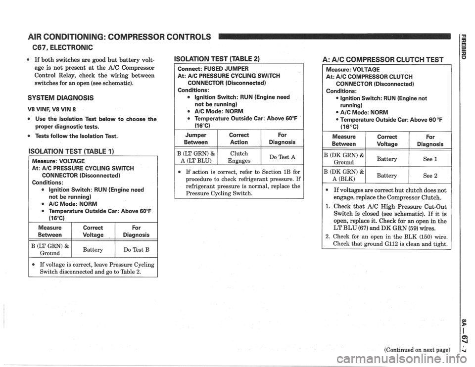
r If both switches are good but battery volt-
age is not present at the
A/C Compressor
Control Relay, check the wiring between
switches for an open (see schematic).
SYSTEM DlPaGNOSlS
V8 VINF, V8 VIN 8
s Use the Isolation Test below to choose the
proper diagnostic tests.
r Tests follow the Isolation Test.
lSOLATlON TEST (TABLE 2)
Connect: FUSED JUMPER
At:
A/C PRESSURE CYCLING SWITCH
CONNECTOR (Disconnected)
Conditions: Ignition Switch: RUN (Engine need
not be running)
Q NC Mode: NORM
Q Temperature Outside Car: Above 60°F
(1 6°C)
I Jumper I Correct I For
lSOLATlOlU TEST (TABLE 1)
I Measure: VOLTAGE
AIC Mode:
NORM
@ Temperature Outside Car: Above 60°F
(1 6°C)
At:
AIC PRESSURE
CYCLING SWITCH
CONNECTOR (Disconnected)
Conditions:
lgnition Switch: RUN (Engine need
not be running) Between
B (LT GRN) &
A (LT
BLU)
If action is correct, refer to Section 1B for
procedure to check refrigerant pressure. If
refrigerant pressure is
normal, replace the
I (zz) & I Battery I Do Test B I
Measure
Between
A: AIC COMPRESSOR CLUTCH TEST
Action
Clutch
Engages
Diagnosis
Do Test A
Correct
Voltage
.
If voltage is correct, leave Pressure Cycling
Switch disconnected and go to Table
2.
Measure: VOLTAGE
At:
A/C COMPRESSOR CLUTCH
CONNECTOR (Disconnected)
Conditions:
lgnition Switch: RUN (Engine not
running)
0 A/C Mode: NORM
Temperature Outside Car: Above
60°F
(16°C)
For
Diagnosis
(Continued on next page)
Measure
Betvveen
B (DK GRN) &
Ground
B (DK GRN) &
A (BLK)
Q If voltages are correct but clutch does not
engage, replace the Compressor Clutch.
1. Check that A/C Nigh Pressure Cut-Out
Switch is closed (see schematic).
If it is
open, replace it. Check for
an open in the
LT BLU (67) and DK GRN (59) wires.
2. Check for an open in the BLK (150) wire.
Check that ground 6112 is clean and tight.
Correct
\joltage
Battery
Battelr
For
Diagnosis
See 1
See 2
Page 1409 of 1825
INSTRUMENT PANEL: GAGES CLUSTER I P
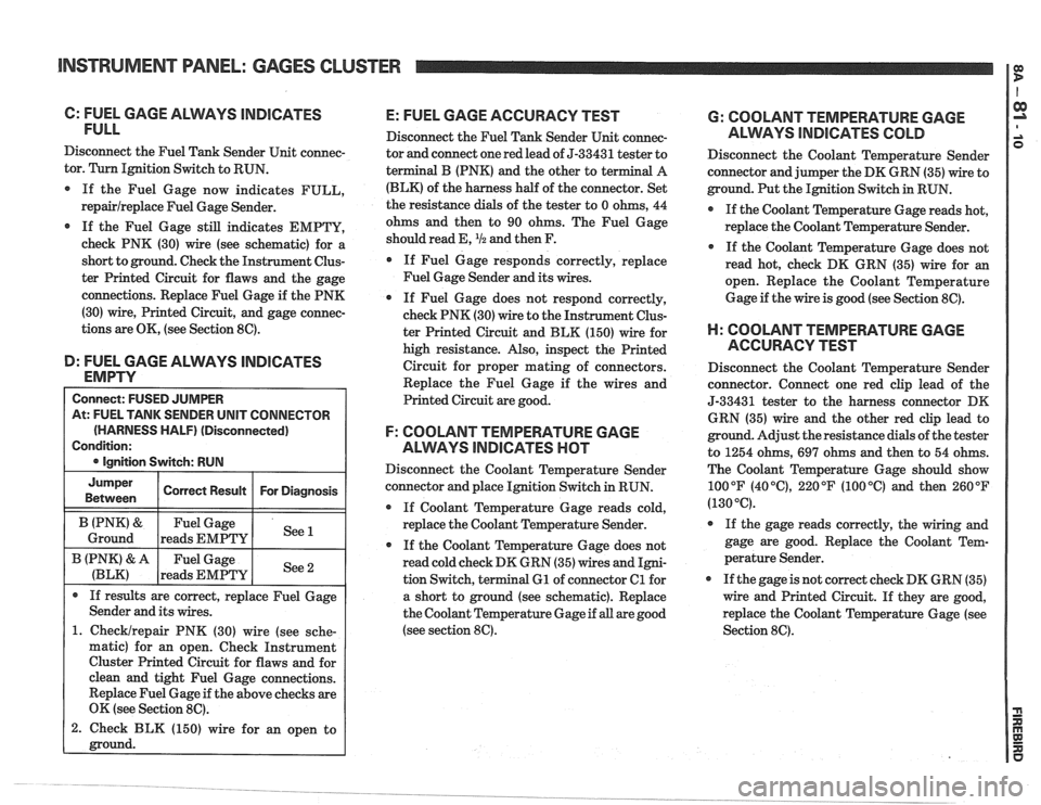
C: FUEL GAGE ALMYS lNDlCPaTES
FULL
Disconnect the Fuel Tank Sender Unit connec-
tor. Turn Ignition Switch to RUN.
If the Fuel Gage now indicates FULL,
repairlreplace Fuel Gage Sender.
@ If the Fuel Gage still indicates EMPTY,
check PNK (30) wire (see schematic) for a
short to ground. Check the Instrument Clus-
ter Printed Circuit for flaws and the gage
connections. Replace Fuel Gage if the PNK
(30) wire, Printed Circuit, and gage connec-
tions are OK, (see Section 8C).
D: FUEL GAGE ALVVAYS lNDlCATES
EMPTY
At: FUEL TANK SENDER UNIT CONNECTOR
(HARNESS HALF)
(Disconnected)
1. Checklrepair PNK (30) wire (see sche-
matic) for an open. Check Instrument
Cluster Printed Circuit for flaws and for
clean and tight Fuel Gage connections.
Replace Fuel Gage if the above checks are
OK (see Section
8C).
2. Check BLK (150) wire for an open to
E: FUEL GAGE ACCURACY TEST
Disconnect the Fuel Tank Sender Unit connec-
tor and connect one red lead of
5-33431 tester to
terminal
B (PNK) and the other to te
(BLK) of the harness half of the connector. Set
the resistance dials of the tester to 0 ohms, 44
ohms and then to 90 ohms. The Fuel Gage
should read E,
I12 and then F.
If Fuel Gage responds correctly, replace
Fuel Gage Sender and its wires.
0 If Fuel Gage does not respond correctly,
check PNK (30) wire to the Instrument Clus-
ter Printed Circuit and BLK (150) wire for
high resistance. Also, inspect the Printed
Circuit for proper mating of connectors.
Replace the Fuel Gage if the wires and
Printed Circuit are good.
F: COOLANT TEMPERATURE GAGE
ALWAYS
INDICATES HOT
Disconnect the Coolant Temperature Sender
connector and place Ignition Switch in RUN.
@ If Coolant Temperature Gage reads cold,
replace the Coolant Temperature Sender.
0 If the Coolant Temperature Gage does not
read cold check DK GRN (35) wires and Igni-
tion Switch, terminal
61 of connector Cl for
a short to ground (see schematic). Replace
the Coolant Temperature Gage if
all are good
(see section
8C).
6: COOLANT TEMPERATURE GAGE
ALWYS INDICATES COLD
Disconnect the Coolant Temperature Sender
connector and jumper the DK GRN (35) wire to
ground. Put the Ignition Switch in RUN.
0 If the Coolant Temperature Gage reads hot,
replace the Coolant Temperature Sender.
If the Coolant Temperature Gage does not
read hot, check DK GRN (35) wire for
an
open. Replace the Coolant Temperature
Gage if the wire is good (see Section
8C).
H: COOLANT TEMPERATURE GAGE
ACCURACY TEST
Disconnect the Coolant Temperature Sender
connector. Connect one red clip lead of the
5-33431 tester to the harness connector DK
GRN (35) wire and the other red clip lead to
ground. Adjust the resistance dials of the tester
to 1254 ohms,
697 ohms and then to 54 ohms.
The Coolant Temperature Gage should show
100°F
(40°C), 220°F (100°C) and then 260°F
(130°C).
If the gage reads correctly, the wiring and
gage are good. Replace the Coolant Tem-
perature Sender.
If the gage is not correct check DK GRN (35)
wire and Printed Circuit. If they are good,
replace the Coolant Temperature Gage (see
Section
8C).
Page 1427 of 1825
BNS'TWUMENT PANEL: DIGITAL CLUSTER a B
(Continued from previous gage)
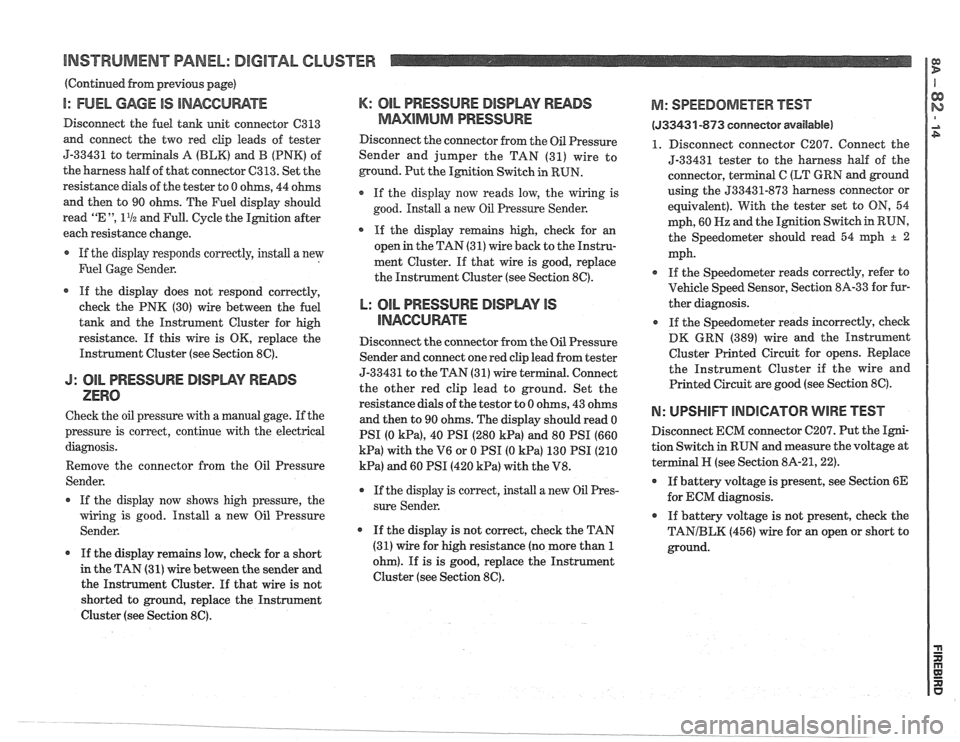
I: FUEL GAGE IS INACCUWTE
Disconnect the fuel tank unit connector C313
and connect the two red clip leads of tester
5-33431 to
terminals A (BLK) and B (PNK) of
the harness half of that connector
C313. Set the
resistance
dials of the tester to 0 ohms, 44 ohms
and then to 90 ohms. The Fuel display should
read
"E ", 11/2 and Full. Cycle the Ignition after
each resistance change.
If the display responds correctly, install a new
Fuel Gage Sender.
If the display does not respond correctly,
check the PNK (30) wire between the fuel
tank and the Instrument Cluster for high
resistance.
If this wire is OK, replace the
Instrument Cluster (see Section
8C).
J: OIL PRESSURE DISIDWY READS
ZERO
Check the oil pressure with a manual gage. If the
pressure is correct, continue with the electrical
diagnosis.
Remove the connector from the Oil Pressure
Sender.
If the display now shows high pressure, the
wiring is good. Install a new Oil Pressure
Sender.
If the display remains low, check for a short
in the TAN (31)
wire between the sender and
the Instrument Cluster. If that wire is not
shorted to ground, replace the Instrument
Cluster (see Section
8C).
K: OIL PRESSURE DISPWY RWDS
MMlMklM PRESSURE
Disconnect the connector from the Oil Pressure
Sender and jumper the TAN (31) wire to
ground. Put the Ignition Switch in RUN.
If the display now reads low, the wiring is
good. Install a new
Oil Pressure Sender.
* If the display remains high, check for an
open in the TAN (31) wire back to the Instru-
ment Cluster. If that wire is good, replace
the Instrument Cluster (see Section
8C).
L: OIL PRESSURE BlSPLAV IS
llUAGCll RATE
Disconnect the connector from the Oil Pressure
Sender and connect one red clip lead from tester
5-3343
1 to the TAN (3 1) wire terminal. Connect
the other red clip lead to ground. Set the
resistance dials of the
testor to 0 ohms, 43 ohms
and then to 90 ohms. The display should read 0
PSI (0
kPa), 40 PSI (280 kPa) and 80 PSI (660
kPa) with the V6 or 0 PSI (0 kPa) 130 PSI (210
kPa) and 60 PSI (420 kPa) with the V8.
r If the display is correct, install a new Oil Pres-
sure Sender.
If the display is not correct, check the TAN
(31) wire for high resistance (no more than
1
ohm). If is is good, replace the Instrument
Cluster (see Section
8C).
M: SPEEDOMETER BEST
(533431 -873 conneetor available)
1. Disconnect connector C207. Connect the
5-33431 tester to the harness
half of the
connector, terminal
C (LT GRN and ground
using the
533431-873 harness connector or
equivalent). With the tester set to
ON, 54
mph, 60
Hz and the Ignition Switch in RUN,
the Speedometer should read 54
qh + 2
mph.
If the Speedometer reads correctly, refer to
Vehicle Speed Sensor, Section
8A-33 for fur-
ther diagnosis.
If the Speedometer reads incorrectly, check
DK GRN (389) wire and the Instrument
Cluster Printed Circuit for opens. Replace
the Instrument Cluster if the wire and
Printed Circuit are good (see Section
8C).
N: UPSHIFT lNDlCATOR WIRE TEST
Disconnect ECM connector C207. Put the Igni-
tion Switch
in RUN and measure the voltage at
terminal
N (see Section 8A-21,221.
If battery voltage is present, see Section 6E
for ECM diagnosis.
If battery voltage is not present, check the
TANIBLK (456) wire for an open or short to
ground.
Page 1436 of 1825
DRIVER INFORMATION CENTER (DIC)
(Continued from facing page)
@ If both tests are good, replace the Washer
Fluid Level Switch.
1. Check the BLKIWHT (99) wire for an
open (see schematic).
2. Check the BLK (152) wire for an open (see
schematic).
6: WASHER FLUID LEVEL SHORTED
SwlTen TEST
Disconnect the Washer Fluid Level Switch Con-
nector
terminal A. Switch the Ignition to RUN
and observe the Low Washer Fluid Indicator
segment on windshield of the vehicle symbol on
the
me.
If the Low Washer Fluid segment is now off,
and Low Washer Fluid is not displayed,
replace the Washer Fluid Level Switch.
If the Low Washer Fluid segment lights, and
LOW
VirASHER FLUID is displayed, check
the
BLKIWWT (99) wire for a short to
ground.
B: LOW COOLANT PROBE CONNEC-
TOR TEST
If the Low Coolant message does not come on
and the indicator segment on the vehicle sym-
bol does not light with the coolant low, remove
the connector to the Low Coolant Probe. With
the Ignition in RUN the indicator
should oper-
ate after approximately
11 seconds.
If it does,
install a new Low Coolant Probe.
* If it does not, check YELIBLM wire to the
DIC Display for a short to ground. Install a
new DIC display if the wire is good.
E: LOW COOLANT PROBE RESISTANCE
TEST
If the LOW COOLANT message comes on and
the indicator segment on the vehicle symbol
lights with the engine coolant full, check the
resistance of the Low Coolant Probe and its
wire. Remove the connector from the probe and
measure the resistance to ground of the probe.
If the resistance is higher than 30,000 ohms,
instdl a new Low Coolant Probe.
If the probe
and its wiring are good, and the
display does not indicate properly, install a
new DIC.
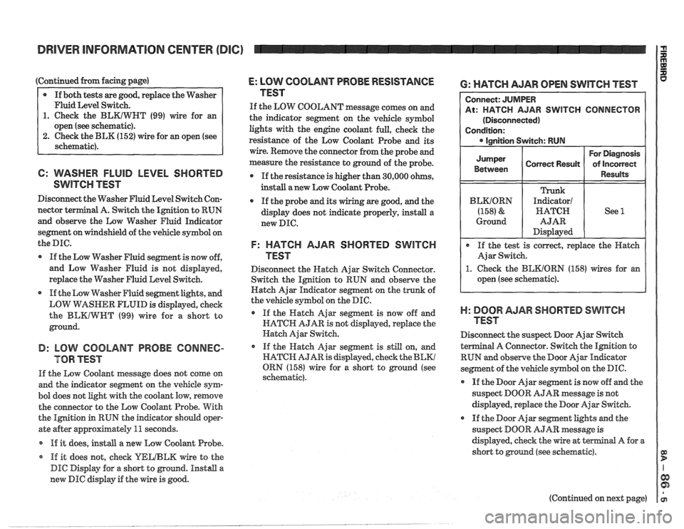
F: HATCH AJAR SHORTED SWITCH
TEST
Disconnect the Hatch Ajar Switch Connector.
Switch the Ignition to RUN and observe the
Hatch Ajar Indicator segment on the trunk of
the vehicle symbol on the DIC.
If the Hatch Ajar segment is now off and
HATCH AJAR is not displayed, replace the
Hatch Ajar Switch.
o If the Hatch Ajar segment is still on, and
HATCH AJAR is displayed, check the
BLKl
ORN (158) wire for a short to ground (see
schematic).
6: WATCH AJAR OPEN SWITCH TEST
R SWITCH CONNECTOR
1. Check the BEKIORN (158) wires for an
open (see schematic).
)-I: BOOR AJAR SHORTED SWITCH
TEST
Disconnect the suspect Door Ajar Switch
a1 A Connector. Switch the Ignition to
RUN and observe the Door Ajar
Indieator
segment of the vehicle symbol on the DIC.
@ If the Door Ajar segment is now off and the
suspect DOOR AJAR message is not
displayed, replace the Door Ajar Switch.
If the Door Ajar segment lights and the
suspect DOOR
AJAR message is
displayed, check the wire at
terminal A for a
short to ground (see schematic).
(Continued on next page)
Page 1451 of 1825
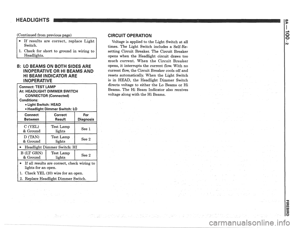
HEADLIGHTS
(Continued from previous page)
If results are correct, replace Light
Switch.
short to ground in wiring to
B: LO BEAMS ON BOTH SIDES ARE
INOPERATIVE OR HI BEAMS AND
Ell BEAM INDICATOR ARE
Connect: TEST LAMP
At: HEADLIGHT DIMMER SWITCH
CONNECTOR (Connected)
Conditions:
0 Light Switch: HEAD
0 Headlight Dimmer Switch: LO
Connect Correct For
0 If all results are correct, check wiring to
lights for an open.
1. Check YEL (10) wire for an open.
2. Replace Headlight Dimmer Switch.
CIRCUIT OPERATION
Voltage is applied to the Light Switch at all
times. The Light Switch includes a Self-Re-
setting Circuit Breaker. The Circuit Breaker
opens when the Headlight circuit draws too
much current. When the Circuit Breaker
opens, it interrupts the current flow. With no
current flow, the Circuit Breaker cools off and
resets automatically. When the Light Switch
is in
HEAD, the Headlight Dimmer Switch
directs voltage to either the Lo Beams or
Hi
Beams. The Hi Beam Indicator also receives
voltage along with the
Hi Beams.
Page 1459 of 1825
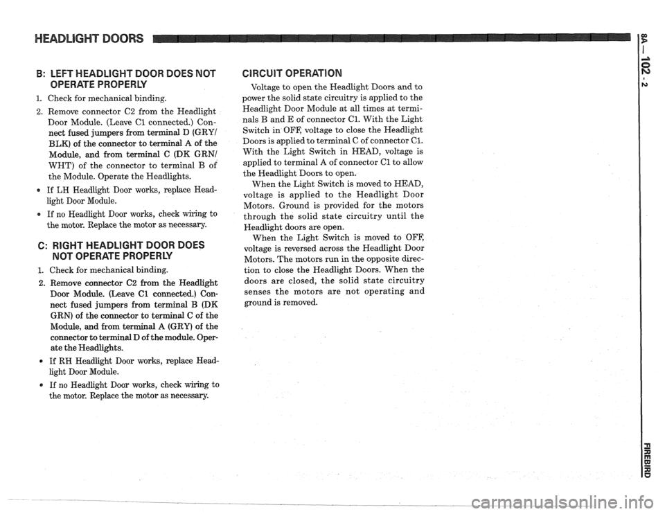
HEADLIGHT DOORS
B: LEFT HEADLIGHT DOOR DOES NOT
OPERATE PROPERLY
1. Check for mechanical binding.
2. Remove connector C2 from the Headlight
Door Module. (Leave
C1 connected.) Con-
nect fused jumpers from terminal D
(GRYI
BLK) of the connector to terminal A of the
Module, and from terminal C (DK GRNI
WHT) of the connector to terminal
B of
the Module. Operate the Headlights.
0 If LH Headlight Door works, replace Head-
light Door Module.
0 If no Headlight Door works, check wiring to
the motor. Replace the motor as necessary.
6: RIGHT HEADLIGHT DOOR DOES
NOT OPERATE PROPERLY
1. Check for mechanical binding.
2. Remove connector C2 from the Headlight
Door Module. (Leave
C1 connected.) Con-
nect fused jumpers from terminal B (DK
GRN) of the connector to terminal
C of the
Module, and from terminal
A (GRY) of the
connector to terminal D of the module. Oper-
ate the Headlights.
If RH Headlight Door works, replace Head-
light Door Module.
0 If no Headlight Door works, check wiring to
the motor. Replace the motor as necessary.
GlRGUlT OPERATION
Voltage to open the Headlight Doors and to
power the solid state circuitry is applied to the
Headlight Door Module at all times at termi-
nals
B and E of connector 61. With the Light
Switch in OFF, voltage to close the Headlight
Doors is applied to terminal C of connector
C1.
With the Light Switch in HEAD, voltage is
applied to terminal A of connector
C1 to allow
the Headlight Doors to open.
When the Light Switch is moved to HEAD,
voltage is applied to the Headlight Door
Motors. Ground is provided for the motors
through the solid state circuitry until the
Headlight doors are open.
When the Light Switch is moved to OFF,
voltage is reversed across the Headlight Door
Motors. The motors run in the opposite direc-
tion to close the Headlight Doors. When the
doors are closed, the solid state circuitry
senses the motors are not operating and
ground is removed.
Page 1463 of 1825
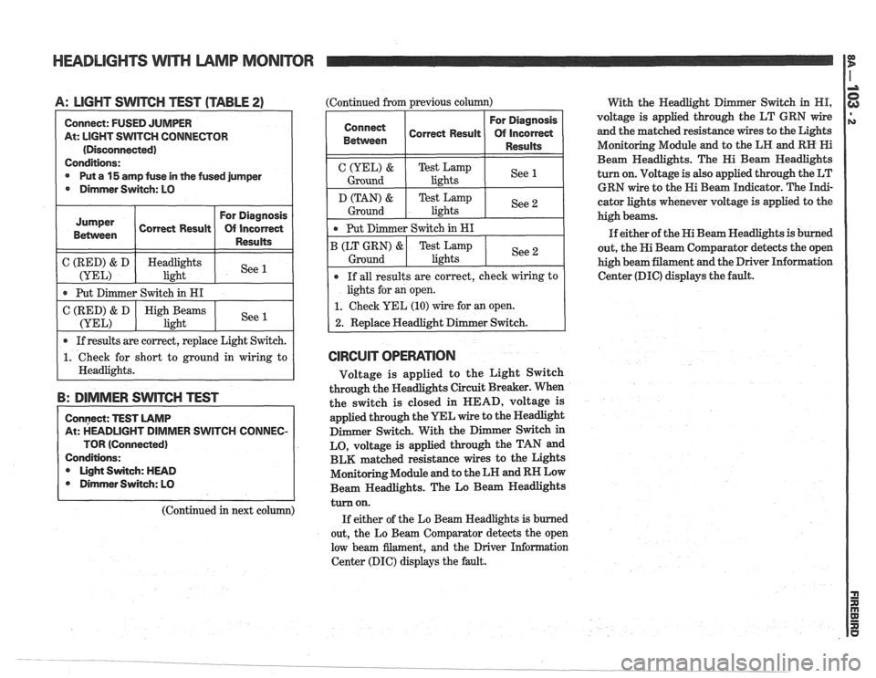
HEADLIGHTS WITH LAMP MONITOR
A: LIGHT SWITCH TEST (TABLE 2) (Continued from previous column)
With the Headlight D er
Switch in HI,
Connect: FUSED JUMPER
At: LIGHT
SWITCH CONNECTOR
(Disconnected)
Conditions:
@ Put a 15 amp fuse in the fused jumper
@ Dimmer Switch: LO
( C (RED) & D ( Headlights 1 See (YEL) light I
Jumper
Betvveen
I Put Dimmer Switch in HI I
Correct Result
I 0 If results are correct, replace Light Switch. I
For Diagnosis
Of incorrect
Results
C (RED) & D
(YEL)
1. Check for short to ground in wiring to
I Headlights.
B: DIMMER SWITCH TEST
High Beams
light
Connect: TEST LAMP
At: HEADLIGHT DIMMER SWITCH
COIUNEC-
TOR (Connected)
Conditions: Light Switch: HEAD
@ Dirnmer Switch: LO
See 1
(Continued in next column)
For Diagnosis
Correct
~esu~t Of incorred
1 1 1 Resd% 1
C(YEL)& TestLamp
Ground lights See 1
Ground I
Put
Dimmer Switch in HI
B (LT GRN)
& Test Lamp
lights See 2 Ground
If all results are correct, check wiring to
lights for an open.
1. Check YEL (10) wire for an open.
2. Replace Headlight Dimmer Switch.
CIRCUIT OPERATION
Voltage is applied to the Light Switch
through the Headlights Circuit Breaker. When
the switch is closed in HEAD, voltage is
applied through the YEL wire to the Headlight
Dimmer Switch. With the
D
LO, voltage is applied through the TAN and
BLK matched resistance wires to the Lights
Monitoring Module and to the LH and RH Low
Beam Headlights. The Lo Beam Headlights
turn on.
If either of the Lo Beam Headlights is burned
out, the Lo Beam Comparator detects the open
low beam filament, and the Driver Information
Center (DIC) displays the fault. voltage
is applied through the
LT GRN wire
and the matched resistance wires to the Lights
Monitoring Module and to the LH and
RH Hi
Beam Headlights. The Hi Beam Headlights
turn on. Voltage is also applied through the LT
GRN wire to the Hi Beam
In&cator. The In&-
cator lights whenever voltage is applied to the
high beams.
If either of the Hi Beam Headlights
is burned
out, the Hi Beam Comparator detects the open
high beam filament and the Driver Information
Center (DIC) displays the fault.
Page 1474 of 1825
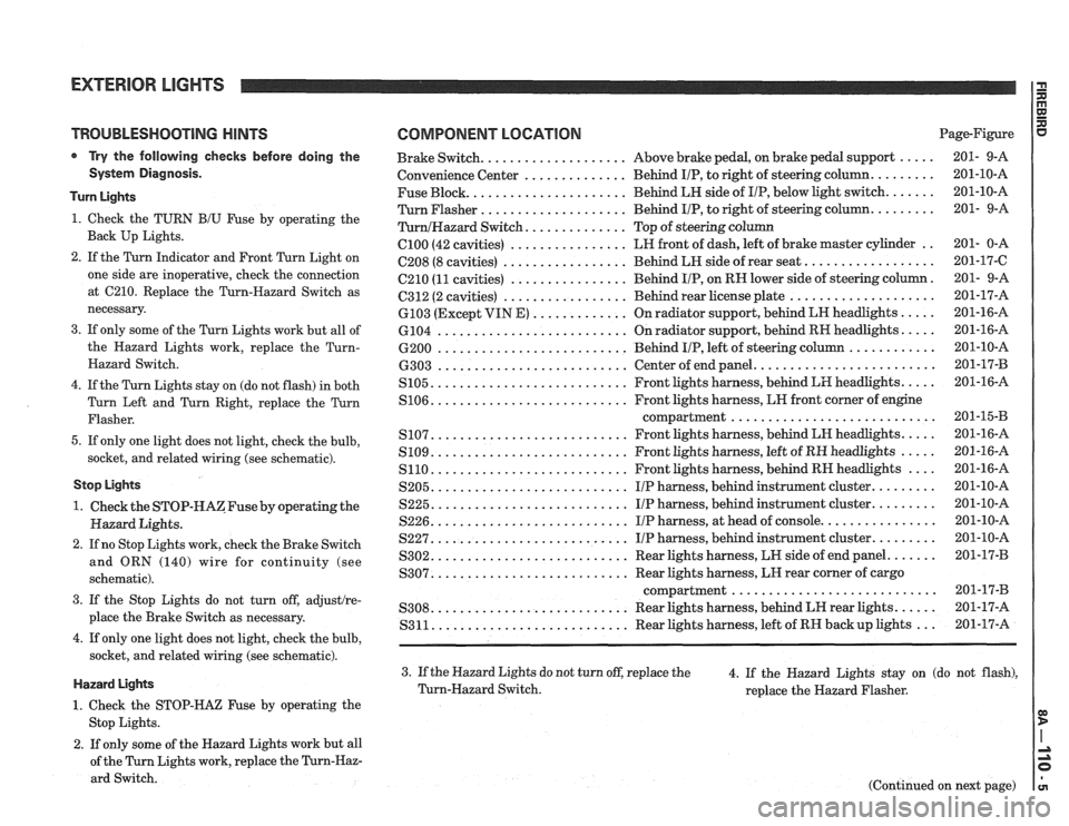
TROUBLESHOOTING HINTS
Try the following checks before doing the
System Diagnosis.
Turn Lights
1. Check the TURN B/U Fuse by operating the
Back Up Lights.
2. If the Turn Indicator and Front Turn Light on
one side are inoperative, check the connection
at
C210. Replace the Turn-Hazard Switch as
necessary.
3. If only some of the Turn Lights work but all of
the Hazard Lights work, replace the
Turn-
Hazard Switch.
4. If the Turn Lights stay on (do not flash) in both
Turn Left and Turn Right, replace the Turn
Flasher.
5. If only one light does not light, check the bulb,
socket, and related wiring (see schematic).
Stop Lights
1. Check the STOP-HAZFuse by operating the
Hazard Lights.
2. If no Stop Lights work, check the Brake Switch
and ORN (140) wire for continuity (see
schematic).
3. If the Stop Lights do not turn off, adjustlre-
place the Brake Switch as necessary.
4. If only one light does not light, check the bulb,
socket, and related wiring (see schematic).
Hazard Lights
1. Check the STOP-HAZ Fuse by operating the
Stop Lights.
2. If only some of the Hazard Lights work but all
of the Turn Lights work, replace the
Turn-Haz-
ard Switch.
COMPONENT LOCATION Page-Figure
................... ..... Brake Switch. Above
brake pedal, on brake pedal support 201- 9-A
.............. ........ Convenience
Center Behind IIP, to right of steering column. 201-10-A
Fuse Block.
..................... Behind LH side of IIP, below light switch. ...... 201-10-A
Turn Flasher
.................... Behind IIP, to right of steering column. ........ 201- 9-A
............. TurnlHazard Switch. Top of steering column
C100 (42 cavities) ................ LH front of dash, left of brake master cylinder .. 201- 0-A
................. ................. C208 (8 cavities) Behind LH side of rear seat. 201-17-C
C210
(11 cavities) ................ Behind IIP, on RN lower side of steering column. 201- 9-A
................. .................... 6312 (2 cavities) Behind rear license plate 201-17-A
............. ..... 6103 (Except VIN E) On radiator support, behind LN headlights 201-16-A
.......................... .... 6104
On radiator support, behind RH headlights. 201-16-A
.......................... ............ 6200 Behind IIP, left of steering column 201-10-A
........................ .......................... 6303 Center of end panel. 201-17-B
.......................... .... S105. Front lights harness, behind LH headlights. 201-16-A
.......................... S106. Front lights harness, LN front corner of engine
compartment..
.......................... 201-1543
.......................... .... S107. Front lights harness, behind LH headlights. 201-16-A
.......................... ..... S109. Front lights harness, left of RH headlights 201-16-A
S110. .......................... Front lights harness, behind RH headlights .... 201-16-A
S205. .......................... IIP harness, behind instrument cluster. ........ 201-10-A
S225. .......................... IIP harness, behind instrument cluster. ........ 201-10-A
S226. .......................... IIP harness, at head of console. ............... 201-10-A
S227. .......................... IIP harness, behind instrument cluster. ........ 201-10-A
S302. .......................... Rear lights harness, LW side of end panel. ...... 201-17-B
.......................... S307. Rear lights harness, LH rear corner of cargo
compartment..
.......................... 201-17-B
.......................... ..... S308. Rear lights harness, behind LH rear lights. 201-17-A
S311. .......................... Rear lights harness, left of RH backup lights ... 201-17-A
3. If the Hazard Lights do not turn off, replace the
4. If the Hazard Lights stay on (do not flash),
Turn-Hazard Switch.
replace the Hazard Flasher.
(Continued on next page)