1988 PONTIAC FIERO wiring
[x] Cancel search: wiringPage 1638 of 1825
WINDSHIELD WIPER SYSTEMS - F CARLINE BE -11
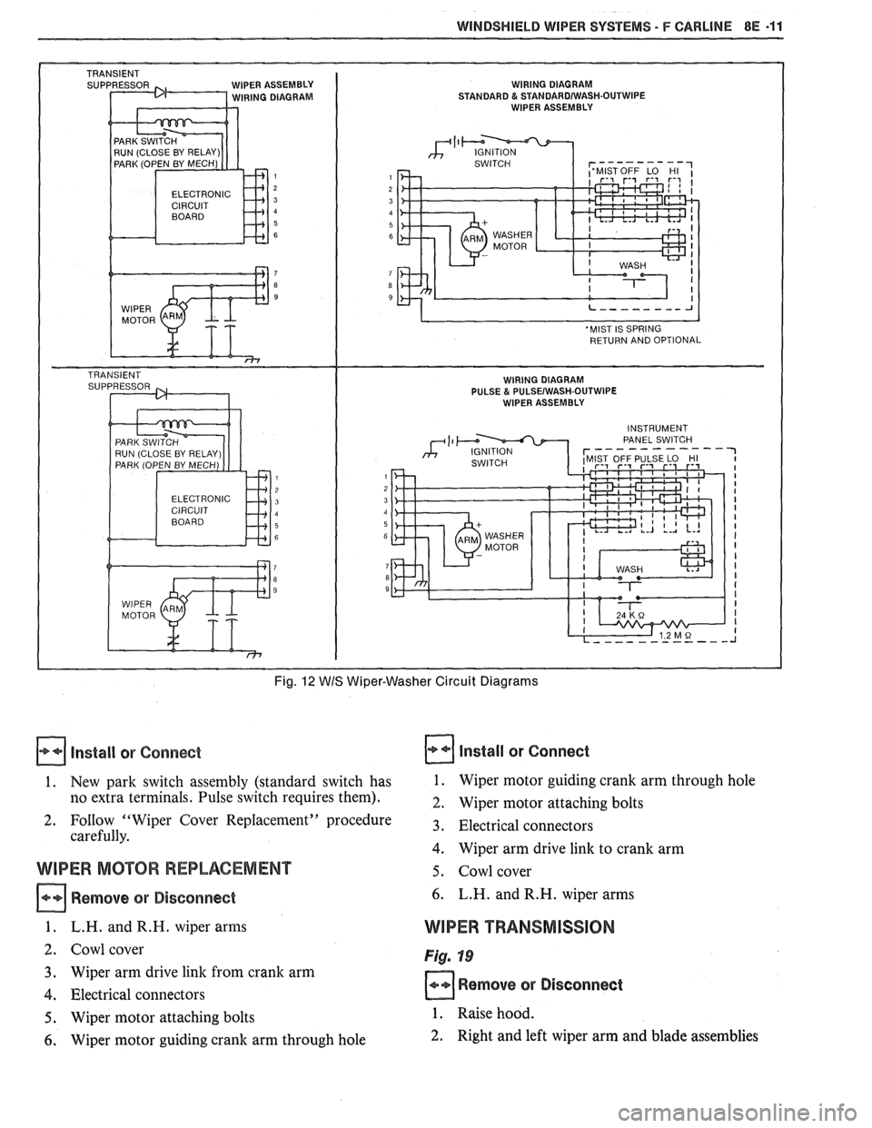
IPER ASSEMBLY WIRING DIAGRAM IRING DIAGRAM STANDARD & STANDARDIWASH.OUTWIPE WIPER ASSEMBLY
ELECTRONIC
Fig. 12 WIS Wiper-Washer Circuit Diagrams
Install or Connect
1. New park switch assembly (standard switch has
no extra terminals. Pulse switch requires them).
2. FoIlow "Wiper Cover Replacement" procedure
carefully.
WIPER MOTOR REPLACEMENT
Remove or Disconnect
1. L.H. andR.H. wiper arms
2. Cowl cover
3. Wiper arm drive link from crank arm
4. Electrical connectors
5. Wiper motor attaching bolts
6. Wiper motor guiding crank arm through hole
Install or Connect
1. Wiper motor guiding crank arm through hole
2. Wiper motor attaching bolts
3. Electrical connectors
4. Wiper arm drive link to crank arm
5. Cowl cover
6. L.H. and R.H. wiper arms
WIPER TRANSMISSION
Fig. 19
Remove or Disconnect
1. Raise hood.
2. Right and left wiper arm and blade assemblies
Page 1639 of 1825
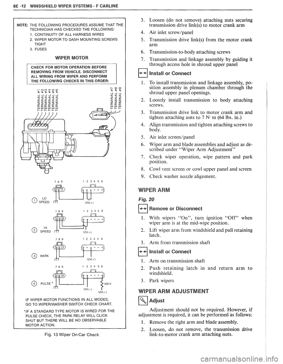
8E -12 WINDSHIELD WIPER SYSTEMS. F CAWLINE
2. WIPER MOTOR TO DASH MOUNTING SCREWS
WIPER MOTOR
REMOVING FROM VEHICLE. DISCONNECT
ALL WIRING FROM WIPER AND PERFORM
GO TO WlPERlWASHER SWITCH CHECK CHART.
E PARK RELAY
WlLL CLICK WlLL BE NO OBSERVABLE
Fig. 13 Wiper On-Gar Check
3. Loosen (do not remove) attaching nuts securing
transmission drive
link(s) to motor crank arm
4. Air inlet screw/panel
5. Transmission drive link(s) from the motor crank
arm
6. Transmission-to-body attaching screws
7. Transmission and linkage assembly by guiding it
through access hole in shroud upper panel
install or Connect
1. To install transmission and linkage assembly, po-
sition assembly in plenum chamber through the
shroud upper panel openings.
2. Loosely install transmission to body attaching
screws.
3. Transmission drive link to motor crank arm and
tighten attaching nuts to
7 N'm (64 lbs. in.)
4. Align transmission and tighten attaching screws to
body.
5. Air inlet screen/panel
6. Wiper arm and blade assemblies and adjust as de-
scribed under "Wiper Arm Adjustment"
7. Check wiper operation, wipe pattern and park
position.
8. Cowl vent screen or cowl upper panel and screen
9. Check washer nozzle alignment.
WIPER ARM
Fig. 20
Remove or Disconnect
1. With wipers "On", turn ignition "Off" when
wiper arm is at the mid-wipe position.
2. Lift wiper arm from windshield and pull retaining
latch.
3. Arm from transmission shaft
Install or Connect
1. Arm on transmission shaft
2. Push retaining latch in and return arm to
windshield.
3. Park wipers
WIPER ARM ADJUSTMENT
Adjust
Adjustment should not be required. However, if
adjustment is required, it can be performed as follows:
1. Remove the right arm and blade assembly.
2. Loosen, do not remove, the transmission drive
link-to-motor crank arm attaching nuts.
Page 1641 of 1825
8E -14 WINDSHIELD WIPER SYSTEMS - F CARLINE
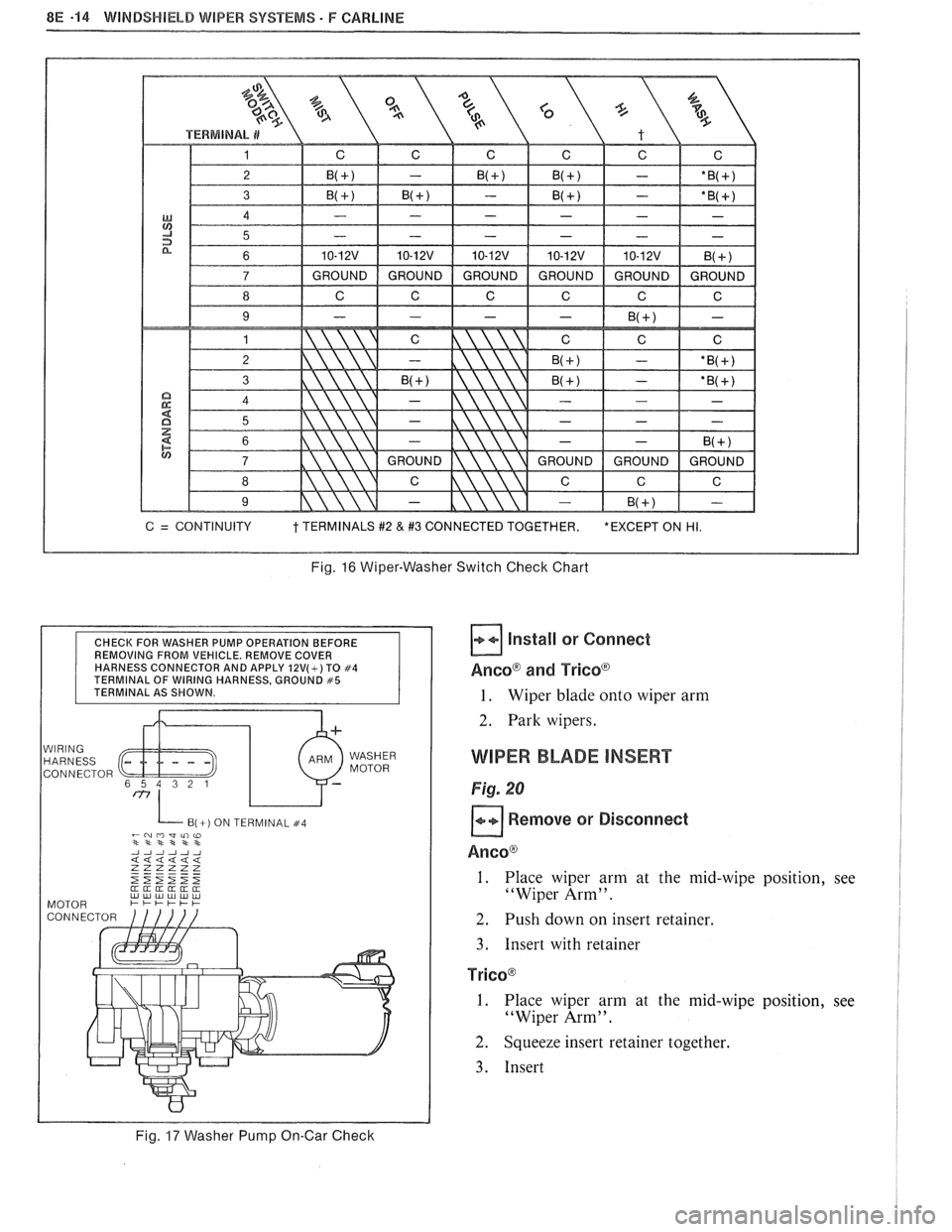
Fig. 16 Wiper-Washer Switch Check Chart
CHECK FOR WASHER PUMP OPERATION BEFORE
REMOVING FROM VEHICLE. REMOVE COVER
HARNESS CONNECTOR AND APPLY
12V(+) TO #4 TERMINAL OF WIRING HARNESS, GROUND #5 TERMINAL AS SHOWN.
WIRING HARNESS
CONNECTOR WASHER
MOTOR
B(+) ON TERMINAL #4 -~mwli)w **st***
Fig. 17 Washer Pump On-Car Check
Install or Connect
AncoB and Tricoa
1. Wiper blade onto wiper arm
2. Park wipers.
WIPER BLADE INSERT
Fig. 20
Remove or Disconnect
Ancoa
1. Place wiper arm at the mid-wipe position, see
"Wiper Arm".
2. Push down on insert retainer.
3. Insert with retainer
TricoB
I. Place wiper arm at the mid-wipe position, see
"Wiper Arm".
2. Squeeze insert retainer together.
3. Insert
Page 1650 of 1825
RADIO SYSTEMS AND ANTENNAS 9A-1
SECTION 9A
0 SYSTEMS AND ANTENNAS
CONTENTS
............................................. General Description .................................... 9A-1 Radio Operation 9A-4
Radio
............................................................ 9A-1 ETR AM/FM Stereo (UM-7) ....................... 9A-4
Antennas
........................................................ 9A- 1 ETR Stereo Cassette (UM-6) ......................... 9A-5
Fixed Antenna
.......................................... 9A- 1 ETR Stereo/Cassette/Eaualizer
Diagnosis ........................................................
Radio ....................... .. ................................
Static and Noise .................................... .....
........................................ Popping Noise
Preliminary Diagnostics
.............................
Antenna ................................. .. ................
Tape Player .................. .... .......................
Service Procedures ....................................
Radio and Speakers ........................... .............
Radio Noise Suppression Equipment ............
Stereo Cassette Tape Player ..........................
Tape & Tape Player Care ........................
(UX-1) ..................................................... 9A-6
Advanced ETR
Stereo/Cassette/Equalizer Touch
Control
.................................... ... .............. 9A-7
On-Car Service .............................................. 9A-9
Radio Receiver
............................................ 9A-9
Radio Steering Wheel Controls
..................... 9A-9
Audio Amplifier
........................................... 9A-9
Radio Suppression
..................................... 9A-9
Front Speaker
................................................. 9A-9
............... Rear Speaker; Sub Woofer Speaker
9A-9
Antenna
..................... .. ............................. 9A- 10
GENERAL DESCRIPUION
RADIO ANTENNAS
For radios and radio use see the "Radio Fixed Antenna
Operation" section. ETR means 'Electronically Tuned The
fixed antenna on the right front fender
Receiver'. cannot be adjusted up or down. It may provide
improved reception in rural areas.
- The fixed antenna is designed to withstand most
car washes without damage. If the antenna becomes
slightly bent, you can straighten it by hand. The
antenna can be replaced if severely bent (by vandalism,
etc.). Antennas must be kept clean for good
performance.
RADIO
Because radio problems are normally repaired at
authorized warranty repair stations, the tendency is to
remove the set when a problem is reported, without any
preliminary diagnosis. This results in a large number
of radios being "No Trouble Found" units when
received by the warranty repair stations. Often the
trouble can be corrected without radio removal. wire.
If equipped with
A/C, the blower motor has a
built-in capacitor. Extra electrical equipment added to
the static if not properly grounded or wiring was
improperly routed.
Weak
FM station reception will be affected by
nearby buildings, car speed and direction. These
"flutter" and "fading" conditions are characteristic of
weak FM signals.
ETR radios require clock and button reset if the
battery is disconnected.
Popping Noise
Static and Noise Operating devices such as turn signals, pushing in
cigarette lighter, operating stop lights, etc., may cause
Ground strap connections must be clean and
a popping noise on distant (weak) AM signals.
tight, spark plug cables must be TVRS type and in
good condition and resistance-type spark plugs used.
Preliminary Diagnostics
Capacitors are used in the generator, heating/air
conditioning system, and fuse panel to reduce noise
The inconvenience of driving without a radio
entering the radio through the feed wires. If the car has
while the set is being serviced can often be avoided if
a heater only, the capacitor is in the blower motor feed
the following quick checks are used to eliminate
Page 1658 of 1825
RADIO SYSTEMS AND ANTENNAS 9A.9
This radio cannot be used on cars without
steering wheel controls. When removed from the
car and reinstalled, the radio will be dead and
LOC will appear on the graphic display. Press
MUTE on the steering wheel to reactivate the
radio.
To Operate the Tape Player:
(NOTE: The following controls are located on
the receiver.)
inserting f ape
Insert cassette into door marked AUTO
REVERSE, so exposed edge of tape enters first.
This turns tape player on and disables the radio.
Tape Bias
When the "CrO" button is lighted, it is set for
chrome or metal tapes; press and the light will go
out (for normal bias tapes).
Reversing Sides
Press program button PROG to play other side
of tape. When end of tape is reached, it
automatically reverses direction and plays the
other side.
NOTE: When lighted arrow located below tape
door points "up," selections listed on the top side of
the tape are being played; when arrow points
"down,"the bottom side is being heard.
Fast Forward
Press FWD button to activate; press PROG to
return to playing speed.
Fast Reverse
Press REV button to activate; press PROG to
return to playing speed.
Music Search
Press SEEK to automatically find the next
selection. Press REPT to repeat the selection
being played.
To Eject Tape
Press EJECT.
NOTE: Power button must be "on." Tape ejects
and radio becomes operative. (It is not nesessary
to eject tapes when leaving car, since internal
pressure is automatically released when ignition
is turned "off.")
For best results,
120 minute tapes are not
recommended.
"Receives
C-QUAMO AM stereo broadcasts.
Most AM stereo stations across the country broadcast
in
C-QUAMO, but some do not. Check with your
local station for compatibility in your area.
C-QUAMO is a Registered Trademark of
Motorola, Inc.
ON-GAR SERVICE
RADIO RECEIVER
Figures 606 and 607
Remove or Disconnect
1. Negative battery cable.
2. Radio/AC-Heater console trimplate.
3. Four (4) radio retaining screws.
4. Pull radio straight out.
5. Power, speaker and antenna connectors. Remove
radio.
6. Transfer attaching parts (clips, brackets, etc.) to
new radio if unit is to be replaced.
Install or Connect
To replace, reverse removal procedure.
RADIO STEERING WHEEL CONTROLS
Refer to Section 3B4 for removal procedure.
AUDIO AMPLIFIER
Figure 610
Remove or Disconnect
5. Two (2) harness connectors.
6. Three (3) attaching screws and remove bracket
from amplifier.
Install or Connect
Reverse removal procedure to reinstall.
RADIO SUPPRESSION EQUIPMENT
When installing a new radio, or when noise is a
problem, insure that radio suppression equipment is
present and properly installed.
FRONnSPEAKER
Figure 606
Remove or Disconnect
1. Instrument panel pad (see Section 8C).
2. Four (4) screws holding speaker in instrument
panel carrier.
3. Lift speaker out of instrument panel. Disconnect
wiring.
Install or Connect
1. Negative battery cable. Reverse removal procedure to install.
2. Right side
instrument close out panel.
3. Two (2) amplifier bracket to instrument panel REAR SPEAKER; SUB-WOOFER SPEAKER
screws.
Rear speakers are mounted in the rear quarter
4. Lower audio amplifier and bracket out of trim panel. See Section
2N in the body portion of this
instrument panel. manual for complete details
of replacement.
Page 1660 of 1825
RADIO SYSTEMS AND ANTENNAS 9A.11
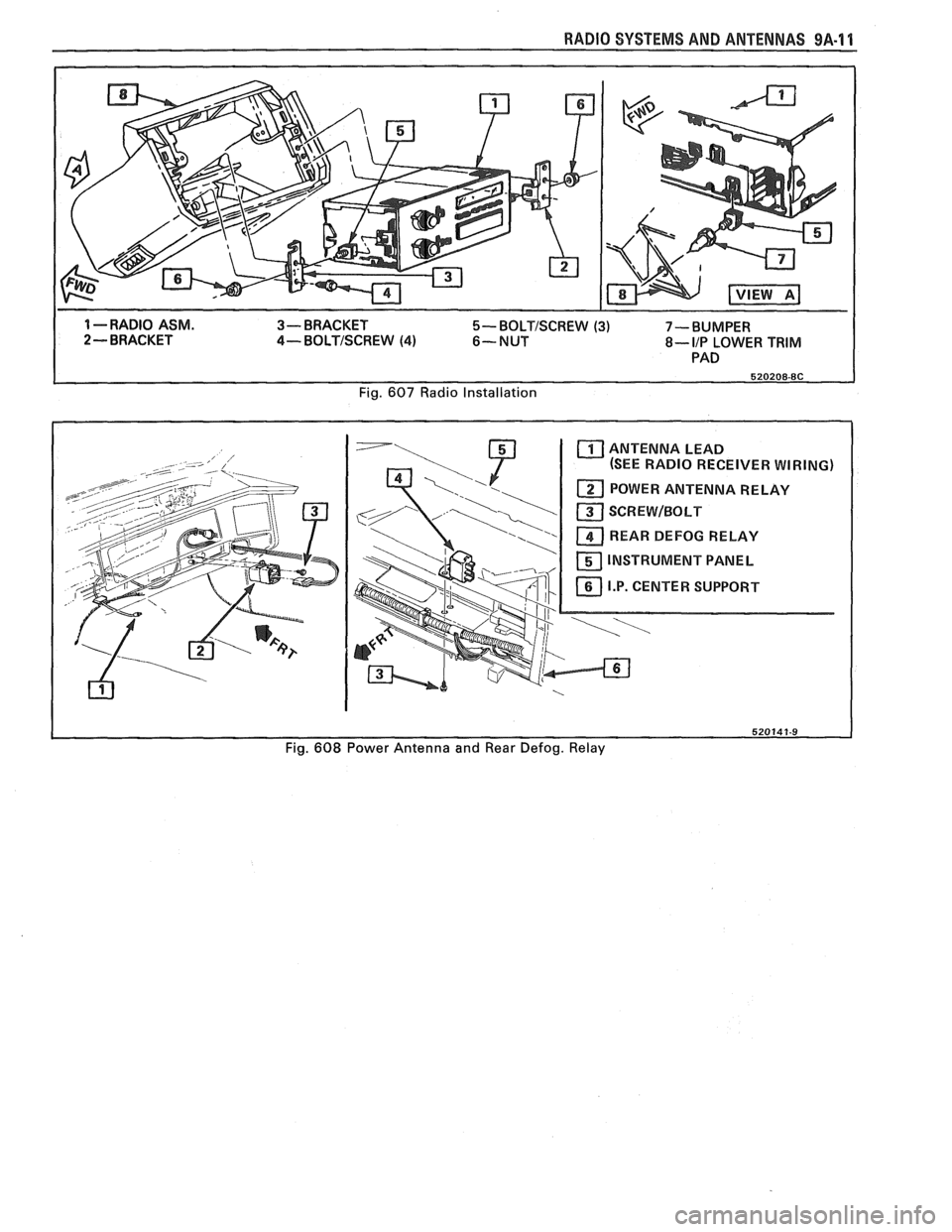
1 --RADIO ASM. 3- BRACKET 5- BOLTISCREW (3) 7-BUMPER
2 - BRACKET 4- BOLTISCREW (4) 6-NUT 8- IIP LOWER TRIM
PAD
Fig.
607 Radio Installation
ANTENNA LEAD
(SEE RADIO RECEIVER WIRING)
REAR DEFOG RELAY
INSTRUMENT PANEL
Fig.
608 Power Antenna and Rear Defog. Relay
Page 1667 of 1825
VACUUM SUPPLY
Tht vacuum to operate the Cruise Control servo
can come from: manifold vacuum connected straight
to the servo, from manifold through a vacuum storage
tank, or straight from a vacuum pump. For specific
vacuum routing, see On-Car Service.
ELECTRICAL AND VACUUM RELEASE
SWITCHES
These switches are used to disengage the cruise
control system. An electrical release switch mounted
on the brake pedal bracket (and clutch pedal bracket
on cars equipped with manual transaxle) disengages
the system electrically when the brake (or clutch) pedal is
depressed. This is done by interrupting the flow of
current to the controller. A vacuum release valve
mounted on the brake pedal bracket vents the trapped
vacuum in the servo to atmosphere when the brake
pedal is depressed, allowing the servo unit to more
quickly return the throttle to idle position. This is done
by routing a separate hose directly to the servo from
the normally closed vacuum switch. These two types
of switches will also sometimes be combined with stop
light switch, TCC switch, or other switches. For
specific usage and adjustment of these switches, see
On-Car Service.
ELECTRICAL HARNESS
For specific wiring and connector locations, see
Section
8A-34, 'Cruise Control'.
Improper operation can be caused by one or a
CRUISE SYSTEM SURGES t combination of mechanical, electrical and vacuum The servo and throttle linkages should operate problems. In resolving any cruise system operating
problem, first make a visual inspection. Check the freely
and smoothly. This linkage should be
system to ensure there are no bare, broken, or adjusted
as described in the On-Car Service
disconnected wires or any pinched, damaged,
-or portion of this section.
disconnected vacuum hoses. The servo and throttle
e Check hose routing for pinches, leaks or
linkage should operate freely and smoothly. The servo restrictions.
(See vacuum schematics in the
linkage should be adjusted as described in the On-Car On-Car
Service portion of this section).
Service portion of this section. See
Section
8A-34, 'Cruise Control'.
CRUISE SET SPEED HIGH OR LOW
Since any problem in this system is either
vacuum, mechanical, or electrical, the technician
should perform a few initial checks before turning to
Section
8A. This can be done by first eliminating a
vacuum or mechanical problem by starting the engine
and using finger to feel for source vacuum at the servo,
and by visual inspection of vacuum release valve,
throttle linkage, vacuum hoses, etc. If preliminary
inspection reveals no solution and the system is
inoperative, use the diagnostic information in Section
8A-34, 'Cruise Control'.
Several versions of a quick check instrument
similar to tool 5-34185 are available. This quick check
instrument is installed in place of the controller and
determines which part of the system has a problem.
Instructions on the operation of the instrument will be
provided with the unit. Check vacuum hoses for
proper routing,
restrictions or leaks. Adjust or replace as
required. (See vacuum schematics in the On-Car
Service portion of this section.)
e Check servo linkage for excess slack and adjust
as described in the On-Car Service portion of this
section.
s If no system problem is noted, replace the
electronic controller (module).
EXCESSIVE CRUISE SPEED LOSS ON HILLS
e Check hoses for vacuum leaks. (See vacuum
schematics in the On-Car Service portion of this
section).
e Determine if check valve is functional (where
applicable).
CRUISE TAP-UP & TAP-DOWN
If all other functions of cruise control are working
except "tap-up" and "tap-down" the controller
(module) is at fault.
Page 1675 of 1825
9G-2 MISCELLANEOUS ACCESSORIES
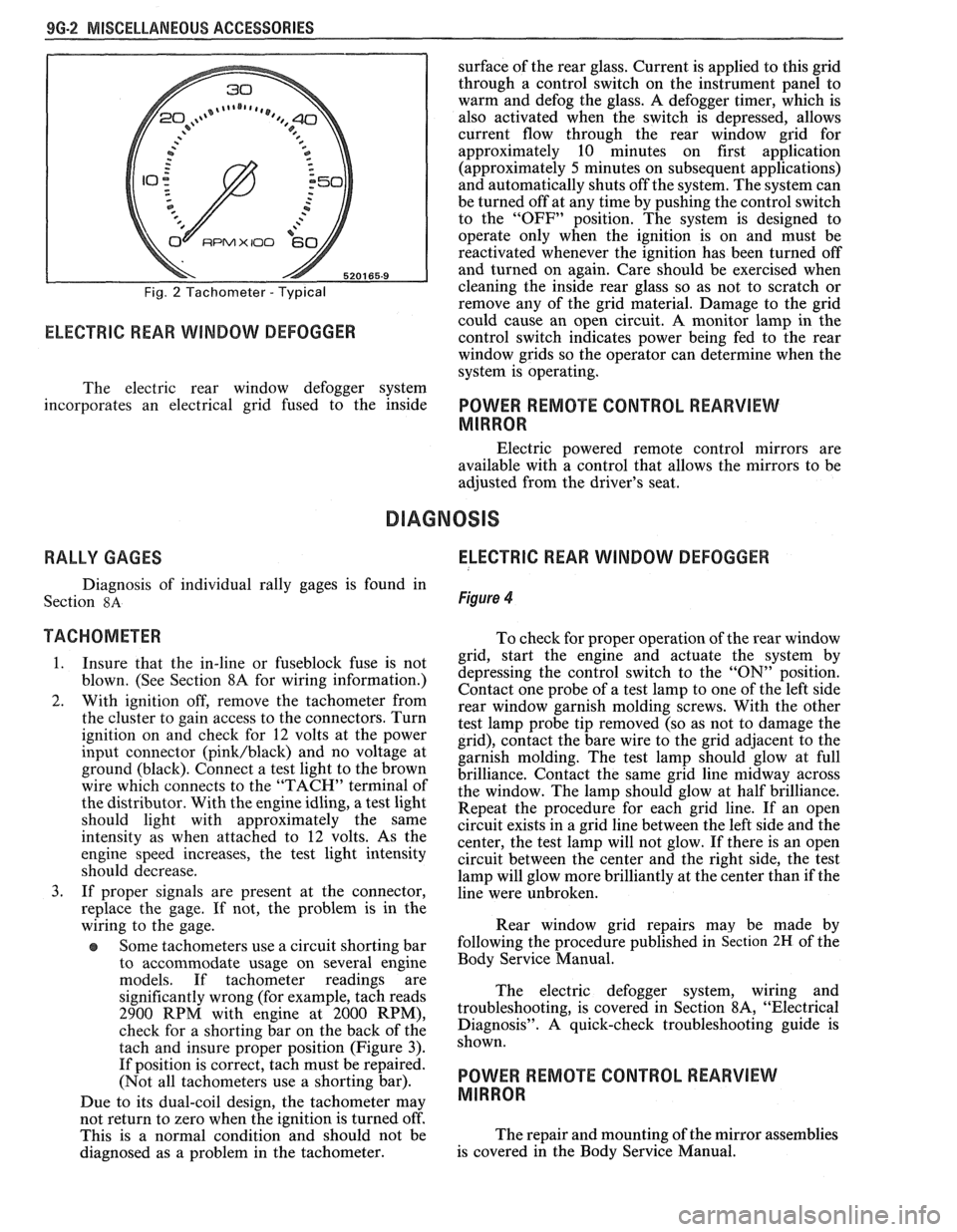
Fig. 2 Tachometer - Typical
RPMX I00 €31-
ELECTRIC REAR WINDOW DEFOGGER
surface of the rear glass. Current is applied to this grid
through a control switch on the instrument panel to
warm and defog the glass. A defogger timer, which is
also activated when the switch is depressed, allows
current flow through the rear window grid
for
approximately 10 minutes on first application
(approximately
5 minutes on subsequent applications)
and automatically shuts off the system. The system can
be turned off at any time by pushing the control switch
to the "OFF" position. The system is designed to
operate only when the ignition is on and must be
reactivated whenever the ignition has been turned off
and turned on again. Care should be exercised when
cleaning the inside rear glass so as not to scratch or
remove any of the grid material. Damage to the grid
could cause an open circuit. A monitor lamp in-the
control switch indicates power being fed to the rear
window grids so the operator can determine when the
system is operating.
The electric rear window defogger system
incorporates an electrical grid fused to the inside
POWER REMOTE CONTROL REARVIEW
MIRROR
Electric powered remote control mirrors are
available with a control that allows the mirrors to be
adjusted from the driver's seat.
RALLY GAGES ELECTRIC REAR WINDOW DEFOGGER
Diagnosis of individual rally gages is found in
Section
8A Figure 4
TACHOMETER To check for moper o~eration of the rear window
1. Insure that the in-line or fuseblock fuse is not
blown. (See Section 8A for wiring information.)
2. With ignition off, remove the tachometer from
the cluster to gain access to the connectors. Turn
ignition on and check for
12 volts at the power
input connector
(pink/black) and no voltage at
ground (black). Connect a test light to the brown
wire which connects to the "TACH" terminal of
the distributor. With the engine idling, a test light
should light with approximately the same
intensity as when attached to
12 volts. As the
engine speed increases, the test light intensity
should decrease.
3. If proper signals are present at the connector,
replace the gage. If not, the problem is in the
wiring to the gage.
Some tachometers use a circuit shorting bar
to accommodate usage on several engine
models. If tachometer readings are
significantly wrong (for example, tach reads
2900 RPM with engine at 2000 RPM),
check for a shorting bar on the back of the
tach and insure proper position (Figure
3).
If position is correct, tach must be repaired.
(Not all tachometers use a shorting bar).
Due to its dual-coil design, the tachometer
may
- grid, start the engine a& actuate the system by
depressing the control switch to the
"ON" position.
Contact one probe of a test lamp to one of the left side
rear window garnish molding screws. With the other
test lamp probe tip removed (so as not to damage the
grid), contact the bare wire to the grid adjacent to the
garnish molding. The test lamp should glow at full
brilliance. Contact the same grid line midway across
the window. The lamp should glow at half brilliance.
Repeat the procedure for each grid line. If an open
circuit exists in a grid line between the left side and the
center, the test lamp will not glow. If there is an open
circuit between the center and the right side, the test
lamp will glow more brilliantly at the center than if the
line were unbroken.
Rear window grid repairs may be made by
following the procedure published in
Section 2H of the
Body Service Manual.
The electric defogger system, wiring and
troubleshooting, is covered in Section
8A, "Electrical
Diagnosis". A quick-check troubleshooting guide is
shown.
POWER REMOTE CONTROL REARVIEW
MIRROR
not return to zero when tvhe ignition is turned off'.
This is a normal condition and should not be The
repair and mounting of the mirror assemblies
diagnosed as a problem in the tachometer. is
covered in the Body Service Manual.