1988 PONTIAC FIERO ground clearance
[x] Cancel search: ground clearancePage 114 of 1825
CHASSIS SHEET METAL 2@-7
3. During the above flash time period (1 to 10 min-
utes), apply appropriate "conventional" interior acrylic lacquer color as required and allow
painted part to dry for
4 to 5 hours before install-
ing on car.
RlGlD OW HARD ABS PMS"TIC PARTS
Rigid or hard ABS plastic requires no primer.
"Conventional" interior acrylic lacquers adhere satis-
factorily to hard ABS plastics.
Procedure
1. Wash part thoroughly with a cleaning solvent
(Acrylic-Clean, Pre-Kleano, Prep-Sol or equiv-
alent) to remove any dirt or grease.
2. Apply appropriate "conventional" interior
acrylic lacquer color. Apply only sufficient
color for proper hiding to avoid washout of
"grain" effect.
3. Allow to dry and then install part.
VINYL AND FLEXIBLE (Son) ABS
PLASTIC PARTS
The outer cover or skin material of "flexible"
instrument panel cover (pad) assemblies is made of an
ABSIPVC plastic blend. The same is true of many
"padded" door trim assemblies. The soft cushion pad-
ding under the I.P. skin is urethane foam plastic. The
most widely used
"flexible" vinyls (poly vinyl chlo-
ride)
are coated fabrics, such as used in seat trim,
some door trim assemblies, molded headlining panels
and sun visors. Most head rests are "flexible" vinyls.
Examples of "hard vinyls are: door and front seat
back assist handles and coat hooks.
The paint system of vinyl and flexible ABS
plastic involves the use of interior "vinyl" color and a
clear vinyl top coat.
Procedure
1. Wash part thoroughly with a vinyl cleaning and
preparation solvent ("Vinyl Press"
- Ditzler,
"Vinyl Prep Conditioner"
- Detroit Autobody
or equivalent) to remove greasy film or silicone.
Wipe off cleaner while still wet with clean,
lint-
free cloth.
2. Immediately after wiping face dry, apply inte-
rior "vinyl" color in wet coats allowing suffi-
cient flash time between coats (see label
directions on can). Use proper "vinyl" color as
designated by interior trim combinations. Apply
only sufficient color for proper hiding to avoid
washout of "grain" effect. No primer or
primer-
sealer is required.
3. Before the final vinyl color coat has dried, apply
two coats of clear vinyl top coat spray (instru-
ment panels will require the "nonglare" clear top
coat). Do not allow the first spray coat to com-
pletely dry before spraying on the second. Use
top coat with appropriate gloss level to match adjacent similar components. This
clear coat is
necessary to control the gloss requirement and
prevent
'tracking" (rubbing-off) of the color
coat after drying.
4. Allow to dry according to label directions before
installing part.
ON-VEHICLE SERVICE
CONCEALED HEADLIGHTS
The concealed headlights used on this model are
electrically operated. When the headlights are turned
on, solid state circuitry activates the actuators. This
same circuitry senses when the actuators stop moving
and removes the ground to deactivate the actuators.
When the headlights are turned off, the actuators run
in opposite direction closing the headlight doors.
Should an electrical failure occur in the head-
light circuit, they may be raised manually by rotating
the knob on the actuator in a counterclockwise direc-
tion until the headlights are fully open. The headlights
may be lowered by rotating the knob on the actuator in
a clockwise direction until the headlights are fully
closed.
For electrical circuit information and diagnosis,
refer to Section
8A of this manual.
If it is desired to raise the headlights with the
lights off, either of the following procedures may be
used:
1. Turn the lights on. After the headlights are
open, disconnect the electrical connections at
the actuator connectors. Turn the lights off. The
headlights will now remain in the open position.
2. Turn the parking lights on. Depress the head-
light rocker switch lightly. The headlights may
then be raised "up" fully with the lights off.
Adjust
Because of the number of adjustments possible
and the number of attaching points of the concealed
headlight body assembly
(9), only those attachments
which control the adjustment desired should be loos-
ened. Make one
adjbstment at a time.
NOTICE: The headlight door does NOT have
slotted mounting holes and therefore is not
adjustable by itself. This insures proper clearance
between the headlight door and the hood and
fenders in both the raised and lowered positions.
The entire headlight body assembly must be
adjusted to achieve the desired appearance and
fit. Care should be exercised when adjusting the
headlight body assembly. Severe hammer blows could damage the die cast aluminum headlight
body assembly.
TO RAISE OR LOWER the headlight body
assembly, proceed as follows:
1. Open hood.
2. Raise headlights.
Page 128 of 1825
STEERING, SUSPENSION, VIBES AND WHEELS DIAGNOSIS 3-3
Steering Wheel Kick-Back (Power)
Inspect
e Air in system
e Loose steering gear mounting
e Joints from column to steering gear loose or worn
e Tie rod ends loose
Worn or missing check valve
(800 series)
e Wheel bearings worn
e See "Too Much Play In Steering" for other
possible causes.
Steering Wheel Surges Or Jerks (Power)
Inspect
Hydraulic system - Make pressure test with gage
J 5176-D or
J 25323
e Sluggish steering gear valve
Loose pump drive belt
Cupped Tires
Inspect
Front-wheel or rear-wheel alignment
e Strut dampeners or shock absorbers weak
e Wheel bearing worn
e Excessive tire or wheel runout
e Worn ball joint
a Loose steering gear adjustment
POWER RECIRCULATING BALL
SEERING GEAR DIAGNOSIS
Hissing Noise
There is some noise in all power steering systems.
One of the most common is a hissing sound when the
steering wheel is turned and the car is not moving. This
noise will be most evident when turning the wheel
while the brakes are applied. There is no relationship
between this noise and steering performance. Do not
replace the valve unless the "hissing" noise is extremely
objectionable. A replacement valve will also have a
slight noise, and is not always a cure for the condition.
Check that the intermediate shaft joints are not loose.
Rattle or Chucking Noise
Inspect -
Pressure hose grounding out
e Tie rod ends loose
e Steering gear attachment loose
a Loose pitman shaft "over-center" adjustment.
A slight rattle may occur on turns because of
increased clearance off the "high point". This is
normal and clearance must not be reduced below
specified limits to eliminate this slight rattle.
Poor Return of Steering Wheel to Center
Front-wheel alignment
Wheel bearing worn
Tie rod end binding
Ball joint binding
Steering wheel rubbing against turn signal
housing
Steering gear adjustments
Tight or frozen intermediate steering shaft
Sticky or plugged spool valve
Momentary Increase in Effort Whsn Turning
Wheel Fast to Right or Left
Inspect
High internal leakage
Steering Wheel Surges or Jerks When Turning
With
Engine Running Especially During Parking
ln8pe~t
e Insufficient pump pressure
Sticky flow control valve
Excessive Wheel Kickback or Loose Steering
Air in system
Steering gear attachment loose
Tie rod ends loose
Wheel bearings worn
Steering gear flexible coupling loose on shaft or
rubber disc mounting nuts loose
Loose thrust bearing preload adjustment
Excessive "over-center" lash
Worn pressure port check valve
Hard Steering or Lack of Assist
(Especially During Parking)
-
Brakes applied while turning steering wheel
Intermediate shaft damaged or worn
e Sticky flow control valve
Insufficient pump pressure
Excessive internal pump leakage
Excessive internal steering gear leakage
STEERING LINKAGE DIAGNOSIS
Excessive Play or Looseness in Steering Systern
inspect
r, Worn upper ball joints
e Steering gear worm bearings loosely adjusted
Page 232 of 1825
TIRES AND WHEELS 3E-1
RES AND WHEELS
NOTICE: All wheel bolt and nut fasteners are important attaching parts in that they could affect the
performance of vital components and systems, and/or could result in major repair expense. They must be replaced
with one of the same part number or with an equivalent part if replacement becomes necessary. Do not use a
replacement part of lesser quality or substitute design. Torque values must be used as specified during reassembly
to assure proper retention of parts.
CONTENTS
Diagnosis ............................................... Section 3 Tire Repair ................................................... 3E-5
General Information .......................... ..... 3E-1 Waddle ........................................................ 3E-5
........ Replacement Tires ....................... ... 3E- 1 Measuring Wheel Runout ............................ 3E-6
P-Metric Tires ...................... .. ................... 3E-2 Spare Tire ...................................................... 3E-6 ................................................ Tire Placard 3E-2 Match Mounting ......................................... 3E-7
.......................................................... Wheels 3E-2 Balancing Tire and Wheel ............................ 3E-7
....................... Maintenance and Adjustments .............. 3E-2 General Balance Precautions 3E-7 ...................................... Wheel Repair .............................................. 3E-2 Off-Car Balancing 3E-8 .............................. Metric Wheel Nuts and Studs .................... .. 3E-3 On-Car Balancing .. ...... 3E-8
......................................... Inflation of Tires ........................................ 3E-3 Wheel Weights 3E-8 .................... Tire Rotation ........................... ...... . 3E-3 Correcting Non-Uniform Tires 3E-8 .......................... Tire Chain Usage ........................................ 3E-4 Aluminum Wheel Cleaning 3E-9 Aluminum Wheel Hub Cap ......................... 3E-9 Service Operations ..................................... 3E-4 Aluminum Wheel Porosity Repair .............. 3E-9 ......................... Wheel Removal .... .......... 3E-4 Aluminum Wheel Refinishing ...................... 3E-9 Tire Mounting and Dismounting ................. 3E-5 Wheel Nut Torque 3E-10 ......................................
GENERAL INFORMATION ~t is recommended that new tires be installed in
pairs on the same axle. If it is necessary to replace only
The tires and are one tire, it should be paired with the tire having the
designed to operate satisfactorily with loads up to and
most tread, to equalize braking traction. including the full rated load capacity when inflated to
Although they may appear different in tread
the recommended inflation pressures.
design, tires built by different manufacturers with
Correct tire pressures, wheel alignment and identical TPC specification numbers, can be
driving techniques have an important influence on tire
intermixed on the same car. life. Heavy cornering, excessive rapid acceleration, and
heavy braking will increase tire wear.
REPLACEMENT TIRES
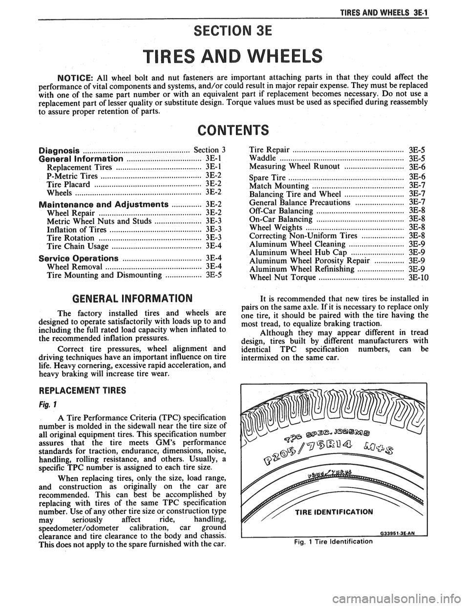
Fig. 1
A Tire Performance Criteria (TPC) specification
number is molded in the sidewall near the tire size of
all original equipment tires. This specification number
assures that the tire meets
GM's performance
standards for traction, endurance, dimensions, noise,
handling, rolling resistance, and others. Usually, a
specific TPC number is assigned to each tire size.
When replacing tires, only the size, load range,
and construction as originally on the car are
recommended. This can best be accomplished by
replacing with tires of the same TPC specification
number. Use of any other tire size or construction type
may seriously affect ride, handling,
speedometer/odometer calibration, car ground
clearance and tire clearance to the body and chassis.
This does not apply to the spare furnished with the car.
v// TIRE IDENTIFICATION
Fig. 1 Tire Identification
Page 233 of 1825
3E.2 TIRES AND WHEELS
P-METRIC SIZED TIRES
Figs. 1 through 4
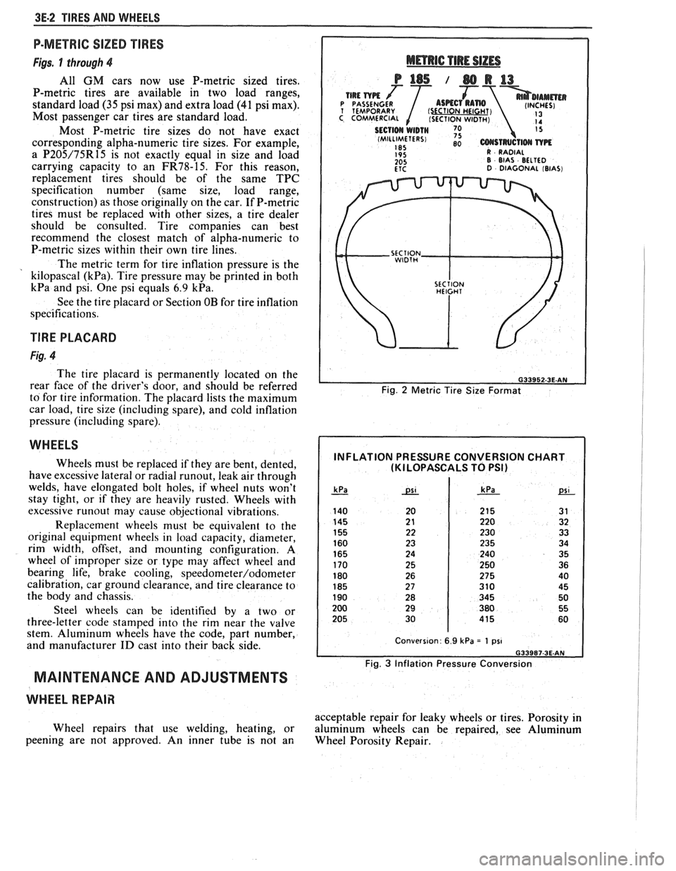
All GM cars now use P-metric sized tires.
P-metric tires are available in two load ranges,
standard load
(35 psi max) and extra load (41 psi max).
Most passenger car tires are standard load.
Most P-metric tire sizes do not have exact
corresponding alpha-numeric tire sizes. For example,
a
P205/75R15 is not exactly equal in size and load
carrying capacity to an
FR78-15. For this reason,
replacement tires should be of the same TPC
specification number (same size, load range,
construction) as those originally on the car. If P-metric
tires must be replaced with other sizes, a tire dealer
should be consulted. Tire companies can best
recommend the closest match of alpha-numeric to
P-metric sizes within their own tire lines.
The metric term for tire inflation pressure is the
kilopascal
(kPa). Tire pressure may be printed in both
kPa and psi. One psi equals 6.9 kPa.
See the tire placard or Section OB for tire inflation
specifications.
TlRE PLACARD
Fig. 4
The tire placard is permanently located on the
rear
face of the driver's door, and should be referred
to for tire information. The placard lists the maximum
car load, tire size (including spare), and cold inflation
pressure (including spare).
WHEELS
Wheels must be replaced if they are bent, dented,
have excessive lateral or radial
runout, leak air through
welds, have elongated bolt holes, if wheel nuts won't
stay tight, or if they are heavily rusted. Wheels with
excessive
runout may cause objectional vibrations.
Replacement wheels must be equivalent to the
original equipment wheels in load capacity, diameter,
rim width, offset, and mounting configuration.
A
wheel of improper size or type may affect wheel and
bearing life, brake cooling,
speedometer/odometer
calibration, car ground clearance, and tire clearance to
the body and chassis.
Steel wheels can be identified by a two or
three-letter code stamped into the rim near the valve
stem. Aluminum wheels have the code, part number,
and manufacturer
ID cast into their back side.
MAINTENANCE AND ADJUSTMENTS
WHEEL REPAIR
Wheel repairs that use welding, heating, or
peening are not approved. An inner tube is not an
Fig. 2 Metric Tire Size Format
INFLATION PRESSURE CONVERSION CHART (KI LOPASCALS TO PSI)
Fig. 3 Inflation Pressure Conversion
acceptable repair for leaky wheels or tires. Porosity in
aluminum wheels can be repaired, see Aluminum
Wheel Porosity Repair.
Page 347 of 1825
6-2 ENGINE GENERAL INFORMATION
6E3 - Fuel Injection (Ported) This section has information
on all exhaust
system parts, such as tailpipes, mufflers, and the
SECTION 6F - EXHAUST SYSTEM catalytic converter.
GENERAL INFORMAflION
CLEANLINESS AND CARE
An automobile engine is a combination of many
machined, honed, polished and lapped surfaces with
tolerances that are measured in the ten-thousandths of
an inch. When any internal engine parts are serviced,
care and cleanliness are important. A liberal coating of
engine oil should be applied to friction areas during
assembly, to protect and lubricate the surfaces on
initial operation. Throughout this section, it should be
understood that proper cleaning and protection of
machined surfaces and friction areas is part of the
repair procedure. This is considered standard shop
practice, even if not specifically stated. PREVENTING
DAMAGE AND IN
CONTRIBUTING TO RELIABLE ENGINE
PERFORMANCE.
When raising or supporting the engine for any
reason, do not use a jack under the oil pan. Due to the
small clearance between the oil pan and the oil pump
screen, jacking against the oil pan may cause it to be
bent against the pump screen resulting in a damaged
oil pick-up unit.
When working on the engine, remember that the
12-volt electrical system is capable of causing short
circuits. When performing any work where electrical terminals could possibly be grounded, the ground cable
of the battery should be disconnected at the battery.
Any time the carburetor or air cleaner is
train components are removed removed, the intake opening should be covered. This for service, they should be in order' will protect against entrance of foreign be installed in the same locations, and with the same material, which could follow the intake passage into mating surfaces, as when removed
the cylinder and cause extensive damage when the -
Battery cables should be disconnected before any engin; is started.
major work is performed on the engine. Failure to IN THE MECHANICAL PROCEDURES
disconnect cables may result in damage to wire harness DESCRIBED IN THIS SECTION, GENERALLY
or other electrical parts. NO
REFERENCES WILL BE MADE TO THE
REMOVAL OF OPTIONAL EQUIPMENT SUCH
ENGINE SERVICE AS POWER STEERING PUMP, AIR
CONDITIONING COMPRESSOR, ETC.
THE FOLLOWING INFORMATION ON SHOULD IT BECOME NECESSARY TO
ENGINE SERVICE SHOULD BE NOTED REMOVE ANY SUCH ITEM TO
PERFORM
CAREFULLY, AS IT IS IMPORTANT IN OTHER SERVICE, REFER TO THE
APPROPRIATE SECTION OF THIS SERVICE
MANUAL FOR SPECIFIC INFORMATION.
ENGINE PERFORMANCE DIAGNOSIS
INTRODUCTION interchangeably for so long, it was necessary to decide
on the most common usage and then define them. If the
Engine Performance procedures are definition is not understood, and the exact Symptom is
guides that will lead to the most probable causes of not used, the Diagnostic procedure will not work. engine performance complaints. They cover the
components of the fuel, ignition, and mechanical It
is important to keep two facts in mind:
systems that could cause a particular
complaint, and 1. The procedures are written to diagnose problems
then outline repairs in a logical sequence. on cars
that have
"run well at one time" and
that time and wear have created the condition.
It is important to determine if the
"Service ~~~i~~ soon- light is "ON,~' or has come for 2. All possible causes cannot be covered,
a short interval while driving. If the
"Service Engine particularly with regard to emission controls. If
Soon" light has come "ON," the Computer doing the work prescribed does not correct the
Command Control System or DECS should be complaint, then either the wrong Symptom was
checked for stored
"Trouble Codes" (See Diagnostic used, or a more detailed analysis will have to be
Circuit Check, Section 6E, for the engine you are made.
working on) which may indicate the cause for the All of the Symptoms can be caused by worn out
performance
complaint.Each Symptom is defined, and or defective parts such as Spark Plugs, Ignition
it is important that the correct one be selected, based Wiring, etc. If time and/or mileage indicate that
on the complaints reported or found. The definition of parts should be replaced, it is recommended that
each symptom is included with the symptom. it
be done.
The words used may not be what you are used to Refer to:
in all cases, but because these terms have been used
@ Section 6E - Driveability and Emissions
Page 348 of 1825
ENGINE GENERAL INFORMATION 6-3
B, Section 6E2 - Fuel Injection (TBI)
B, Section 6E3 - Fuel Injection (Ported)
ENGINE MECHANICAL DIAGNOSIS
The following diagnostic information covers common problems and possible causes. When
the proper diagnosis is made, the problem should be corrected by adjustment, repair or part
replacement as required. Refer to the appropriate section of the manual for these procedures.
EXCESSIVE OIL LOSS
B, External oil leaks. Tighten bolts and/or replace o Continuous high speed driving, and/or severe
gaskets and seals as necessary. usage
such as trailer hauling, will normally cause
decreased oil mileage.
e Improper reading of dipstick. Check oil with car PCV system malfunctioning. on a level surface and allow adequate drain-down Valve guides and/or valve stem seals worn, or time.
seals omitted. Ream guides and install oversize
service valves and/or new valve stem seals.
Improper Use S.A'E' Piston rings broken, worn, or not seateded. Allow viscosity for prevailing temperatures. See
adequate time for rings to seat. Replace broken
Owner's Manual for proper specifications.
or worn rings, as necessary.
Piston improperly installed or misfitted.
LOW OIL PRESSURE
Slow idle speed. Set idle speed to correct
specification, if not ECM controlled.
Incorrect, or malfunctioning, oil pressure switch.
Incorrect, or malfunctioning, oil pressure gage.
Replace with proper gage.
.*
Improper oil viscosity, or diluted oil. install oil of
proper viscosity for expected temperature, or
install new oil if diluted with moisture or
unburned fuel mixtures.
o Oil pump worn or dirty.
e Plugged oil filter.
e Oil pickup screen loose or plugged.
B, Hole in oil pickup tube.
e Excessive bearing clearance. Replace if necessary.
o Cracked, porous or plugged oil galleys. Repair or
replace block.
o Galley plugs missing or misinstalled. Install
plugs, or repair as necessary.
VALVE TRAIN NOISE
e Low oil pressure. Repair as necessary. (See o Broken valve spring.
preceding diagnosis for low oil pressure.)
o Sticking valves.
o Loose rocker arm attachments. Inspect and B, Lifters worn, dirty, or defective. Clean, inspect,
test and replace as necessary.
repair as necessary.
o Camshaft worn, or poor machining. Replace
o Worn rocker arm and/or pushrod. camshaft.
B, Worn valve guides.
ENGINE KNOCK DIAGNOSIS
KNOCKS COLD AND CONTINUES FOR TWO TO THREE MINUTES
INCREASES
WITH TORQUE
o Vacuum operated EFE engines may have valve o Excessive piston to bore clearance. Replace
knock. Replace EFE valve. piston.
e Flywheel contacting splash shield. Reposition
splash shield.
e Loose or broken balancer or drive pulleys.
Tighten, or replace as necessary. Cold engine piston knock usually
disappears when the cylinder is grounded
out. Cold engine piston knock which
disappears in 1.5 minutes should be
considered acceptable.
Page 349 of 1825
6-4 ENGINE GENERAL INFORMATION
Bent connecting rod.
HEAVY KNOCK H0"FVVI"F TORQUE APPLIED
Broken balancer, or pulley hub. Replace parts as e Exhaust system grounded. Reposition as
necessary. necessary.
Loose torque converter bolts. Flywheel
cracked.
e Excessive main bearing clearance. Replace as
Accessory belts too tight or nicked. Replace
necessary.
and/or tension to specs as necessary.
e Excessive rod bearing clearance. Replace as
necessary.
LIGHT KNOCK HOT
Detonation or spark knock. Check operation of e Loose torque converter bolts.
EST or ESC (See Section
6D or 6E). Check e Exhaust leak at manifold. Tighten bolts and/or
engine timing and fuel quality.
replace gasket.
8 Excessive rod bearing clearance. Replace
bearings as necessary.
KNOCKS ON INITIAL START-UP BUT ONLY LASTS A FEW SECONDS
Noisy mechanical fuel pump. Replace pump.
When the engine is stopped, some valves
will be open. Spring pressure against lifters
Improper oil viscosity. Install proper oil viscosity will
tend to bleed lifter down. Attempts to
for expected temperatures. See Owner's Manual. repair
should be made only if the problem
is consistent.
Hydraulic lifter bleed down. Clean, test and @ Excessive crankshaft end clearance. Replace
replace as necessary. crankshaft
thrust bearing.
@ Excessive front main bearing clearance. Replace
worn parts.
KNOCKS AT IDLE HOT
Loose or worn drive belts. Tension and/or @ Excessive piston pin clearance. Ream and install
replace as necessary. oversize pins. (VIN R and 2) or replace piston
A/C Compressor or generator bearing. Replace and
pin.
as necessary.
e Connecting rod alignment. Check and replace
rods as necessary.
Noisy mechanical fuel pump. Replace pump.
8 Insufficient piston to bore clearance. Hone bore
Valve train. Replace parts as necessary. and
fit new piston.
@ Loose crankshaft balancer. Torque and/or
Improper oil viscosity. Install proper viscosity oil
replace worn parts.
for expected temperature4 See Owner" e Piston pin offset to wrong side. Install correct
ENGINE OVERHEATS
Coolant system leak, oil cooler system leak, or
2. Belt slipping or damaged. Replace tensioner, or
coolant recovery system not operating. Check for belt, as required.
leaks and correct as required. Check coolant
3. Thermostat stuck closed. Check and replace if
recovery tank, hose and radiator cap.
required.
4. Electrical cooling fan operation. See the
ELECTRICAL TROUBLESHOOTING
MANUAL.
5. Head gasket leaking. Check and repair as
required.
Page 370 of 1825
2.8 LITER V-6 6A2-19
4. Measure the crankpin for out-of-round or taper
with a micrometer. If not within specifications,
replace or recondition the crankshaft. If within
specifications and a new bearing is to be installed,
measure the maximum diameter of the crankpin,
to determine new bearing size required.
5. If within specifications, measure new or used
bearing clearance with Plastigage or its
equivalent.
NOTICE: If a bearing is being fitted to an
out-of-round crankpin, be sure to fit to the
maximum diameter of the crankpin. If the bearing
is fitted to the minimum diameter and the
crankpin is out-of-round .025mm interference
between the bearing and
crankpin will result in a
rapid bearing failure.
a.
Place a piece of gaging plastic the full width
of the
crankpin as contacted by the bearing
(parallel to the crankshaft).
b. Install
the bearing in the connecting rod and
cap.
c. Install
the rod cap and evenly torque nuts
to specifications. Do not turn the crankshaft
with gaging plastic installed.
d. Remove
the rod cap and using the scale on
the gaging plastic envelope, measure the
gaging plastic width at the widest point.
6. If
the clearance exceeds specifications, select a
new, correct size, bearing and remeasure the
clearance.
If clearance cannot be brought to within
specifications, the
crankpin will have to be
ground undersize. If the
crankpin is already
at maximum undersize, replace crankshaft.
7. Coat the
bearing surface with oil, install the rod
cap and torque nuts to 50
N-m (37 lb. ft.).
8. When all connecting rod bearings have been
installed tap each rod lightly (parallel to the
crankpin) to make sure they have clearance.
9. Measure all connecting rod side clearances (see
specifications) between the rod cap and
crankshaft throw (Figure 6A2-23).
MAIN BEARINGS (FIGURE 6A2-24)
Main bearings are of the precision insert type and
do not utilize shims for adjustment. If clearances are
found to be excessive, a new bearing, both upper and
lower halves, will be required. Service bearings are
available in standard size and undersize.
Selective fitting of both rod and main bearing
inserts is necessary in production in order to obtain
close tolerances. For this reason you may find one half
of a standard insert with one half of a
.016mm
undersize insert which will decrease the clearance
.008mm from using a full standard bearing.
Inspection
In general, the lower half of the bearing (except
# 1 bearing) shows a greater wear and the most distress
from fatigue. If upon inspection, the lower half is
suitable for use, it can be assumed that the upper half
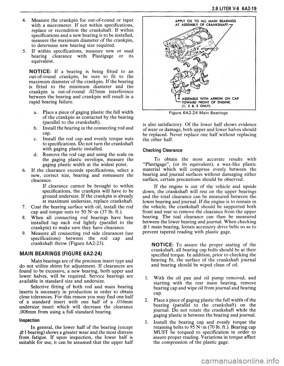
APPLY OIL TO ALL MAlN BEARINGS
E WITH ARROW ON CAP
FRONT OF ENGINE.
(1, 2 8, 3 ONLY).
Figure 6A2-24 Main Bearings
is also satisfactory. Of the lower half shows evidence
of wear or damage, both upper and lower halves should
be replaced. Never replace one half without replacing
the other half.
Checking Clearance
To obtain the most accurate results with
"Plastigage", (or its equivalent), a wax-like plastic
material which will compress evenly between the
bearing and journal surfaces without damaging either
surface, certain precautions should be observed.
If the engine is out of the vehicle and upside
down, the crankshaft will rest on the upper bearings
and the total clearance can be measured between the
lower bearing and journal. If the engine is to remain in
the vehicle, the crankshaft should be supported both
front and rear to remove the clearance from the upper
bearing. The toal clearance can then be measured
between the lower bearing and journal. When checking
# 1 main bearing, loosen accessory drive belts so as to
prevent tapered reading with plastic gage.
NOTICE: To assure the proper seating of the
crankshaft, all bearing cap bolts should be at their
specified torque. In addition, prior to checking the
bearing fit, the surface of the crankshaft journal
and bearing should be wiped clean of oil.
1. With the oil pan and oil pump removed, and
starting with the rear main bearing, remove
bearing cap and wipe oil from journal and bearing
cap.
2. Place a piece of gaging plastic the full width of the
bearing (parallel to the crankshaft) on the
journal. Do not rotate the crankshaft while the
gaging plastic is between the bearing and journal.
3. Install
the bearing cap and evenly torque the
retaining bolts to 95
N.m (70 lb. ft.). Bearing cap
MUST be torqued to specification in order to
assure proper reading. Variations in torque affect
the compression of the plastic gage.