1988 PONTIAC FIERO maintenance schedule
[x] Cancel search: maintenance schedulePage 8 of 1825
GENERAL INFORMATION OA-5
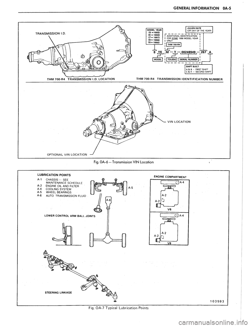
- THM 700-R4 TRANSMISSION I.D. LOCATION
1-1 IOU DAY OF THE YEAR1
I SHIFT BUILT 1 1 A & B = FIRST SHIFT 1 C 5 H - SECOND SHIFT
THM 700-R4 TRANSMISSION IDENTIFICATION NUMBER
VIN LOCATION
I OPTIONAL VIN LOCATION --I I
Fig. OA-6 --Transmission VIN Location
LUBRICATION POINTS
CHASSIS - SEE
MAINTENANCE SCHEDULE
ENGINE OIL AND FILTER
COOLING SYSTEM WHEEL BEARINGS
AUTO TRANSMISSION FLUID
LOWER CONTROL ARM BALL JOINTS
I I
ENGINE COMPARTMENT
STEERING LINKAGE
Fig. OA-7 Typical Lubrication Points
Page 18 of 1825
MAINTENANCE AND LUBRICATION OB-1
SECTION OB
NTENANCE AND LUBR
CONTENTS
Maintenance Schedule, Gasoline .............................................. OB-l
Maintenance Schedules I and 11 .............................................. OB-2
Owner Inspections
......................................................... OB-3
Recommended Fluids and Lubricants ......................................... OB-6
PASSENGER CAR MAINTENANCE SCHEDULE
VEHICLES
WITH GASOLINE ENGINE
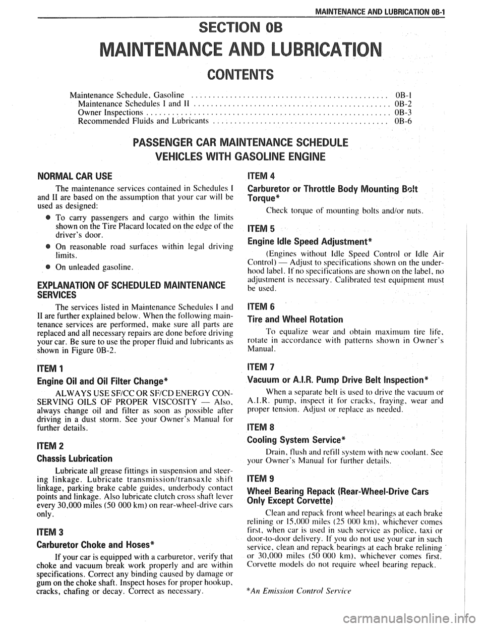
NORMAL CAR USE ITEM 4
The maintenance services contained in Schedules I Carburetor or Throttle Body Mounting Bolt
and 11 are based on the assumption that your car will be Torque* used as designed:
Check torque of mounting bolts and/or nuts. @ To carry passengers and cargo within the limits
shown on the Tire Placard located on the edge of the ITEM 5 driver's door.
@ On reasonable road surfaces within legal driving Engine Idle Speed Adjustment*
limits. (Engines
without Idle Speed Control or Idle Air
Control) - Adjust to specifications shown on the under- @ On unleaded gasoline.
hood label. If no specifications are shown on the label, no
adjustment is necessary. Calibrated test equipment must
EXPLANATION OF SCHEDULED MAINTENANCE be used. SERVICES
The services listed in Maintenance Scheduies I and ITEM 6
11 are further explained below. When the following main- ~i~~ and wheel aotation tenance services are performed, make sure all parts are
replaced and all necessary repairs are done before driving To equalize wear and obtain maximum tire life,
your car. Be sure to use the proper fluid and lubricants as rotate in accordance with patterns shown in Owner's
shown in Figure OB-2. Manual.
ITEM 1
Engine Oil and Oil Filter Change*
ALWAYS USE SFICC OR SF/CD ENERGY CON-
SERVING OILS OF PROPER VISCOSITY
- Also.
always change oil and filter as soon as possible after
driving in a dust storm. See your Owner's Manual for
further details.
ITEM 2
Chassis Lubrication
Lubricate all grease fittings in suspension and steer-
ing linkage. Lubricate
transmissionltransaxle shift
linkage, parking brake cable guides, underbody contact
points and linkage. Also lubricate clutch cross shaft lever
every
30,000 miles (50 000 km) on rear-wheel-drive cars
only.
ITEM 3
Carburetor Choke and Hoses*
If your car is equipped with a carburetor, verify that
choke and vacuum break work properly and are within
specifications. Correct any binding caused by damage or
gum on the choke shaft. Inspect hoses for proper hookup,
cracks, chafing or decay. Correct as necessary.
Vacuum or A.I.R. Pump Drive Belt Inspection*
When a separate belt is used to drive the vacuum or
A.I.R.
pump, inspect it for cracks, fraying, wear and
proper tension. Adjust or replace as needed.
ITEM 8
Cooling System Service*
Drain, flush and refill system with new coolant. See
your Owner's Manual
for further details.
ITEM 9
Wheel Bearing Repack (Rear-Wheel-Drive Cars
Only Except Corvette)
Clean and repack front wheel bearings at each brake
relining or 15,000 miles
(25 000 km), whichever comes
first, when car is used in such service as police, taxi or
door-to-door delivery. If you do not use your car in such
service, clean and repack bearings at each brake relining
or 30,000 miles
(50 000 km), whichever comes first.
Corvette models do not require wheel bearing repack.
Page 19 of 1825
OB-2 MAINTENANCE AND LUBRICATION
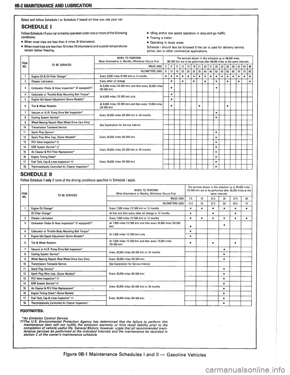
Select and follow Schedule I or Schedule I1 based on how you use your car:
SCHEDULE I
Follow Schedule I if your car is mainly operated under one or moreof the following Idling andlor low
speed operation in stop-and-go traffic.
conditions: Towing a trailer.
@ When most trips are less than 4 miles (6 kilometers).
Operating in dusty areas.
When most trips are less than 10 miles (16 kilometers) and outside temperatures
Schedule I should also be followed if the car is used for delivery service,
remain below freezing.
police, taxi or other commercial applications.
TO BE SERVICED
Every
30.000 miles I50 000 km)
Every 30,000 miles I50 000 km) or 36 months
Every
30,000 miles 150 000 km)
SCHEDULE ll
Follow Schedule II only if none of the driving conditions specified in Schedule I apply.
TO BE SERVICED
At
7 500 miles 12 500 km on1
FOOTNOTES:
I
*An Emission Control Service ttThe U.S. Environmental Protection Agency has determined that the failure to perform this
maintenance item will not nullifv the emission warrantv or limit recall liabilitv orior to the
completion of vehicle useful life. General Motors, however, urges that all recommended main-
tenance services be performed at the indicated intervals and the maintenance be recorded in
section C of the owner's
ma~ntenance schedule.
Figure OB-1 Maintenance Schedules I and I1 - Gasoline Vehicles
Page 20 of 1825
F CARLINE
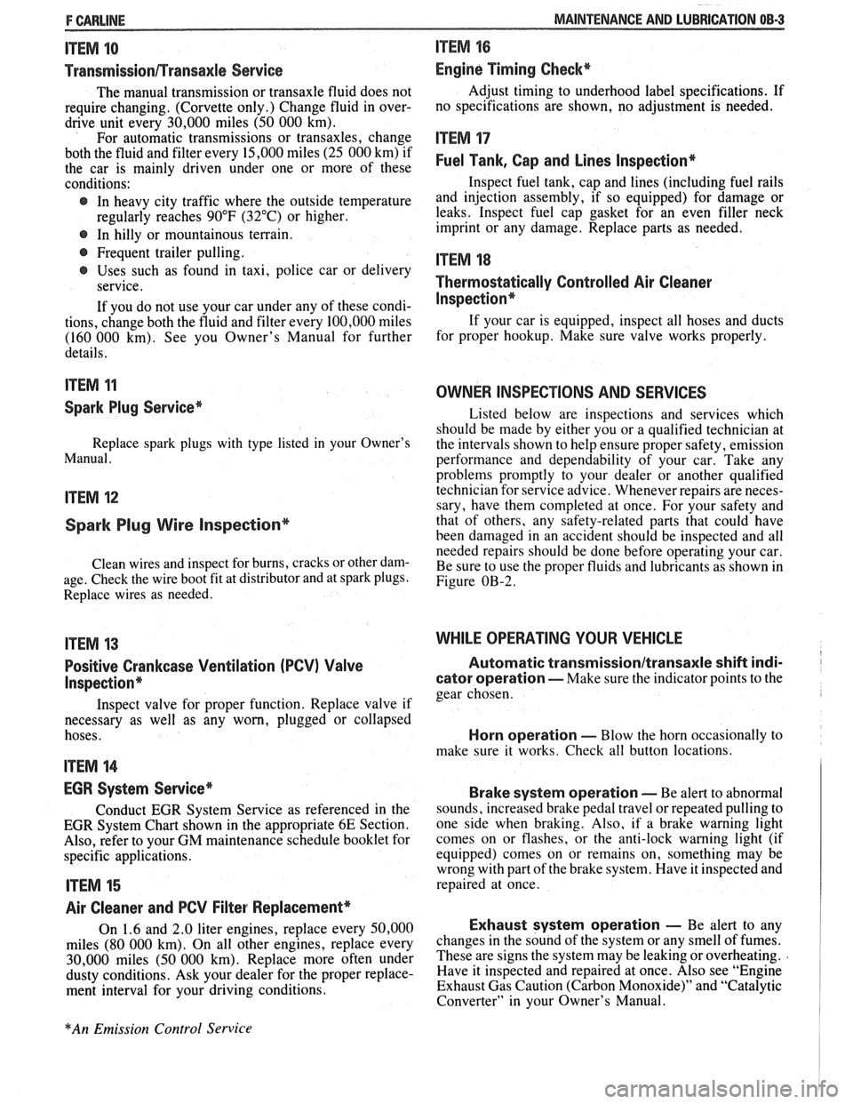
ITEM 10
TransmissionRransaxle Service
The manual transmission or transaxle fluid does not
require changing. (Corvette only.) Change fluid in over-
drive unit every 30,000 miles (50 000 km).
For automatic transmissions or transaxles, change
both the fluid and filter every 15,000 miles (25 000 km) if
the car is mainly driven under one or more of these
conditions:
@ In heavy city traffic where the outside temperature
regularly reaches 90°F (32°C) or higher.
@ In hilly or mountainous terrain.
@ Frequent trailer pulling.
@ Uses such as found in taxi, police car or delivery
service.
If you do not use your car under any of these condi-
tions, change both the fluid and filter every 100,000 miles
(160 000 km). See you Owner's Manual for further
details.
ITEM 11
Spark Plug Service*
Replace spark plugs with type listed in your Owner's
Manual.
ITEM 12
Spark Plug Wire Inspection*
Clean wires and inspect for burns, cracks or other dam-
age. Check the wire boot fit at distributor and at spark plugs.
Replace wires as needed.
ITEM 13
Positive Crankcase Ventilation (PCV) Valve
Inspection*
Inspect valve for proper function. Replace valve if
necessary as well as any worn, plugged or collapsed
hoses.
ITEM 14
EGR System Service*
Conduct EGR System Service as referenced in the
EGR System Chart shown in the appropriate 6E Section.
Also, refer to your GM maintenance schedule booklet for
specific applications.
ITEM 15
Air Cleaner and PCV Filter Replacement*
On 1.6 and 2.0 liter engines, replace every 50,000
miles (80 000 km). On all other engines, replace every
30,000 miles (50 000 km). Replace more often under
dusty conditions. Ask your dealer for the proper replace-
ment interval for your driving conditions.
MAINTENANCE AND LUBRICATION 08-3
ITEM 16
Engine Timing Check*
Adjust timing to underhood label specifications. If
no specifications are shown, no adjustment is needed.
ITEM 17
Fuel Tank, Cap and Lines Inspection*
Inspect fuel tank, cap and lines (including fuel rails
and injection assembly, if so equipped) for damage or
leaks. Inspect fuel cap gasket for an even filler neck
imprint or any damage. Replace parts as needed.
ITEM 18
Thermostatically Controlled Air Cleaner
Inspection*
If your car is equipped, inspect all hoses and ducts
for proper hookup. Make sure valve works properly.
OWNER INSPECTIONS AND SERVICES
Listed below are inspections and services which
should be made by either you or a qualified technician at
the intervals shown to help ensure proper safety, emission
performance and dependability of your car. Take any
problems promptly to your dealer or another qualified
technician for service advice. Whenever repairs are neces-
sary, have them completed at once. For your safety and
that of others, any safety-related parts that could have
been damaged in an accident should be inspected and all
needed repairs should be done before operating your car.
Be sure to use the proper fluids and lubricants as shown in
Figure OB-2.
WHILE OPERATING YOUR VEHICLE
Automatic transmissionltransaxle shift indi-
cator operation - Make sure the indicator points to the
gear chosen.
Horn operation - Blow the horn occasionally to
make sure it works. Check all button locations.
I
Brake system operation -- Be alert to abnormal
sounds, increased brake pedal travel or repeated pulling to
one side when braking. Also, if a brake warning light
comes on or flashes, or the anti-lock warning light (if
equipped) comes on or remains on, something may be
wrong with part of the brake system. Have it inspected and
repaired at once.
Exhaust system operation - Be alert to any
changes in the sound of the system or any smell of fumes.
These are signs the system may be leaking or overheating.
.
Have it inspected and repaired at once. Also see "Engine
Exhaust Gas Caution (Carbon Monoxide)" and "Catalytic
Converter" in your Owner's Manual.
*An Emission Control Service
Page 22 of 1825
MAINTENANCE AND LUBRICATION OB-5
Throttle linkage inspection -- Inspect for inter-
ference, binding, damaged or missing parts.
Engine drive belts inspection - Inspect all
belts for cracks, fraying and wear. Adjust or replace as
needed.
Rear axle service (if equipped) - Check gear
lubricant level and add if needed. For cars equipped with a
limited slip rear axle, fluid does not require changing
(except Caprice and Corvette
- change fluid and required
additive at first
7,500 miles (12 500 km). See your
Owner's Manual or "Recommended Fluids
& Lubricants
Chart" in this section.
IF YOU USE YOUR GAR TO PULL A TRAILER,
CHANGE GEAR LUBRICANT EVERY 7,500 MILES
(12 500 KM).
NOTICE: A large loss in this system may indicate a
problem. Have it inspected and repaired at once.
Power antenna - Clean and then lubricate power
antenna mast. The proper lubricant as shown in Figure
OB-2 should be used.
AT LEAST ONCE A YEAR
Lap and shoulder belts condition and opera-
tion
- Inspect belt system, including webbing, buckles,
latch plates, retractors, guide loops and anchors.
Moveable head restraint operation - On cars
with moveable restraints, make sure restraints stay in the
desired position. (See adjustment instructions in your
Owner's Manual.)
Seatback latch and recliner operation on
cars equipped
with recliner seat --- Be sure seat-
backs latch on those cars with folding seats using mechan-
ical latches. Make sure the recliner is holding by pushing
and pulling on the top of the
seatback while it is reclined.
See your Owner's Manual for seat operating information.
Spare tire and jack storage- Be alert to rattles
in rear of car. Make sure the space tire, all jacking equip-
ment, any tire inflator and any covers or doors are securely
stowed at all times. Oil jack ratchet or screw mechanism
after each use.
Key lock service - Lubricate key lock cylinder at
least annually.
Body lubrication service - Lubricate all body
door hinges including the tailgate or hatchback lid (if
equipped). Also lubricate the body hood, fuel door and
rear compartment hinges and latches including interior
glove box and counsel doors, and any folding seat
hardware.
"Fansmissionltransaxle neutral or clutch
starl switch operation
CAUnON: Before pedorming the follow-
ing safety switch check, be sure to have
enough room around the car. Then, firmly
apply both the parking brake (see your
Owner's Manual for procedure) and the
regular brakes. Do not use the accelerator pedal.
If the engine
starls, be ready to turn
off the ignition promptly. Take these pre-
cautions because the car could move
without warning and possibly cause per-
sonal injury or properly damage. On auto-
matic transmissionltransaxle cars, try to
starl the engine in each gear. The starler
should crank only in "Park" or "Neutral."
On manual transmissionltransaxle cars,
place the
shiR lever in "Neutral," push the
clutch halfway and try to starl. The starler
should crank only when the clutch is fully
depressed.
Steering column lock operation
- While
parked, try to turn key to "Lock" in each gear range. The
key should turn to "Lock" only when gear is in "Park" on
automatic or "Reverse" on manual
transmissionltransax-
le. On cars with key release lever, try to turn key toULock"
without depressing the lever. The key should turn to
"Lock" only with the key lever depressed. On all vehicles,
the key should come out only in "Lock."
Parking brake and transmissionltransaxle
"Park" mechanism operation
CAUT1ON:Before checking the holding
ability of the parking brake and automatic
transmissionltransaxle "Park" mecha-
nism, park on a fairly steep hill with
enough room for movement in the down-
hill direction. To reduce the risk of person-
al injury or property damage, be prepared
to apply the regular brakes promptly if the
car begins to move.
To check the parking brake, with the engine running and
transmission/transaxle in "Neutral." slowly remove foot
pressure from the regular brake pedal (until the car is held
by only the parking brake).
To check the automatic transmissionltransaxle "Park"
mechanism holding ability, release all brakes after shift-
ing the transmissionltransaxle to "Park."
ljnderbody flushing - At least every spring,
tlush from the underbody with plain water any corrosive
materials used for ice and snow removal and dust control.
Take care to thoroughly clean any areas where mud and
other debris can collect.
Sediment packed in closed areas
of the vehicle should be loosened before being flushed.
Engine cooling system service - Inspect
coolant and freeze protection. If dirty or rusty, drain, flush
and refill with new coolant. Keep coolant
at the proper
mixture as specified in your Owner's Manual. This pro-
vides proper freeze protection. corrosion inhibitor level
and engine operating temperature. Inspect hoses and re-
place if cracked. swollen or deteriorated. Tighten hose
clamps. Clean outside of radiator and air conditioning
condensor. Wash radiator filler cap and neck.
To help
ensure proper operation. a pressure test of both the cooling
system and cap is also recommended. (See maintenance
schedule charts in Figure
OB-l for the recommended
coolant change interval.)
Page 962 of 1825
DRIVEABILITY AND EMISSIONS . FUEL INJECIION 6E-1
DRBVEABILIW AND EMISSIONS
CONEENTS
General Information . Section 6E
Driveability and Emissions . Fuel Injected (TBI) . Section 6EZ
Driveability and Emissions . Fuel injected (PORT) . Section 6E3
..................... DRIVEABILITY 6E-1
........................ EMISSIONS 6E-1
MAINTENANCE SCHEDULE ............ 6E-1
VEHICLE EMISSIONS CONTROL
............. INFORMATION UBEL 6E-3
.................... INTRODUCTION 6E-3
.......... Electronic Engine Control 6E-3
What This Section Contains .......*. 6E-3
............. Blocking Drive Wheels 6E-3
.............. Cold Oxygen Sensor 6E-3
VISUAUPHYSICAL UNDERWOOD
..................... INSPECTION 6E-3
BASIC KNOWLEDGE REQUIRED ........ 6E-3
.............. Basic Electric Circuits 6E-3
Use of Circuit Testing Tools ......... 6E-4
Use of Digital Volt-Ohm Meter (DVM) . . 6E-4
DIAGNOSTIC INFORMATION .......... 6E-4
"Service Engine Soon" Light ........ 6E-4
Intermit . "Service Engine Soon" Light . . 6E-4
................... Trouble Codes 6E-4
.................. ALDL Connector 6E-4
Diagnostic Mode ................. 6E-4
Field Service Mode ................ 6E-5
............ Clearing Trouble Codes 6E-5
............. ECM Learning Ability 6E-5
DRIVEABILITY AND EMISSIONS ......... 6E-5
SECTIONS 6E2 and 6E3 SUMMARY ...... 6E-5
SECTION A ....................... 6E-6
Diagnostic Procedure Summary ...... 6E-6
ALDL "SCAN" TOOLS ................ 6E-6
Normal (Open) Mode ............. 6E-6
ALDL (1 OK. or Special) Mode ......... 6E-7
Factory Test (Backup or 3.9K) Mode .... 6E-7
DRIVEABILITY
The driveability diagnosis procedures apply to
various systems in current GM vehicles
. The
procedures assume that the vehicle worked right at
one time and the problem is due to time, wear. dirt or
other causes
. Start with the introduction that follows .
This will describe a systematic diagnostic procedure .
Any system disconnected during diagnosis should
be reconnected
. This includes wires, hoses. linkage.
etc . When removing air cleaner. plug hose fittings
that could cause an air leak
.
"SCAN" TOOLS LIMITATIONS AND USE ... 6E-7
Intermittent Conditions ........... 6E-7
"SCAN" TOOL POSITIONS ............ 6E-7
SECTION B . DRIVEABILITY SYMPTOMS . . 6E-10
SECTION C- COMPONENT SYSTEMS ..... 6E-10
Electronic Control Module (ECM) ..... 6E-10
Fuel Control System ............... 6E-10
Electric Fuel Pump (In-tank) ........ 6E-10
....... Evaporative Emission Control 6E-10
Electronic Spark Timing (EST) ....... 6E-10
....... Electronic Spark Control (ESC) 6E-10
Air Injection Reaction (A.I.R.). ........ 6E-10
......... Early Fuel Evaporation (EFE) 6E-10
Exhaust Gas Recirculation (EGR) ...... 6E-11
Transmission Convefler Clutch (TCC) . . 6E-11
.............. Shift Light Control ; . 6E-I I
................ NC Clutch Control 6E-11
........ Electric Cooling Fan Control 6E-11
Positive Crankcase Ventilation (PCV)
...... or Crankcase Ventilation (CV) 6E-11
Thermostatic Air Cleaner (THERMAC) . . 6E-11
ABBREVIATIONS & GLOSSARY OF TERMS .. 6E-1 1
............ WIRING HARNESS SERVICE 6E-14
......................... GENERAL 6E-14
WIREHARNESS.... ............*.... 6E-15
CONNECTORS .....e..e..ee...~.e.. 6E-15
................... Weather-Pack 6E-15
.................. Compact Three 6E-16
Metri-Pack Series 150 . Terrn'l Removal 6E-16
...................... Micro-Pack 6E-16
...... TOOLS NEED TO SERVICE SYSTEM 6E-17
GENERAL SPECIFICATIONS ............. 6E-23
EMISSIONS
The exhaust emission control systems used on
General Motors engines perform a specific function to
lower exhaust emissions while maintaining good fuel
economy and driveability
.
MAINTENANCE SCHEDULE
Refer to the General Motors Maintenance
Schedule in Section
"OB" of the Chassis Service
Manual for the maintenance service that should be
performed to retain emission control performance
.
Page 1677 of 1825
96.4 MISCELLANEOUS ACCESSORIES
DASH AND CONSOLE MOUNTED ACCESSORY
SWITCHES
Installation for various dash and console
mounted accessory switches is shown in Section
8C.
GENERAL DESCRIPIIOM
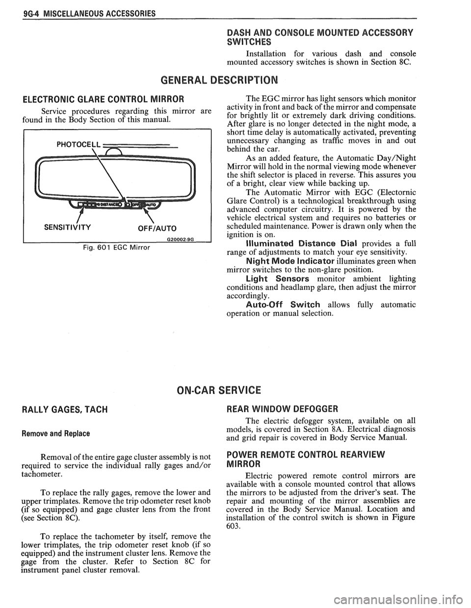
ELECTRONIC GLARE CONTROL MIRROR
Service procedures regarding this mirror are
found in the Body Section of this manual.
Fig. 601 EGC Mirror
The EGC mirror has light sensors which monitor
activity in front and back of the mirror and compensate
for brightly lit or extremely dark driving conditions.
After glare is no longer detected in the night mode, a
short time delay is automatically activated, preventing
unnecessary changing as traffic moves in and out
behind the car.
As an added feature, the Automatic
Day/Night
Mirror will hold in the normal viewing mode whenever
the shift selector is placed in reverse. This assures you
of a bright, clear view while backing up.
The Automatic Mirror with EGC (Electornic
Glare Control) is a technological breakthrough using
advanced computer circuitry. It is powered by the
vehicle electrical system and requires no batteries or
scheduled maintenance. Power is drawn only when the
ignition is on.
Illuminated Distance Dial provides a full
range of adjustments to match your eye sensitivity.
Night Mode Indicator illuminates green when
mirror switches to the non-glare position.
Light Sensors monitor ambient lighting
conditions and
headlamp glare, then adjust the mirror
accordingly.
Auto-Off Switch allows fully automatic
operation or manual selection.
ON-CAR SERVICE
RALLY GAGES, TACH REAR WINDOW DEFOGGER
Remove
and Replace
The electric defogger system, available on all
models, is covered in Section
8A. Electrical diagnosis
and grid repair is covered in Body Service Manual.
Removal of the entire gage cluster assembly is not
POWER RmOTE CONTROL REARVIEW
required to service the individual rally gages and/or MIRROR
tachometer.
Electric powered remote control mirrors are
available with a console mounted control that allows
To replace the rally gages, remove the lower and the
mirrors to be adjusted from the driver's seat. The
upper trimplates. Remove the trip odometer reset knob repair
and mounting of the mirror assemblies are
(if so equipped) and gage cluster lens from the front covered in
the Body Service Manual. Location and
(see Section
8C). installation of the control switch is shown in Figure
603.
To replace the tachometer by itself, remove the
lower trimplates, the trip odometer reset knob (if so
equipped) and the instrument cluster lens. Remove the
gage from the cluster. Refer to Section
8C for
hstrument panel cluster removal.
Page 1683 of 1825
1 H-2 GENERAL INFORMATION - F STYLE
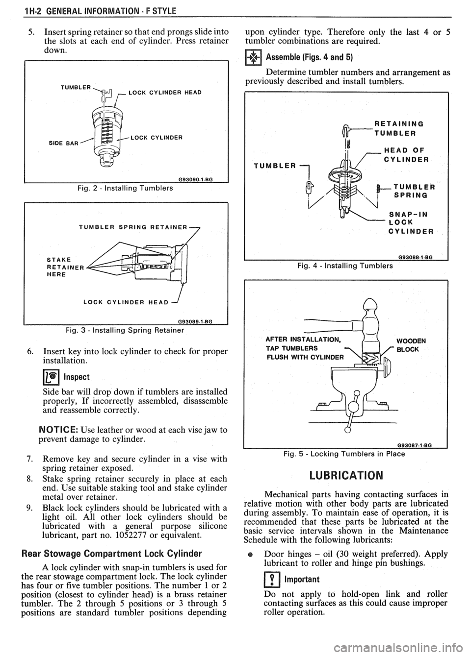
5. Insert spring retainer so that end prongs slide into
upon cylinder type. Therefore only the last 4 or 5
the slots at each end of cylinder. Press retainer
tumbler combinations are required.
down.
TUMBLER \m , LOCK CYLINDER HEAD
SIDE BAR LOCK CYLINDER
Fig.
2 - Installing Tumblers
TUMBLER SPRING RETAINER
LOCK CYLINDER HEAD
Fig.
3 - Installing Spring Retainer
6. Insert key into lock cylinder to check for proper
installation.
Inspect
Side bar will drop down if tumblers are installed
properly, If incorrectly assembled, disassemble
and reassemble correctly.
NOTICE: Use leather or wood at each vise jaw to
prevent damage to cylinder.
7. Remove key and secure cylinder in a vise with
spring retainer exposed.
8. Stake spring retainer securely in place at each
end. Use suitable staking tool and stake cylinder
metal over retainer.
9. Black lock cylinders should be lubricated with a
light oil. All other lock cylinders should be
lubricated with a general purpose silicone
lubricant, part no. 1052277 or equivalent.
Assemble (Figs. 4 and 5)
Determine tumbler numbers and arrangement as
previously described and install tumblers,
TUMBLER
I CYLINDER I
Fig. 4 - Installing Tumblers
AFTER INS WOODEN
TAP TUMBLERS BLOCK
FLUSH
WITH CYLINDER
Fig. 5 - Locking Tumblers in Place
LUBRICATION
Mechanical parts having contacting surfaces in
relative motion with other body parts are lubricated
during assembly. To maintain ease of operation, it is
recommended that these parts be lubricated at the
basic service intervals shown in the Maintenance
Schedule with the following lubricants:
Rear Stowage Compartment Lock Cylinder Door hinges - oil (30 weight preferred). Apply
A lock cylinder with snap-in tumblers is used for lubricant
to roller and hinge pin bushings.
the rear stowage compartment lock. The lock cylinder
Important has four or five tumbler positions. The number 1 or 2
position (closest to cylinder head) is a brass retainer Do
not apply to hold-open link and roller
tumbler. The
2 through 5 positions or 3 through 5 contacting
surfaces as this could cause improper
positions are standard tumbler positions depending roller operation.