1988 PONTIAC FIERO wiring
[x] Cancel search: wiringPage 649 of 1825
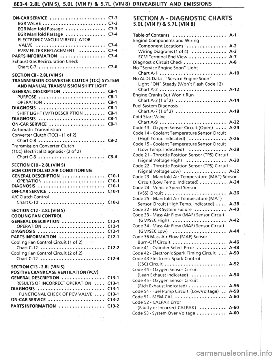
6E3-4 2.8L (VIN S) . 5.OL (VIN F) & 5.7L (VIN 8) DRIVEABILITY AND EMISSIONS
ON-CAR SERVICE ..................... C7-3
EGRVALVE
........................ C7-3
EGR Manifold Passage
............... C7-3
EGR Manifold Passage
............... C7-4
ELECTRONIC VACUUM REGULATOR
VALVE
.......................... C7-4
EVRV FILTER REPLACEMENT
.......... C7-4
PARTS INFORMATION
................. C7-4
Exhaust Gas Recirculation Check
Chart C-7
......................... C7-6
SECTION
C8 . 2.8L (VIN S)
TRANSMISISON CONVERTER CLUTCH (TCC) SYSTEM
AND MANUAL TRANSMISSION SHIFT LIGHT
GENERAL DESCRIPTION
................ C8-1
PURPOSE ......................... C8-1
OPERATION ....................... C8-1
DIAGNOSIS
......................... C8-1
SHIFT LIGHT (M/T) DESCRIPTION ........ C8-1
DIAGNOSIS
......................... C8-1
ON-CAR SERVICE ..................... C8-1
Automatic Transmission
Converter Clutch (TCC)
. (1 of 2)
Chart C-8
......................... C8-2
Transmission Converter Clutch
(TCC) Electrical Diagnosis
. (2 of 2)
Chart C-8
......................... C8-4
SECTION C10 . 2.8L (WIN S)
ECM CONTROLLED AIR CONDITIONING
GENERAL DESCRIPTION
................ C10-1
OPERATION ....................... C10-1
DIAGNOSIS ......................... C10-1
ON-CARSERVICE ..................... C10-1
FJC Clutch Control
Chart C-
1 0 ........................ C10-2
SECTION C12 . 2.8L (VlN S)
COOLING FAN CONTROL
GENERAL DESCRIPTION
................ C12-1
OPERATION ....................... C12-1
DIAGNOSIS
......................... C12-1
PARTS INFORMATION ................. C12-1
Cooling Fan Control Circuit (1 of 2)
Chart
C- 12 ........................ C12-2
Cooling Fan Control Circuit (2 of 2)
Chart C-12
........................ C12-4
SECTION C13
. 2.8L (WIN S)
POSITIVE CRANKCASE VENTILATION (PCV)
GENERAL DESCRIPTION
................ C13-1
RESULTS OF INCORRECT OPERATION
.... C13-1
DIAGNOSIS
......................... C13-1
FUNCTIONALCHECK OF PCV VALVE .... C13-1
ON-CAR SERVICE
..................... C13-2
PARTS INFORMATION
................. C13-2
SEC"T0N A . DIAGNOSTIC CHARTS
5.OL (VIN F) & 5.7L (VIN 8)
.................... Table of Contents A-1
Engine Components and Wiring
............... Component Locations A-2
Wiring Diagrams
(1 of 4) ............. A-3
ECM Terminal End View
.............. A-7
Diagnostic Circuit Check
................ A-8
No "Service Engine Soon" Light
......................... Chart A-1 A-10
No ALDL Data
. "Service Engine Soon"
Light "ON" Steady (Won't Flash Code 12)
Chart A-2
......................... A-12
Eng~ne Cranks But Won't Run
Chart A-3
(1 of 2) ................... A-14
Fuel System
Diagnos~s
Chart A-7 (1 of 2) ................... A-18
Cold Start Valve
Chart A-9
......................... A-22
Code 13
. Oxygen Sensor Circuit (Open) .... A-24
Code 14
. Coolant Temperature Sensor Circuit
(High Temp
. Indicated) .............. A-26
Code
1 5 . Coolant Temperature Sensor C~rcuit
. .............. (Low Temp Ind~cated) A-28
Code 21
. Throttle Pos~tlon Sensor (TPS) Circuit
(Signal Voltage High)
............... A-30
Code 22
. Throttle Pos~t~on Sensor (TPS) Circuit
................ (Signal Voltage Low) A-32
Code 23
. Manifold Air Temperature (MAT) Sensor
C~rcuit (Low Temp . Indicated) .......... A-34
Code 24
. Vehicle Speed Sensor
....................... (VSS) Circuit A-36
Code 25
. Manifold Air Temperature (MAT)
Sensor Circuit (High Temp
. Indicated) .... A-38
. ............ Code 32 EGR System Failure A-40
Code 33
. Mass Air Flow (MAF) Sensor Circuit
.................... (GMISECHlgh) A-42
Code 34
. Mass Air Flow (MAF) Sensor Circu~t
.................... (GMISEC Low) A-44
Code 36 Mass Air Flow
(MAF) Sensor
.. ..... ........... Burn-Off Circuit , , A-46
. ........... Code 41 Cyl~nder Select Error A-48
... . Code 42 Electronic Spark Timing Circuit A-50
Code 43 Electronic Spark Control
(ESC)
C~rcuit ....................... A-52
Code 44
. Oxygen Sensor Circu~t
(Lean Exhaust lnd~cated) ............. A-54
Code 45
. Oxygen Sensor Circuit
(Rich Exhaust Indicated)
.............. A-56
Code 54
. Fuel Pump C~rcuit (Lowvoltage) . . 14-58
. ................... Code 51 MEM-CAL A-60
Code 52
. CALPAK Error
.......... (Faulty or Incorrect CALPAK) A-60
. ........... Code 53 System Over Voltage A-60
Page 654 of 1825
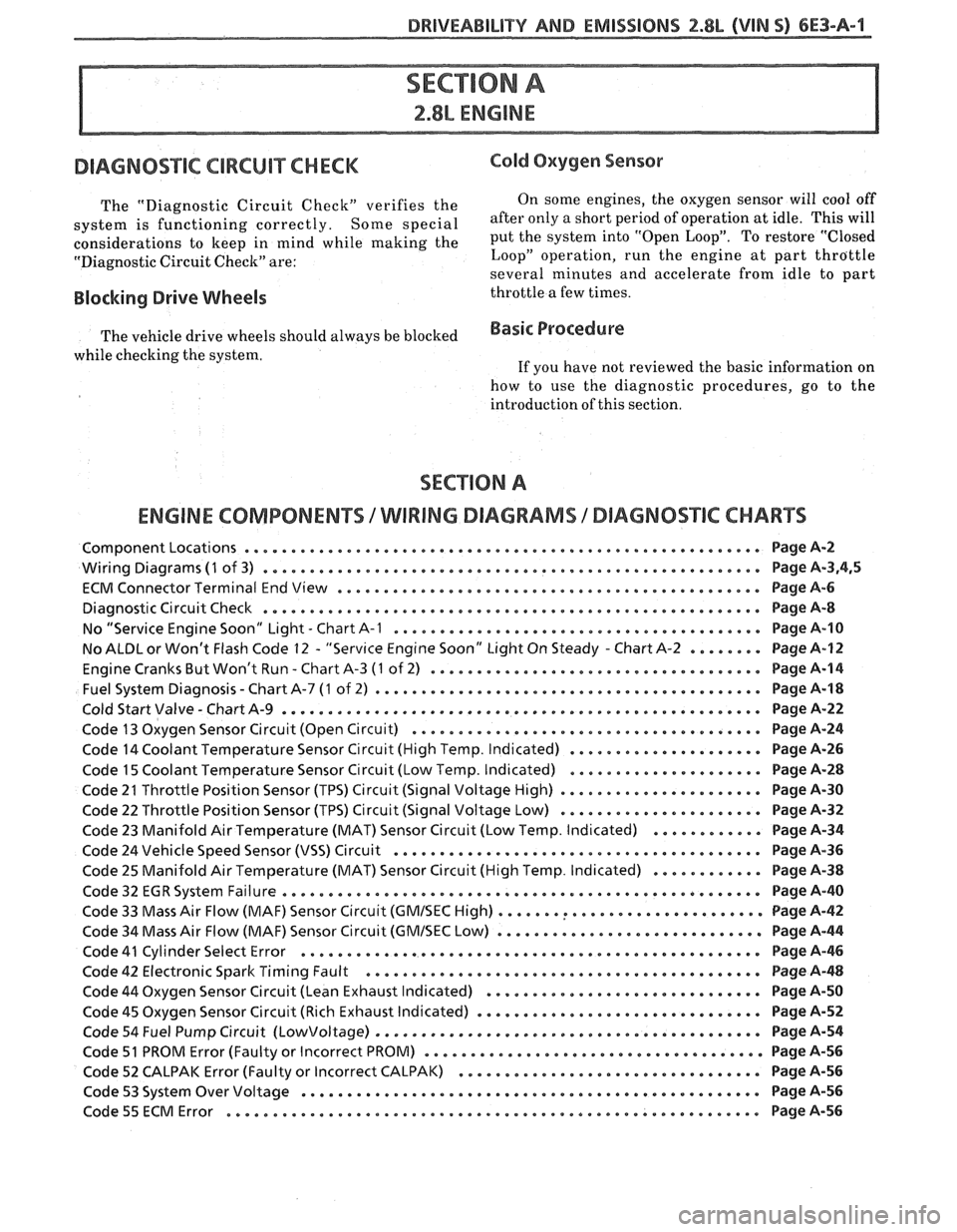
DRIVEABILITY AND EMISSIONS f.8b (VIN S) 6E3-A-1
Cold Oxygen Sensor
The "Diagnostic Circuit Check" verifies the On some engines.
the oxygen sensor will cool off
system is functioning correctly . some special after only a short period of operation at idle . This will
considerations to keep in mind while making the put the system into "Open Loop" . To restore "Closed
"Diagnostic Circuit Check" are: Loop"
operation. run the engine
at part throttle
several minutes and accelerate from idle to part
Blocking Drive Wheels throttle a few times .
The vehicle drive wheels should always be blocked Basic Procedure
while checking the system . If you have not reviewed the basic information on
how to
use the diagnostic procedures. go to the
introduction of this section
.
ENGINE COMPONENTS /WIRING DIAGRAMS / DIAGNOSTIC CHARTS
ComponentLocations ........................................................ PageA-2
Wiring Diagrams (1 of 3) ...................................................... Page A.3.4. 5
ECM Connector Terminal End View
.............................................. Page A-6
Diagnostic Circuit Check
...................................................... Page A-8
No "Service Engine Soon" bight
. Chart A-1 ........................................ Page A-10
No
ALBL or Won't Flash Code 12 . "Serv~ce Engine Soon" Light On Steady . Chart A-2 ........ Page A-12
. Engine Cranks But Won't Run Chart A-3 (1 of 2) .................................... Page 8-14
. Fuel System Diagnosis Chart A-7 (1 of
2) .......................................... Page A-18
Cold Start Valve
. Chart A-9 .................................................... Page A-22
Code 13 Oxygen Sensor Circuit (Open Circuit)
...................................... Page A-24
Code 14 Coolant Temperature Sensor Circuit (High Temp
. Indicated) ..................... Page A-26
Code 15 Coolant Temperature Sensor Circuit (Low Temp
. Indicated) ..................... Page A-28
Code 21 Throttle Position Sensor (TPS) Circuit (Signal Voltage High)
...................... Page A-30
Code 22 Throttle Position Sensor (TPS) Circuit (Signal Voltage Low)
...................... Page A-32
Code 23 Manifold Air Temperature (MAT) Sensor Circuit (Low Temp
. Indicated) ............ Page A-34
Code 24 Vehicle Speed Sensor (VSS) Circuit
........................................ Page A-36
Code
25 Manifold Air Temperature (MAT) Sensor Circuit (High Temp . Indicated) ............ Page A-38
Code 32
EGR System Failure .................................................... Page A-40
Code 33 Mass Air Flow (MAF) Sensor Circuit
(GMISEC High) ............................. Page A-42
Code 34 Mass Air Flow (MAF) Sensor Circuit
(GMISEC bow) ............................. Page 8-44
Code
41 Cylinder Select Error .................................................. Page A-46
Code 42 Electronic Spark Timing Fault
................... .... .................... Page 8-48
Code 44 Oxygen Sensor Circuit (Lean Exhaust Indicated)
.............................. Page A-50
Code
45 Oxygen Sensor Circuit (Rich Exhaust Indicated) ............................... Page A-52
Code 54 Fuel Pump Circuit
(Lowvoltage) .......................................... Page A-54
Code
51 PROM Error (Faulty or Incorrect PROM) ..................................... Page A-56
Code 52 CALPAK Error (Faulty or Incorrect CALPAK)
................................. Page 44-56
Code 53 System Over Voltage .................................................. Page A-56
Code55ECMError ............................O.~o.~.~e.~e~e.~e....... .. PageA-56
Page 656 of 1825
BRlVEABlLlTY AND EMISSIONS 2.8L (VIN 5) 6E3-A-3
ENGINE GND'S BACK VIEW
OF
CONNECT OR
TO VSS BUFFER
OXYGEN SENSOR
ENGINE GND.
MANIFOLD AIR
TEMPERATURE
4 WAY INJ.
JPR. CONN.
7-14-87
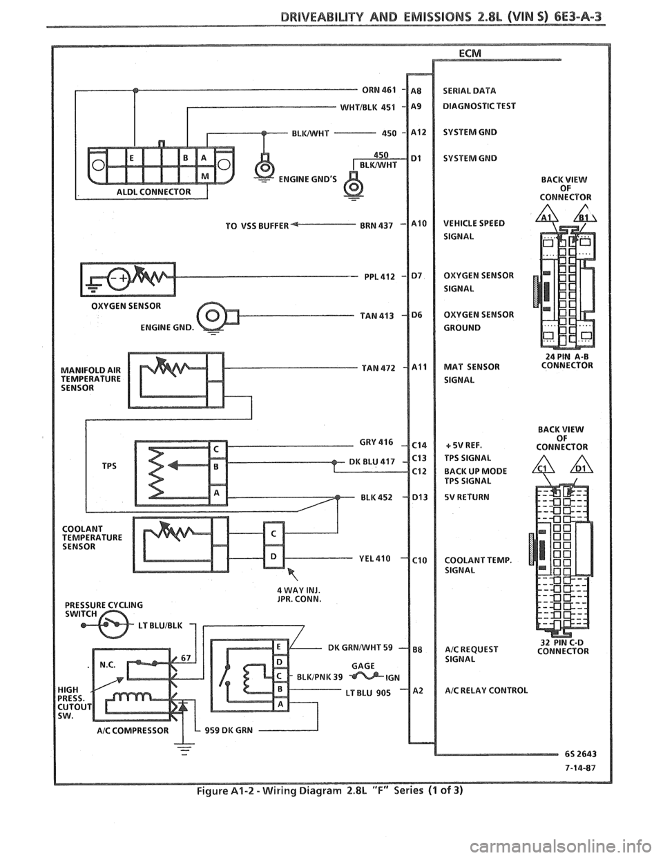
Figure A1-2 -Wiring Diagram 2.8L "F" Series (1 of 3)
Page 658 of 1825
DRIVEABILITY AND EMISSIONS 2.8L (VIN S) 6E3-A-5
ECM
BRAKE SWITC
BACK
VIEW OF
AIR DIVERT SOLENOID
MANUALITRANS
IGNITION 12V
TANMIHT 250 ALTERNATOR
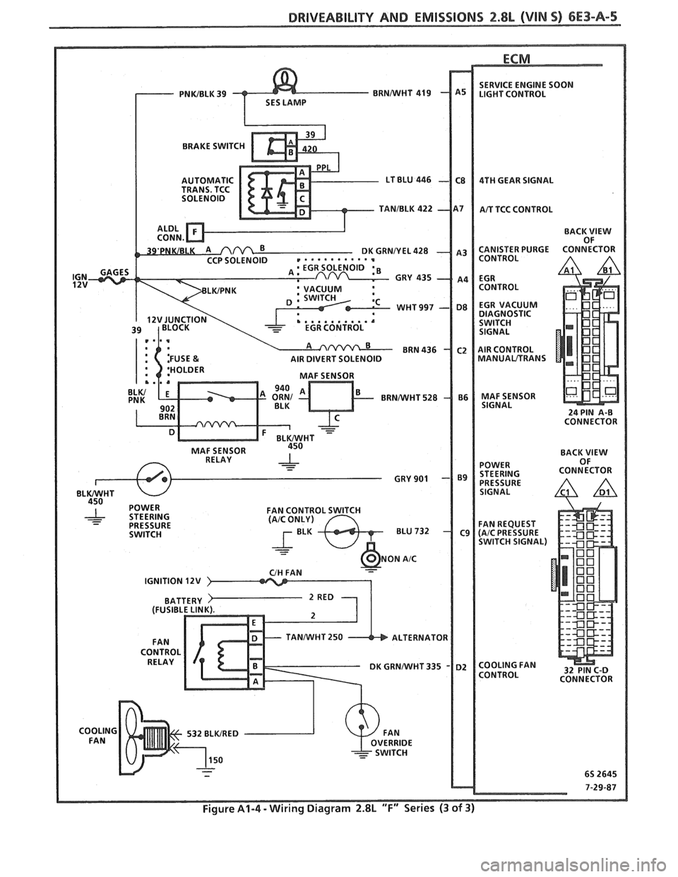
Figure A1-4 - Wiring Diagram 2.8L "F" Series (3 of 3)
Page 663 of 1825

6E3-A-"I 2.8L (VlN S) DRIVEABILITY AND EMlSSlONS
TO OIL PRESS. SW.
&FUEL PUMP RELAY
FUSE
81 HOLDER BATTERY 12 V .. m.. . n.
. . . . . . . . FUSIBLE LINK
439 PNWBLK
419 BRNNVHT
SERIAL
DATA
451
WHTJBLK
450 BLKNVHT
ALDL CONNECTOR
NO "SERVICE ENGlNE SOON" "LIGHT
2.8b (VIM 5) 'T" "SERIES (PORT)
Circuit Description:
There should always be a steady "Service Engine Soon" light when the ignition is "ON" and engine stopped.
Battery is supplied directly to the light bulb. The electronic control module
(ECNI) will control the light and
turn it "ON" by providing a ground path through CKT 419 to the ECM.
Test Description: Numbers below refer to circled
numbers on the diagnostic chart.
1. If the fuse in holder is blown refer to facing page of
Code
54 for complete circuit.
2. Using a test light connected to 12 volts probe each
of the system ground circuits to be sure a good
ground is present. See ECM terminal end view in
front of this section for
ECM pin locations of
ground circuits.
Diagnostic Aids:
Engine runs OK, check:
@ Faulty light bulb.
@ CKT 419 open.
@ Gage fuse blown.
This will result in no oil or
generator lights, seat belt reminder, etc. Engine
cranks but will not run.
@ Continuous battery - fuse or fusible link open.
@ ECM ignition fuse open.
@ Battery CKT 340 to ECM open.
@ Ignition CKT 439 to ECM open.
e Poor connection to ECM.
Solenoids and relays are turned "ON"
and "OFF"
by the ECM, using internal electronic switches called
"drivers". Each driver is part of a group of four called
"Quad-Drivers". Failure of one driver can damage
any other driver in the set. Solenoid and relay coil
resistance must measure more than 20 ohms. Less
resistance will cause early failure of the ECM
"driver".
Before replacing ECM, be sure to check the coil
resistance of all solenoids and relays controlled by the
ECM. See ECM wiring diagram for the
solenoid(s)
and relay(s) and the coil terminal identification.
Page 665 of 1825
6E3-A-92 2.8b (VIN SI DRIVEABILITY AND EMISSIONS
TO OIL PRESS. SW.
&FUEL PUMP RELAY
FUSE
& HOLDER BATTERY 12
V
.. am.. . FUSIBLE LINK 15 WAY
439
PNWBLK
- 419 BUNNVHT
SERIAL DATA
451
WHTIBLK
450 BLWHT
ALDL CONNECTOR
CHART A-2
NO ALDL OR WONT FLASH CODE 12
""SERVICE ENGlNE SOON" MGHT ""8N13SPEADY
2.8L (VIN S) ""FYSERlES (PORT)
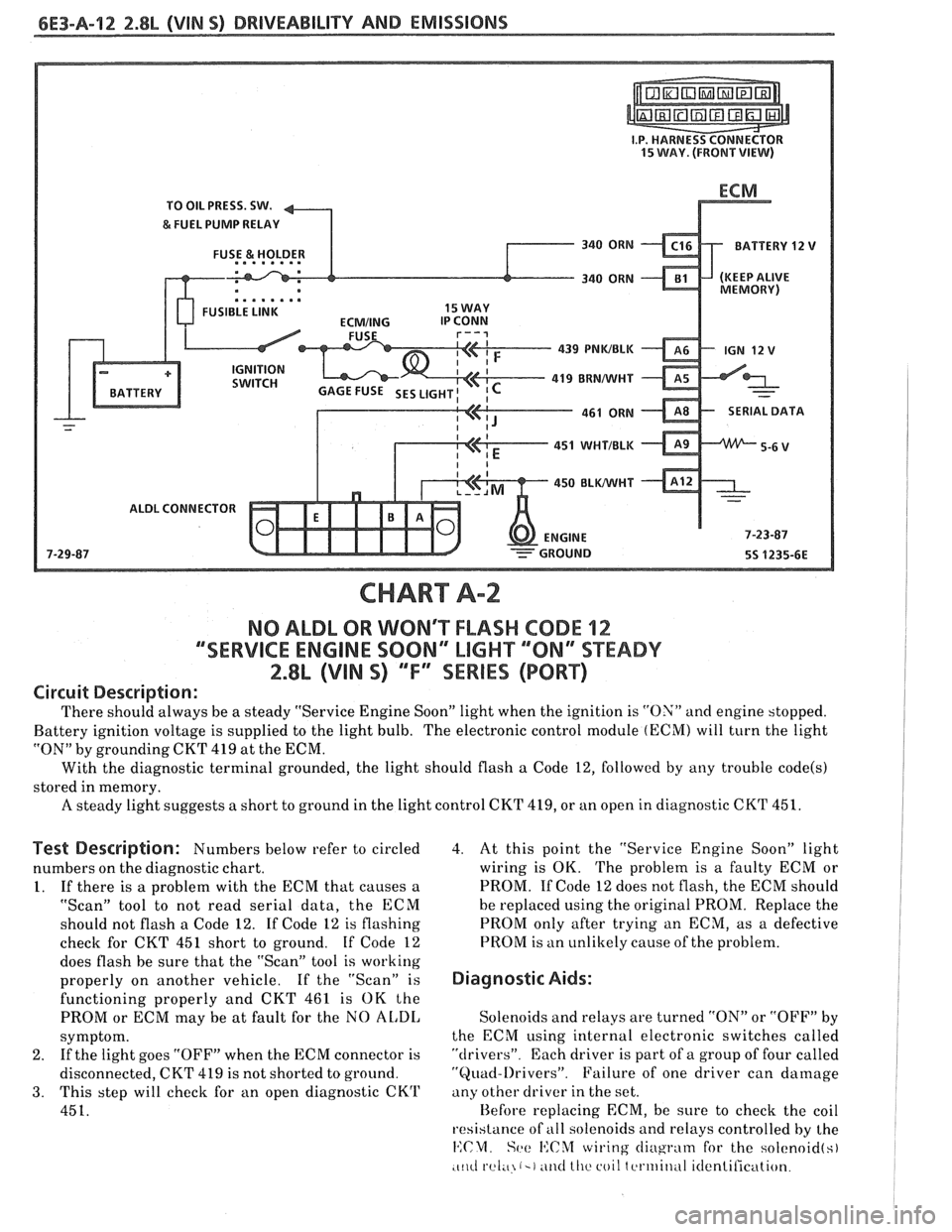
Circuit Description:
There should always be a steady "Service Engine Soon" light when the ignition is "ON" and engine stopped.
Battery ignition voltage is supplied to the light bulb. The electronic control module
(ECM) will turn the light
"ON" by grounding CKT
419 at the ECM.
With the diagnostic terminal grounded, the light should flash
a Code 12, followed by any trouble code(s)
stored in memory.
A steady light suggests a short to ground in the light control CKT 419, or an open in diagnostic CKT 451.
Test Description: Numbers below refer to circled
numbers on the diagnostic chart.
1. If there is a problem with the ECM that causes a
"Scan" tool to not read serial data, the ECM
should not flash a Code 12. If Code 12 is flashing
check for CKT
451 short to ground. If Code 12
does flash be sure that the "Scan" tool is working
properly on another vehicle. If the "Scan" is
functioning properly and CKT 461 is OK the
PROM or ECM may be at fault for the NO
AL,DI,
symptom.
2. If
the light goes "OFF" when the ECM connector is
disconnected, CKT 419 is not shorted to ground.
3. This step will check for an open diagnostic CKrl'
451.
4. At this point the "Service Engine Soon" light
wiring is OK. The problem is a faulty ECM or
PROM. If Code 12 does not flash, the ECM should
he replaced using the original PROM. Replace the
PROM only after trying an ECM, as a defective
PROM is an unlikely cause of the problem.
Diagnostic Aids:
Solenoids and relays are turned "ON" or "OFF" by
the ECM using internal electronic switches called
"drivers". Each driver is part of a group of four called
"Quad-l)rivers". Failure of one driver can damage
any other driver in the set.
Hefore replacing ECM, be sure to check the coil
resistance of
all solenoids and relays controlled by the
14:CM. Set: I':C%f wiring cliugrntn for the solcnoid(s)
.c~~cl rel;~ (-1 ~ititl lllc coil tcrtriitlul itlentilication.
Page 669 of 1825
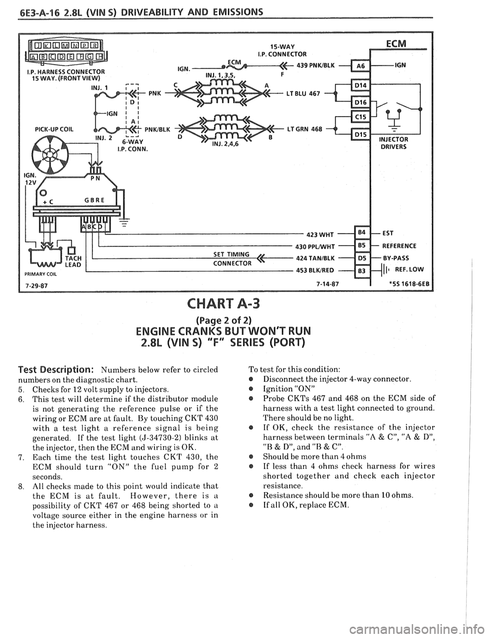
CHART A-3
(Page 2 of 2)
ENGINE CRANKS BUT WONT WN
2.8L (VIN S) ""FYSERIES (PORT)
Test Description: Numbers below refer to circled
numbers on the diagnostic chart.
5. Checks for 12 volt supply to injectors.
6. This
test will determine if the distributor module
is not generating the reference pulse or if the
wiring or ECM are at fault. By touching CKT 430
with a test light a reference signal is being
generated. If the test light
(5-34730-2) blinks at
the injector, then the ECM and wiring is OK.
7. Each time
the test light touches CKT 430, the
ECM should turn "ON" the fuel
punlp for 2
seconds.
8. All
checks made to this point would indicate that
the ECM is at fault. However, there is
a
possibility of CKT 467 or 468 being shorted to a
voltage source either in the engine harness or in
the injector harness. To
test for this condition:
@ Disconnect the injector 4-way connector.
@ Ignition "ON"
Probe
CKTs 467 and 468 on the ECM side of
harness with a test light connected to ground.
There should be no light.
@ If OK, check the resistance of the injector
harness between terminals
"A & C", "A & D",
"B & D", and .'B & C".
@ Should be more than 4 ohms
@ If less than 4 ohms check harness for wires
shorted together and check each injector
resistance.
@ Resistance should be more than 10 ohms.
@ If all OK, replace ECM.
Page 677 of 1825
6E3-A-24 2.8L (WIN 5) DRIVEABILITY AND EMISSIONS
OXYGEN ( 02) SENSOR
-
CODE 13
OXYGEN SENSOR CIRCUIT
(OPEN CIRCUIT)
2.8L (VIN S) ""FXSERlES (PORT)
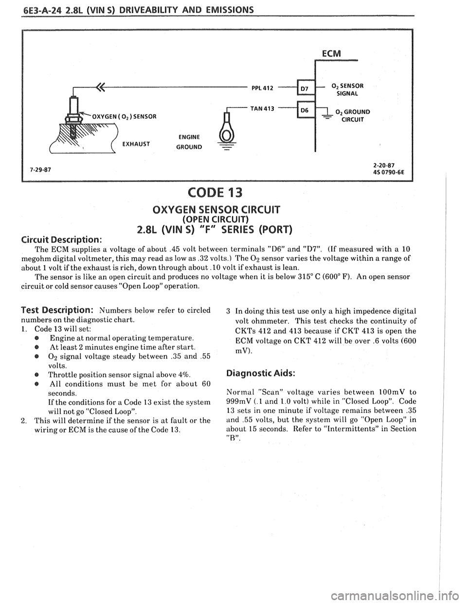
Circuit Description:
The ECM supplies a voltage of about .45 volt between terminals "D6" and "D7". (If measured with a 10
megohm digital voltmeter, this may read as low as .32 volts.) The
02 sensor varies the voltage within a range of
about
1 volt if the exhaust is rich, down through about. 10 volt if exhaust is lean.
The sensor is like an open circuit and produces no voltage when it is below 315" C
(600" F). An open sensor
circuit or cold sensor causes "Open Loop" operation.
Pest Description: Numbers below refer to circled
3 In doing this test use only a high impedence digital
numbers on the diagnostic chart.
volt ohmmeter. This test checks the continuity of
1. Code 13 will set:
CKTs 412 and 413 because if CKT 413 is open the @ Engine at normal operating temperature.
ECM voltage on CKT 412 will be over .6 volts (600 @ At least 2 minutes engine time after start. mV). @ 02 signal voltage steady between .35 and .55
volts.
@ Throttle position sensor signal above 4%.
@ All conditions must be met for about 60
seconds. If the conditions for a Code 13 exist the system
will not go "Closed Loop".
2. This will determine if the sensor is at fault or the
wiring or ECM is the cause of the Code 13.
Diagnostic Aids:
Normal "Scan" voltage varies between 1OOmV to
999mV (.1 and 1.0 volt) while in "Closed Loop".
Code
13 sets in one minute if voltage remains between .35
and .55 volts, but the system will go "Open Loop" in
about 15 seconds, Refer to "Intermittents" in Section
"R".