1988 PONTIAC FIERO wiring
[x] Cancel search: wiringPage 523 of 1825
6E2-A-32 S.OL (VIN E) DRIVEABILITY AND EMISSIONS
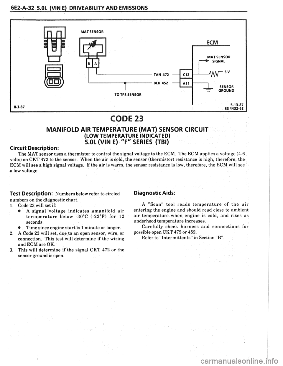
MAT SENSOR
MAT SENSOR
TAN
472 C12
BLK 452 - ~11
- GROUND
TO TPS SENSOR
CODE 23
MANIFOLD AIR TEMPERATURE (MAT) SENSOR CIRCUIT
(LOW TEMPERATURE INDICATED)
5.OL (VIN E) "F" SERIES (TBI)
Circuit Description:
The MAT sensor uses a thermistor to control the signal voltage to the ECM. The ECM applies a voltage (4-6
volts) on CKT 472 to the sensor. When the air is cold, the sensor (thermistor) resistance is high, therefore, the
ECM will see a high signal voltage. If the air is warm, the sensor resistance is low, therefore, the
E:CM will see
a low voltage.
i
Test Description: Numbers below refer to circled
numbers on the diagnostic chart.
1. Code 23 will set if:
@ A signal voltage indicates amanifold air
termperature below -30°C
(-22°F) for 12
seconds.
@ Time since engine start is 1 minute or longer.
2. A Code 23 will set, due to an open sensor, wire, or
connection. This test will determine if the wiring
and ECM are OK.
3. This will determine if the signal CKT 472 or the
sensor ground is open.
Diagnostic Aids:
A "Scan" tool reads temperature of the air
entering the engine and should read close to ambient
air temperature when engine is cold, and rises as
underhood temperature increases.
Carefully check harness and connections for
possible open CKT
472 or 452.
Refer to "Intermittents" in Section "B".
Page 525 of 1825
6EZ-A-34 5.OL (WIN E) DRIVEABILITY AND EMISSIONS
ECM
I.P.
8RN 437
K 7 PIN SIGNAL
PIN SWITCH
r ELK450 12v
1 CLOSED IN - 15- WAY .I.P. CONNECTOR - - PARK OR NEUTRAL I
CODE 24
VEHICLE SPEED SENSOR (VSS) CIRCUIT
5.OL (VIN E) "F" SERIES (TBI)
Circuit Description:
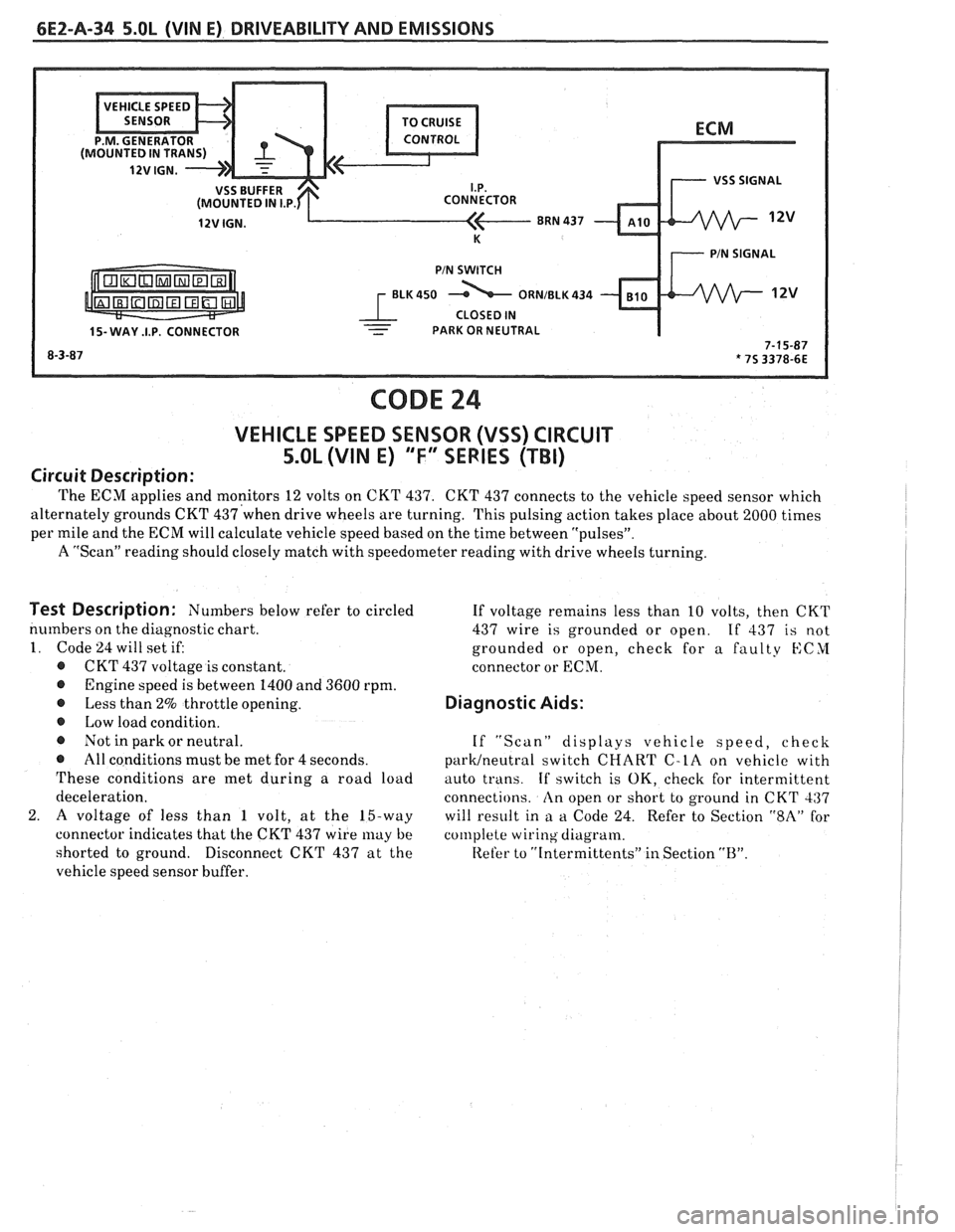
The ECM applies and monitors 12 volts on CKT 437. CKT 437 connects to the vehicle speed sensor which
alternately grounds CKT
437'when drive wheels are turning. This pulsing action takes place about 2000 times I
per mile and the ECM will calculate vehicle speed based on the time between "pulsesJ'.
A "Scan" reading should closely match with speedometer reading with drive wheels turning.
I
Test Description: Numbers below refer to circled
numbers on the diagnostic chart.
1. Code 24 will set if:
@ CKT 437 voltage is constant.
@ Engine speed is between 1400 and 3600 rpm.
@ Less than 2% throttle opening.
@ Low load condition.
@ Not in park or neutral.
@ All conditions must be met for 4 seconds.
These conditions are met during a road load
deceleration.
2.
A voltage of less than 1 volt, at the 15-way
connector indicates that the CKT 437 wire
may be
shorted to ground.
Disconnect CKT 437 at the
vehicle speed sensor buffer. If
voltage remains less than 10 volts, then CKT
437 wire is grounded or open.
If 437 is not
grounded or open, check for a faulty
KCYI
connector or ECM.
Diagnostic Aids:
If "Scan" displays vehicle speed, check
parWneutra1 switch CHART C-LA on vehicle with
auto trans.
If switch is OK, check for intermittent
connections.
An open or short to ground in CKT 437
will result in
a a Code 24. Refer to Section "$A" for
col~lplete wiring diagram.
Refer to
"[ntermittents" in Section "B".
Page 531 of 1825
6EZ-A-40 5.0L (WIN E) DRIVEABILITY AND EMISSIONS
CODE 33
MANIFOLD ABSOLUTE PRESSURE (MAP) SENSOR CIRCUIT
(SIGNAL VOLTAGE HIGH - LOW VACUUM)
5.OL (VIN E) "F" SERIES (TBI)
Circuit Description:
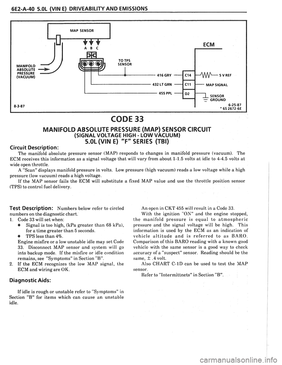
The manifold absolute pressure sensor (MAP) responds to changes in manifold pressure (vacuum). The
ECM receives this information as a signal voltage that will vary from about
1-1.5 volts at idle to 4-4.5 volts at
wide open throttle.
A "Scan" displays manifold pressure in volts. Low pressure (high vacuum) reads
a low voltage while a high
pressure (low vacuum) reads a high voltage.
If the MAP sensor fails the ECM will substitute
a fixed MAP value and use the throttle position sensor
(TPS) to control fuel delivery.
Test Description: Numbers below refer to circled
numbers on the diagnostic chart.
1. Code 33 will set when:
@ Signal is too high, (kPa greater than 68 kPa),
for a time greater than 5 seconds.
-S TPS less than 4%.
Engine misfire or a low unstable idle may set Code
33. Disconnect MAP sensor and system will go
into backup mode. If the misfire or idle condition
remains, see "Symptoms" in Section "B".
2. If the ECM recognizes the low MAP signal, the
ECM and wiring are OK.
Diagnostic Aids:
An open in CKT 455 will result in a Code 33.
With the ignition "ON" and the engine stopped,
the manifold pressure is equal to atmospheric
pressure and the signal voltage will be high.
This
information is used by the ECM as an indication of
vehicle altitude
and is referred to as BARO.
Comparison of this
BARO reading with a known good
vehicle with the same sensor is a good way to check
accuracy of a "suspect" sensor. Reading should he the
same,
& .4 volt.
Also
CHART C-lD can be used to test the MAP
sensor.
Refer to
"Intermittnets" in Section "B".
If idle is rough or unstable refer to "Symptoms" in
Section
"B" for items which can cause an unstable
idle.
Page 533 of 1825
6EZ-A-42 5.OL (VIN E) DRIVEABILITY AND EMISSIONS
CODE 34
MANIFOLD ABSOLUTE PRESSURE (MAP) SENSOR CIRCUIT
(SIGNAL VOLTAGE LOW - HIGH VACUUM)
5.OL (VIN E) ""F-SERlES (TBI)
Circuit Description:
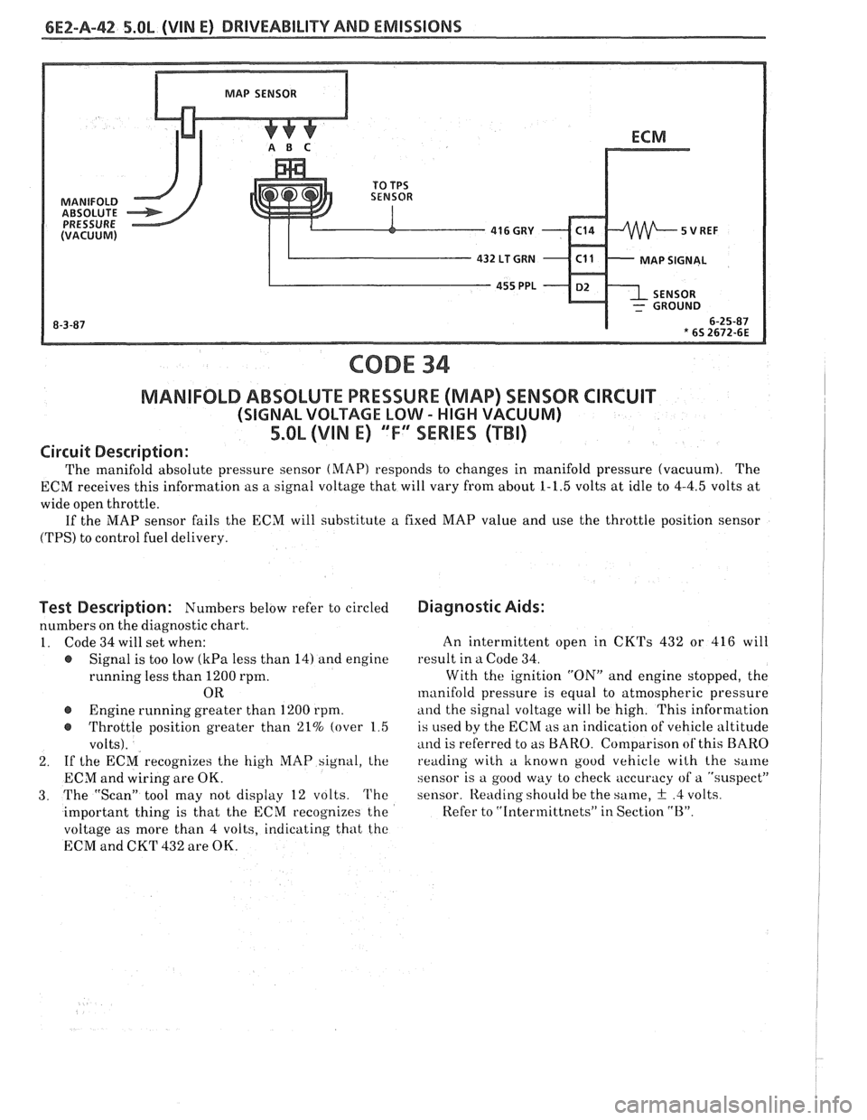
The manifold absolute pressure sensor (MAP) responds to changes in manifold pressure (vacuum). The
ECM receives this information as a signal voltage that will vary from about 1-1.5 volts at idle to 4-4.5 volts at
wide open throttle.
If the MAP sensor fails the ECM will substitute a fixed MAP value and use the throttle position sensor
(TPS) to control fuel delivery.
Test Description: Numbers below refer to circled
numbers on the diagnostic chart.
1. Code 34 will set when:
e Signal is too low (kPa less than 14) and engine
running less than 1200 rpm.
OR
@ Engine running greater than 1200 rpm.
e Throttle position greater than 21% (over 1 5
volts).
2. If
the ECM recognizes the high hIAP signal, the
ECM and wiring are OK.
3. The "Scan" tool may not display 12 volts. The
important thing is that the ECM recognizes the
voltage as more than 4 volts, indicating that tho
ECM and CKT 432 are OK.
Diagnostic Aids:
An intermittent open in CKTs 432 or 416 will
result in a Code 34.
With the ignition "ON" and engine stopped, the
manifold pressure is equal to atmospheric pressure
and the signal voltage will be high. This information
is
used by the ECM as an indication of vehicle altitude
and is referred to as BARO. Comparison of this BARO
reading with a known good vehicle wilh the same
sensor is a good way to check accuracy of a "suspect"
sensor.
Iteading shoulci be the same, + .4 volts.
Refer to "Intermittnets" in Section "B".
Page 537 of 1825
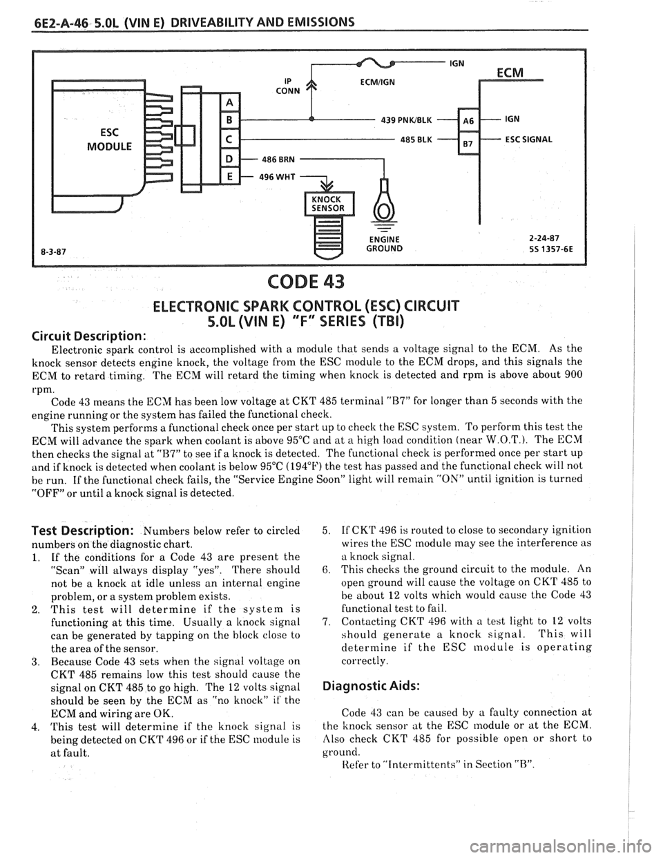
CODE 43
ELECTRONIC SPARK CONTROL (ESC) CIRCUIT
5.0L (VIN E) "F" SERIES (TBI)
Circuit Description:
Electronic spark control is accomplished with a module that sends a voltage signal to the ECM. As the
knock sensor detects engine knock, the voltage from the ESC module to the ECM drops, and this signals the
ECM to retard timing. The ECM will retard the timing when knock is detected and rpm is above about 900
rpm. Code 43 means the ECM has been low voltage at CKT 485 terminal
"B7" for longer than 5 seconds with the
engine running or the system has failed the functional check.
This system performs a functional check once per start up to check the ESC system. To perform this test the
ECM will advance the spark when coolant is above 95°C and at
a high load condition (near W.O.T.). The ECM
then checks the signal at
"B7" to see if a knock is detected. The functional check is performed once per start up
and if knock is detected when coolant is below 95°C (194°F) the test has passed and the functional check will not
be run. If the functional check fails, the "Service Engine Soon" light will
remain "ON" until ignition is turned
"OFF" or until a knock signal is detected.
Test Description: Numbers below refer to circled
numbers on the diagnostic chart.
1. If the conditions for a Code 43 are present the
"Scan" will always display "yes". There should
not be a knock at idle unless an internal engine
problem, or a system problem exists.
2. This test will determine if the system is
functioning at this time. Usually a
knock signal
can be generated by tapping on the block close to
the area of the sensor.
3. Because Code 43 sets when the signal voltage on
CKT 485 remains low this test should cause the
signal on CKT 485 to go high. The
12 volts signal
should be seen by the ECM as "no knock"
it' the
ECM and wiring are OK.
4.
This test will determine if the knock signal is
being detected on CKT 496 or if the ESC module is
at fault. 5.
If
CKT 496 is routed to close to secondary ignition
wires the ESC
module may see the interference as
a knock signal.
6. This checks the ground circuit to the module. An
open ground will cause the voltage on CKT 485 to
be about
12 volts which would cause the Code 43
functional test to fail.
7. Contacting
CKT 496 with a test light to
12 volts
should generate a knock signal.
This will
determine if the ESC nodule is operating
correctly.
Diagnostic Aids:
Code 43 can be caused by a faulty connection at
the knock sensor at the ESC
lnodule or at the ECM.
Also check CKT 485 for possible open or short to
ground.
Iiefer to "Intcrmittents" in Section "B".
Page 548 of 1825
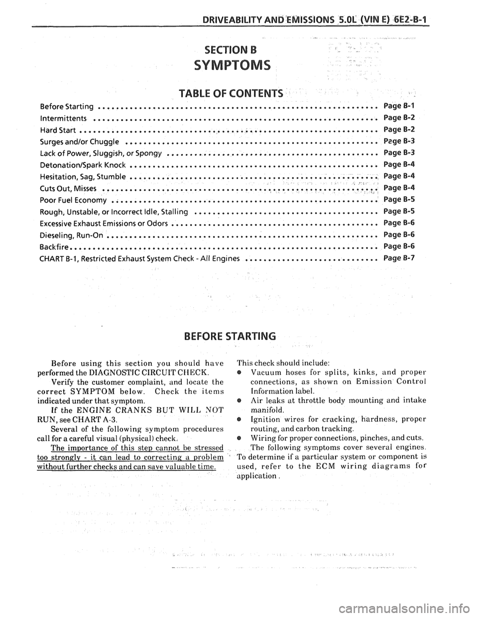
TABLE OF CONTENTS
............................................................. Before Starting Page B-1
lntermittents .............................................................. PageB-2
HardStart........,........................................................ PageB-2
...................... .................. Surges and/or Chuggle .... ........ ... Page B-3
.............................................. Lack of Power, Sluggish, or Spongy Page 8-3
DetonationISparkKnock ...................................................... PageB-4
...................................................... Hesitation,
Sag, Stumble Page B-4 8 .......................................................... Cuts Out, Misses ? .I Page 8-4
PoorFuelEconomy .......................................................... PageB-5
........................................ Rough, Unstable, or Incorrect Idle, Stalling Page
B-5
............................................. Excessive Exhaust Emissions or Odors Page
B-6
........................................................... Dieseling, Run-on Page B-6
Backfire......,..,.........,............................................... PageB-6
............................. CHART B-1, Restricted Exhaust System Check -All Engines Page B-7
BEFORE
STARTING
Before using this section you should have This check should include:
performed the DIAGNOSTIC CIRCUIT
CHECK. @ Vacuum hoses for splits, kinks, and proper
Verify the customer complaint, and locate the connections,
as shown on Emission Control
correct SYMPTOM below. Check the items Information label.
indicated under that symptom.
@ Air leaks at throttle body mounting and intake
If the ENGINE CRANKS BUT WILL NOT manifold.
RUN, see CHART
A-3. @ Ignition wires for cracking, hardness, proper
Several of the following symptom procedures routing,
and carbon tracking.
call for a careful visual (physical) check.
@ Wiring for proper connections, pinches, and cuts.
The importance of this step cannot be stressed The
following symptoms cover several engines.
too strongly
- it can lead to correcting a problem To
determine if a particular system or component is
without further checks and can save valuable time. used,
refer to the ECCM wiring diagrams for
application .
Page 549 of 1825
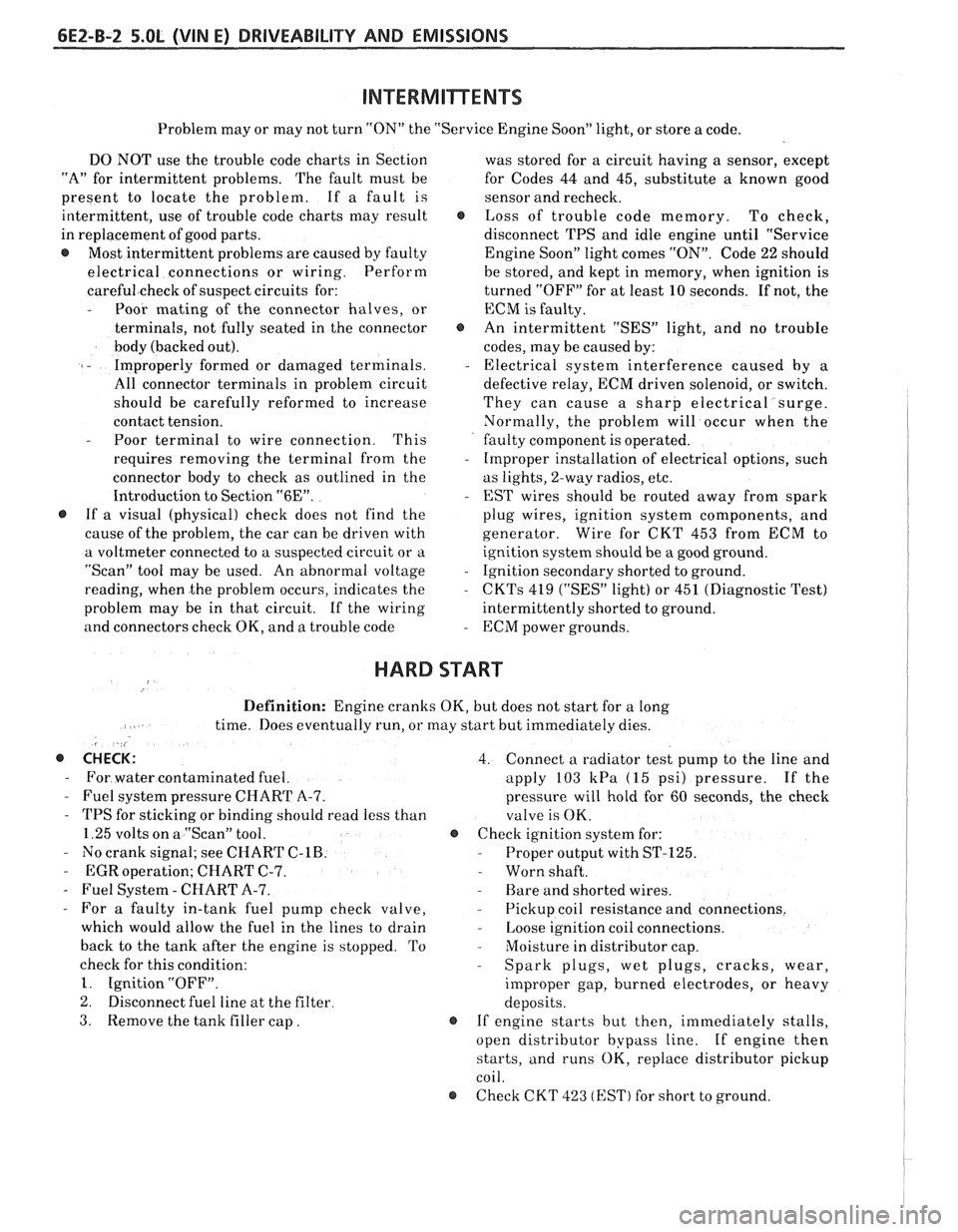
6EZ-B-2 5.OL (VIN E) DRIVEABILITY AND EMISSIONS
Problem may or may not turn "ON" the "Service Engine Soon" light, or store a code.
DO NOT use the trouble code charts in Section
"A" for intermittent problems. The fault must be
present to locate the problem. If a fault is
intermittent, use of trouble code charts may result
in replacement of good parts.
@ Most intermittent problems are caused by faulty
electrical connections or wiring. Perform
careful check of suspect circuits for:
- Poor mating of the connector halves, or
terminals, not fully seated in the connector
body (backed out).
I - Improperly formed or damaged terminals.
All connector terminals in problem circuit
should be carefully reformed to increase
contact tension.
- Poor terminal to wire connection. This
requires removing the terminal from the
connector body to check as outlined in the
Introduction to Section
"6E".
@ If a visual (physical) check does not find the
cause of the problem, the car can be driven with
a voltmeter connected to a suspected circuit or a
"Scan" tool may be used. An abnormal voltage
reading, when the problem occurs, indicates the
problem may be in that circuit. If the wiring
and connectors check OK, and a trouble code was
stored for a circuit having a sensor, except
for Codes 44 and 45, substitute a known good
sensor and recheck.
@ Loss of trouble code memory. To check,
disconnect TPS and idle engine until "Service
Engine Soon" light comes
"ON". Code 22 should
be stored, and kept in memory, when ignition is
turned "OFF" for at least 10 seconds. If not, the
ECM
is faulty.
@ An intermittent "SES" light, and no trouble
codes, may be caused by:
- Electrical system interference caused by a
defective relay, ECM driven solenoid, or switch.
They can cause a sharp electrical surge.
Normally, the problem will occur when the
faulty component is operated.
- Improper installation of electrical options, such
as lights, 2-way radios, etc.
- EST wires should be routed away from spark
plug wires, ignition system components, and
generator. Wire for CKT 453 from ECM to
ignition system should be a good ground.
- Ignition secondary shorted to ground.
- CKTs 419 ("SES" light) or 451 (Diagnostic Test)
intermittently shorted to ground.
- ECM power grounds.
HARD START
Definition: Engine cranks OK, but does not start for a long
time. Does eventually run, or may start but immediately dies.
, <
@ CHECK: 4. Connect a radiator test pump to the line and
- For water contaminated fuel. apply 103 kPa (15 psi) pressure. If the
- Fuel system pressure CHART A-7. pressure will hold for 60 seconds, the check
- TPS for sticking or binding should read less than
valve is OK.
1.25 volts on a "Scan" tool. @ Check ignition system for:
- No crank signal; see CHART C-1B. - Proper output with ST-125.
- EGR operation; CHART C-7. - Worn shaft.
- Fuel System - CHART A-7. - Rare and shorted wires.
- For a faulty in-tank fuel pump check valve, - Pickup coil resistance and connections.
which would allow the fuel in the lines to drain
- Loose ignition coil connections.
back to the tank after the engine is stopped. To
- Moisture in distributor cap.
check for this condition:
- Spark plugs, wet plugs, cracks, wear,
1. Ignition "OFF".
improper gap, burned electrodes, or heavy
2. Disconnect fuel line at the filter
deposits.
3. Remove the tank filler cap. @ If engine starts but then, immediately stalls,
open distributor bypass line. If engine then
starts, and runs OK, replace distributor pickup
coil.
@ Check CKT 423 (EST) for short to ground.
Page 555 of 1825
6EZ-C-1 5.OL (VIN E) DRIVEABILITY AND EMISSIONS
Section C provides information on the following:
@ General description of components and systems.
@ On-vehicle service.
@ Part names and group numbers.
@ Diagnostic charts. These include a functional check of the system as well as diagnosis of any problem
found in the functional check.
For locations of components, wiring diagrams, and ECM Terminal End View, refer to the front on the A Section
of the engine being diagnosed.
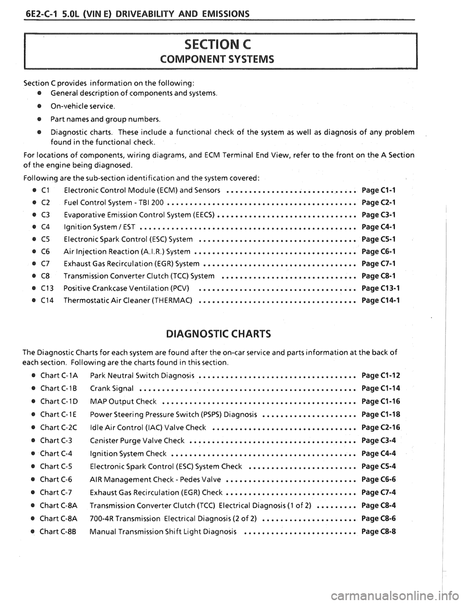
Following are the sub-section identification and the system covered:
@ C1 Electronic Control Module (ECM) and Sensors ............................. Page C1-1
@ C2 Fuel Control System - TBI 200 .......................................... Page C2-1
Evaporative Emission Control System (EECS) ...............................
Ignition System 1 EST ................................................
Electronic Spark Control (ESC) System ...................................
Air Injection Reaction (A.I.R.) System ....................................
Exhaust Gas Recirculation (EGR) System ..................................
Transmission Converter Clutch (TCC) System ..............................
Positive Crankcase Ventilation (PCV) ...................................
Thermostatic Air Cleaner (THERMAC) ...................................
BIAGNOSIIC CHARTS
Page C3-1
Page C4-1
Page C5-1
Page C6-1
Page C7-1
Page C8-1
Page C13-1
Page C14-1
The Diagnostic Charts for each system are found after the on-car service and parts information at the back of
each section. Following are the charts found in this section.
@ Chart C-1A Park Neutral Switch Diagnosis ................................... Page C1-12
@ Chart C-1B Crank Signal ................................................ Page C1-14
@ Chart C-1 D MAP Output Check ........................................ Page C1-16 I
..................... @ Chart C-1 E Power Steering Pressure Switch (PSPS) Diagnosis Page C1-18 1
................................ @ Chart C-2C Idle Air Control (IAC) Valve Check Page C2-16 !
..................................... @ Chart C-3 Canister Purge Valve Check Page C3-4 I
@ Chart C-4 Ignition System Check ......................................... Page C4-4
........................ @ Chart C-5 Electronic Spark Control (ESC) System Check Page C5-4
- ............................. @ Chart C-6 AIR Management Check Pedes Valve Page C6-6
............................. Chart C-7 Exhaust Gas Recirculation (EGR) Check Page C7-4
@ Chart C-8A Transmission Converter Clutch (TCC) Electrical Diagnosis (1 of 2) ......... Page C8-4 I
@ Chart C-8A 700-4R Transmission Electrical Diagnosis (2 of 2) ..................... Page C8-6 I
......................... @ Chart C-8B Manual Transmission Shift Light Diagnosis Page C8-8