1988 PONTIAC FIERO wiring
[x] Cancel search: wiringPage 172 of 1825
STEERING WHEELS AND COLUMNS 385-21
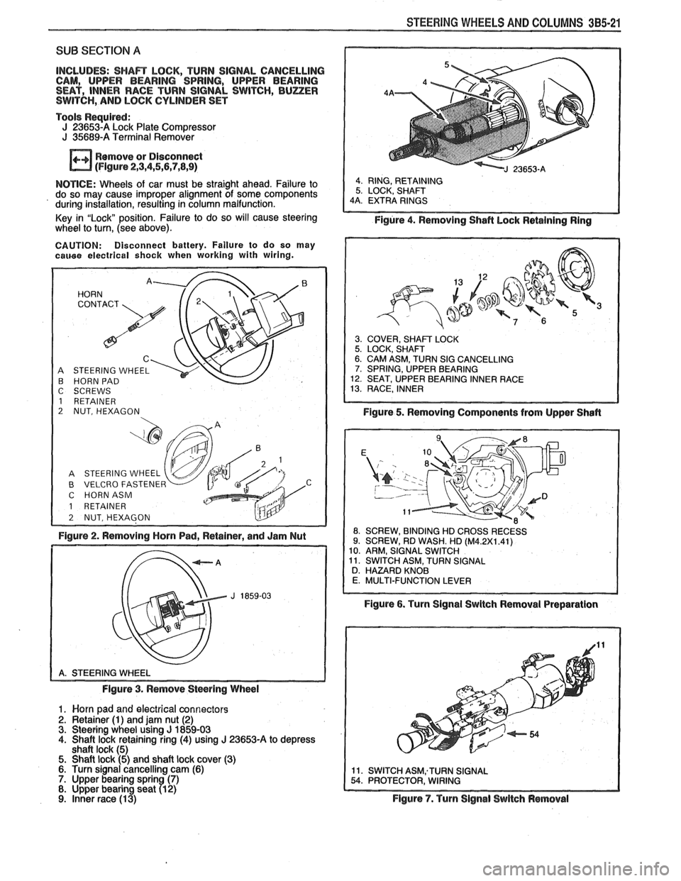
SUB SECTION A
INCLUDES: SHAR LOCK, TURN SIGNAL CANCELLING
CAM, UPPER BEARING SPRING, UPPER BEARING
SEAT, INNER RACE TURN SIGNAL SWITCH,
BUZER SWITCH, AND LOCK CYLINDER SET
Tools
Requird: J 236534 Lock Plate Compressor J 35689-A Terminal Remover
Remove or Disconnect
(Flgure 2,3,4,5,5,7,8,9)
NOTICE: Wheels of car must be straight ahead. Failure to
do so may cause improper alignment of some components
' during installation, resulting in column malfunction.
Key in "Lock" position. Failure to do so will cause steering
wheel
to turn, (see above).
CAUTION: Disconnect battery. Failure to do so may cauee electrical shock when working with wiring.
A STEERING WHEEL B HORN PAD
C SCREWS
1 RETAINER
2 NUT, HEXAGON
B VELCRO FASTENER C HORNASM
1 RETAINER
Figure 2. Removing Horn Pad, Retainer, and Jam Nut
Figure 3. Remove
Stwring Wheel
1. Worn pad and electrical connectors 2. Retainer (1) and jam nut (2) 3. Steering wheel using J 1859-03 4. Shaft lock retaining ring (4) using J 23653-A to depress
shaft lock (5) 5. Shaft lock (5) and shaft lock cover (3) 6. Turn signal cancelling cam (6) 7. Upper bearing sprin (7) 8. Upper bearing seat 71 2)
9. inner race (1 3)
Figure 4. Removing Shafl hock Retaining Ring
3. COVER, SHAFT LOCK 5. LOCK, SHAFT 6. CAM ASM, TURN SIG CANCELLING 7. SPRING, UPPER BEARING 12. SEAT, UPPER BEARING INNER RACE 13. RACE, INNER
Figure 5. Removing Components from Upper Shafl
ROSSRECESS
Figure 6. Turn Signal Swltch Removal Preparation
Figure
7. Turn Signal Switch Removal
Page 173 of 1825
385-22 STEERING WHEELS AND COLUMNS
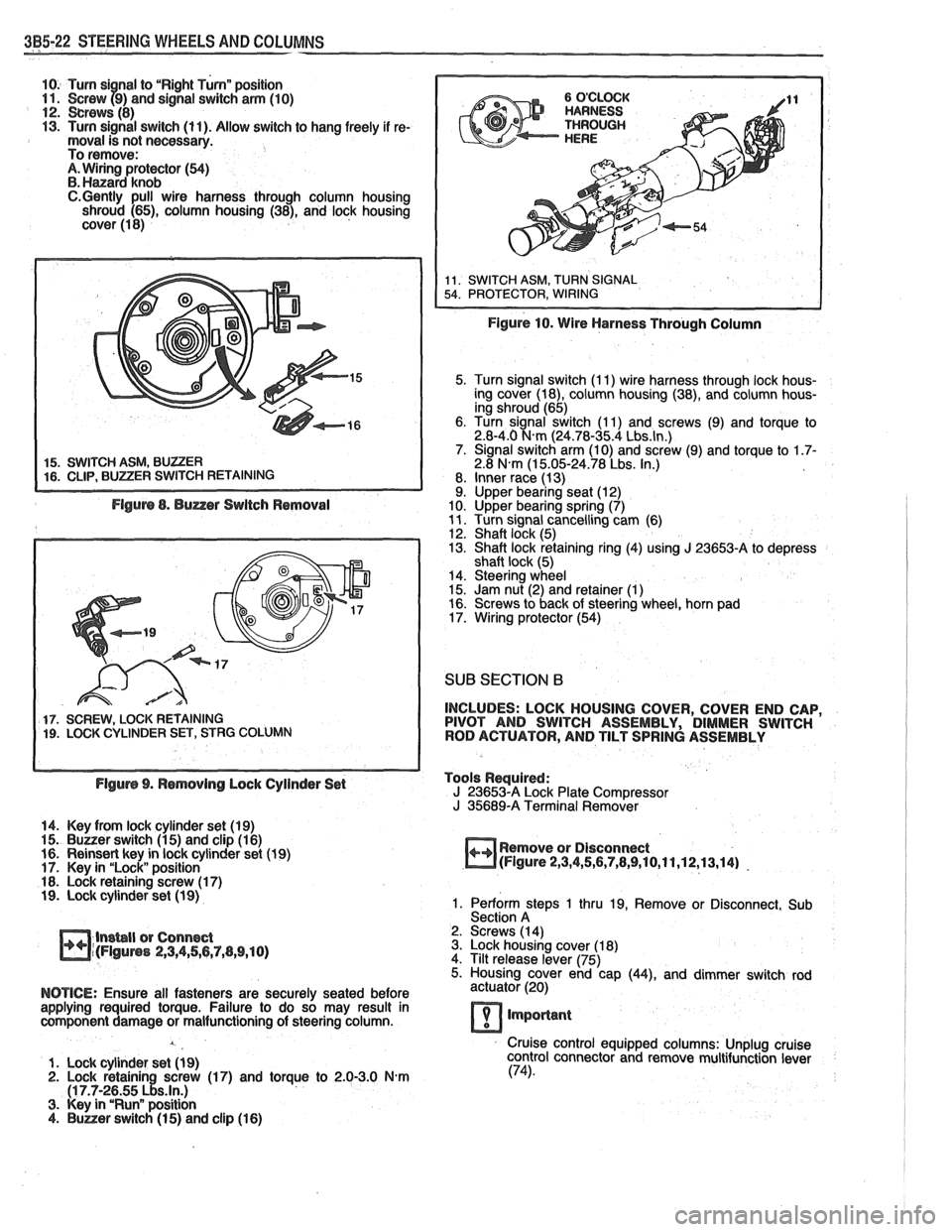
10. Turn si nal to "Right Turnn position 11. Screw f9) and signal switch arm (10) 12. crews (8) 13. Turn signal switch (11). Allow switch to hang freely if re- moval is not necessary.
To remove:
A. Wiring protector (54) B. Hanard knob C.Gently pull wire harness through column housing
shroud (65), column housing (38), and lock housing
cover (1 8)
5. Turn signal switch (I 1) wire harness through lock hous-
ing cover (18), column housing (38), and column hous-
ing shroud (65)
6. Turn signal switch (1 1) and screws (9) and torque to
2.8-4.0
N.m (24.78-35.4 Lbs.ln.) 7. Signal switch arm (10) and screw (9) and torque to 1.7- 2.8 N.m (1 5.05-24.78 Lbs. In.)
8. Inner race (13)
9. Upper bearing seat (12)
10. Upper bearing spring (7)
11. Turn signal cancelling cam (6)
12. Shaft lock (5)
13. Shaft lock retaining ring (4) using J 23653-A to depress
shaft lock (5)
14. Steering wheel
15. Jam nut (2) and retainer
(1) 16. Screws to back of steering wheel, horn pad
17. Wiring protector (54)
SUB SECTION 6
17. SCREW, LOCK RETAINING INCLUDES:
LOCK HOUSING COVER, COVER END CAP, 19. LOCK CYLINDER SET, STRG COLUMN PIVOT
AND SWITCH ASSEMBLY, DIMMER SWITCH
ROD ACTUATOR, AND TILT SPRING ASSEMBLY
Flgurs 9. Rsmovlng Lock Cylinder Set Tools
Required:
J 23653-A Lock Plate Compressor
J 35689-A Terminal Remover
14. Key from lock cylinder set (19)
15.
Buuer switch (1 5) and clip (1 6)
16. Reinsert key in lock cylinder set (1 9) Remove
or Disconnect
17. Key in "Lock" position
m(Flgure 2,3,4,5,6,7,8,9,10,11,12,13,14) -
18. Lock retaining screw (1 7) 19. Lock cylinder set (1 9) 1. Perform steps 1 thru 19, Remove or Disconnect, Sub
Section A
lnsbll or Connect 2.
Screws (14)
m~(FIguns 2,3,4,56,7,(1,9,10) 3. Lock housing cover (1 8)
4. Tilt release lever (75)
5. Housing cover end cap
(44), and dimmer switch rod
NOTICE: Ensure all fasteners are securely seated before actuator (20)
applying required torque. Failure to do so may result in
component damage or malfunctioning of steering column.
lmporlant
Cruise control equipped columns: Unplug cruise
1. Lock cylinder set
(1 9) control
connector and remove multifunction lever 2. Lock retainin screw (17) and torque to 2.0-3.0 N-m (74).
(1 7.7-2~55 ~!s.ln.) 3. Key in "Runn position 4. Buner switch (1 5) and clip (1 6)
Page 180 of 1825
STEERING WHEELS AND COLUMNS 3B5-29
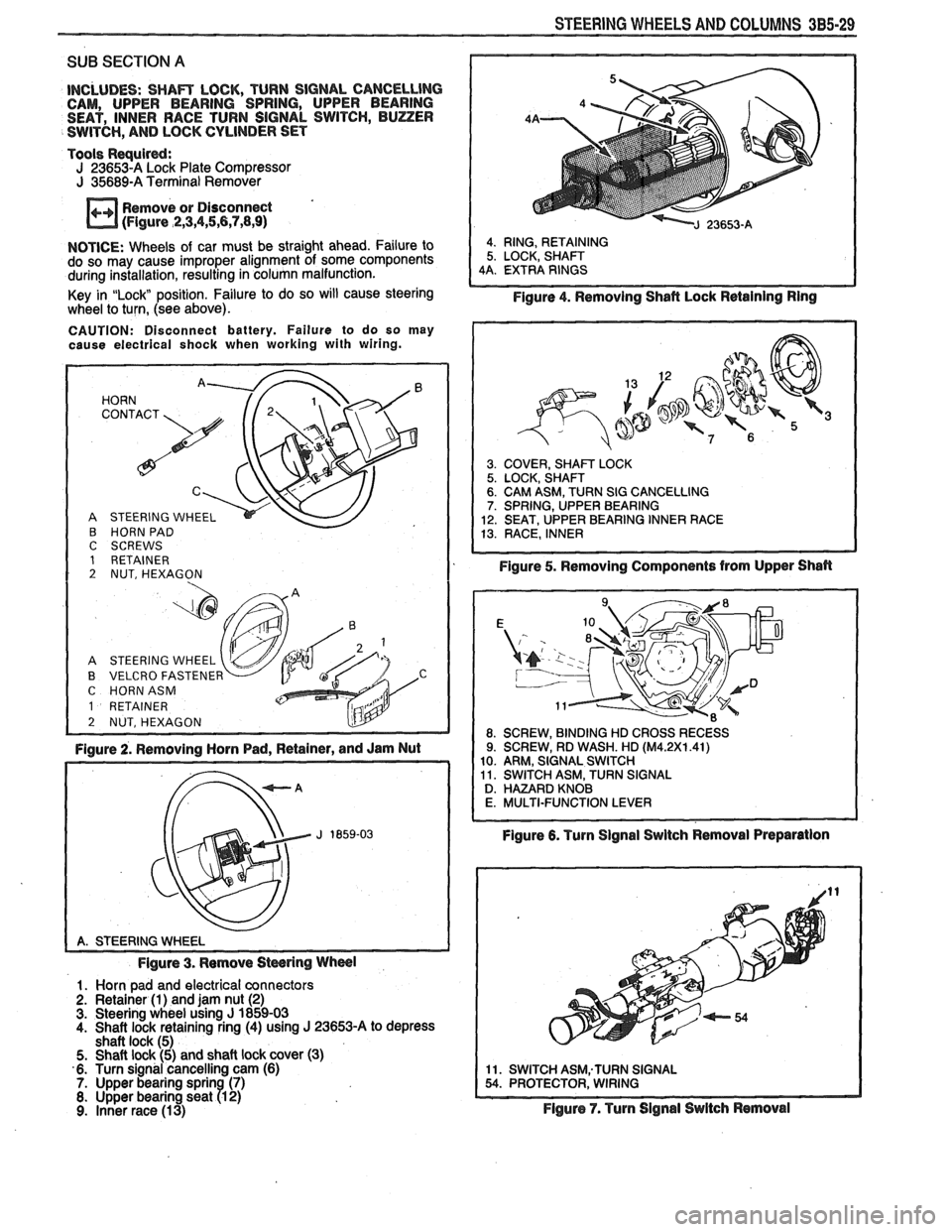
SUB SECTION A
INCLUDES: SHAm LOCK, TURN SIGNAL CANCELLlNG CAM, UPPER BEARING SPRING, UPPER BEARING
SEAT, INNER RACE TURN SIGNAL SWITCH, BUZZER
SWITCH,
AND LOCK CYLINDER SET
Tools
Requird: J 23653-A Lock Plate Compressor J 35689-A Terminal Remover
Remove or Disconnect
(Figure
,2,3,4,5,6,7,8,9)
NOTICE: Wheels of car must be straight ahead. Failure to
do so may cause improper alignment of some components
during installation, resulting in column malfunction.
Key in
"Lock position. Failure to do so will cause steering
wheel to turn, (see above).
CAUTION: Disconnect battery. Failure to do so may
cause electrical shock when working with wiring.
HORN '. 72' CONTACT
A STEERING WHEEL
B HORN PAD C SCREWS 1 RETAINER 2 NUT, HEXAGON
A STEERING WHEEL
B VELCRO FASTENER C HORNASM
1 RETAINER
2 NUT, HEXAGON L!lY -
Figure 2. Removing Horn Pad, Retainer, and Jam Nut
Figure 3. Remove
Stwring Wheel
1. Horn pad and electrical connectors
2. Retainer (1) and jam nut (2) 3. Steering wheel using J 1859-03
4. Shaft lock retaining ring (4) using J 23653-A to depress
shaft lock (5)
5. Shaft lock (5) and shaft lock cover (3)
6. Turn signal cancelling cam (6)
7. Upper bearing sprin (7) 8. Upper bearing seat R 2) 9. Inner race (13)
4. RING, RETAINING
5. LOCK, SHAFT
4A. EXTRA RINGS
Figure 4. Removing Shafl Lock Retaining Ring
3. COVER, SHAm LOCK 5. LOCK, SHAFT 6. CAM ASM, TURN SIG CANCELLING 7. SPRING, UPPER BEARING
12. SEAT, UPPER BEARING INNER RACE
13. RACE, INNER
Figure 5. Removing Components from Upper Shan
Figure 6. Turn Signal Swltch Removal Preparation
11. SWITCH ASM;TURN SIGNAL 54. PROTECTOR, WIRING
Flgure 7. Turn Signal Switch Removal
Page 181 of 1825
385-30 STEERING WHEELS AND COLUMNS
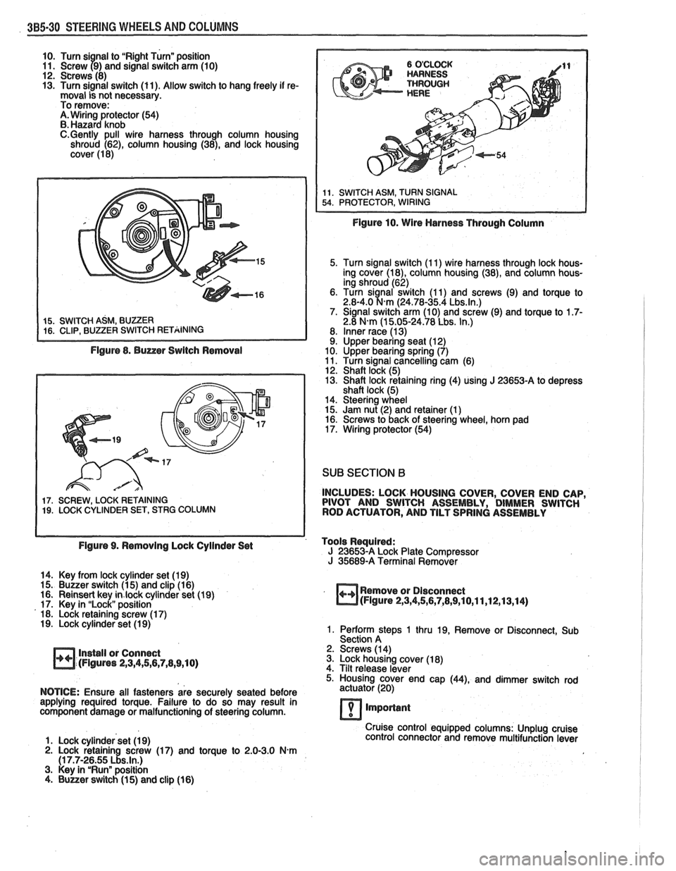
10. Turn si nal to "Right Turn" position
11. Screw 79) and signal switch arm (10)
12. Screws (8)
13. Turn signal switch (11). Allow switch to hang freely if re-
moval is not necessary.
To remove:
A. Wiring protector (54)
B. Hazard knob
C.Gently pull wire harness through column housing
shroud (62), column housing (38), and lock housing
cover (1 8)
Figure 8. Buzzer Switch Removal
17. SCREW, LOCK RETAINING 19. LOCK CYLINDER SET, STRG COLUMN
Figure 10. Wire Harness Through Column
5. Turn signal switch (1 1) wire harness through lock hous-
ing cover
(la), column housing (38), and column hous-
ing shroud (62)
6. Turn
sianal switch (1 1) and screws (9) and torque to 2.8-4.0 %km (24.78-35.4 Lbs.ln.) 7. Signal switch arm (10) and screw (9) and torque to 1.7- 2.8 N-m (1 5.05-24.78 Lbs. In.)
8. Inner race (1 3) 9. Upper bearing seat (1 2)
10. Upper bearing spring (7)
11. Turn signal cancelling cam (6)
12. Shaft lock (5)
13. Shaft lock retaining ring (4) using
J 23653-A to depress
shaft lock (5)
14. Steering wheel
15. Jam nut (2) and retainer (1
) 16. Screws to back of steering wheel, horn pad
17. Wiring protector (54)
SUB SECTION B
INCLUDES: LOCK HOUSING COVER, COVER END CAP,
PIVOT AND SWITCH ASSEMBLY, DIMMER SWITCH
ROD ACTUATOR, AND TILT SPRING ASSEMBLY
Figure 9. Removing Lock Cyilnder Set Tools
Rwuired: J 23653-A Lock
Plate Compressor J 35689-A Terminal Remover
14. Key from lock cylinder set (19)
15. Buzzer switch (1 5) and clip (1 6)
16. Reinsert key
in.lock cylinder set (19)
17. Key in "Lock" position
18. Lock retaining screw (1 7)
19. Lock cylinder set (1 9)
Install or Connect
(Figures
2,3,4,5,6,7,8,9,10)
Remove or Dlsconnect (Figure 2,3,4,5,6,7,8,9,10,11,12,13,14)
1. Perform steps 1 thru 19, Remove or Disconnect, Sub
Section A
2. Screws (1 4)
3. Lock housing cover (1 8)
4. Tilt release lever
5. Housing cover end cap
(44), and dimmer switch rod
NOTICE: Ensure all fasteners are securely seated before actuator
(20)
applying required torque. Failure to do so may result in
component damage or malfunctioning of steering column.
7 important
Cruise control equipped columns: Unplug cruise
1. Lock cylinder set (1 9) control
connector and remove multifunction lever
2. Lock retaining screw (17) and torque to 2.0-3.0 N.m (1 7.7-26.55 Lbs.ln.) 3. Key in "Run" position
4. Buuer switch (1 5) and clip (16)
Page 307 of 1825
2. Console. Refer to INSTRUMENT PANEL, GAGES
AND CONSOLE (SEC.
8C).
3. Wiring from switch.
4. Cable and casing from control assembly. * Use a lh-inch box end wrench to free casing
from control assembly.
5. Two bolts and control assembly from floor pan.
Install or Connect (Figure 12)
1. Two bolts and control assembly to floor pan.
Two bolts to 10
N.m (7 Ibs. ft.).
2. Cable and casing to control assembly.
3. Wiring to switch.
4. Console. Refer to INSTRUMENT PANEL, GAGES
AND CONSOLE (SEC.
8C).
5. Carpet finish molding.
@ Parking brake. See Section 566 or 5C3.
PARKING BRAKE CABLES
Parking Brake Front Cable
Remove or Disconnect (Figure 12)
@ Raise vehicle. See Section OA.
1. Adjusting nut from equalizer.
2. Spring retainer clip from bracket. * Lower vehicle. See Section OA.
3. Upper console cover and lower console rear screws.
@ Lift rear of lower console for access to cable retainer
at hand lever.
4. Cable retainer pin, cable retainer and cable.
Install or Connect (Figure 12)
1. Cable, cable retainer and cable retainer pin.
2. Lower console rear screws and upper console cover.
Raise vehicle. See Section OA.
3. Spring retainer clip to bracket.
4. Adjusting nut to equalizer.
Lower vehicle. See Section OA.
Adjust
Parking brake. See Section 586 or 5C3.
Parking Brake Rear Cable (Drum Brakes)
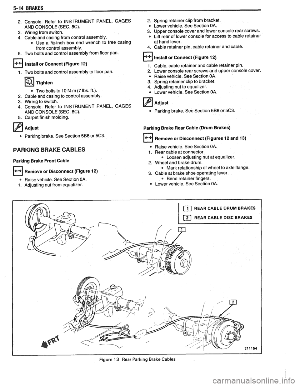
Remove or Disconnect (Figures 12 and
13)
* Raise vehicle. See Section OA.
1. Rear cable at connector.
Loosen adjusting nut at equalizer.
2. Wheel and brake drum. * Mark relationship of wheel to axle flange.
3. Cable at brake shoe operating lever.
* Bend retainer fingers.
Lower vehicle. See Section OA.
Figure
13 Rear Parking Brake Cables
Page 310 of 1825
BRAKES 5-17
maintaining proper wheel balance, brake drums should be
checked for balance. Brake drums may be checked for
balance on most off-the-car balancers.
COMBINATION VALVE
Testing Combination Valve Electrical Circuit
When removing the electrical wire connector from the
pressure differential switch, squeeze the
eliptical shaped
plastic locking ring and pull up. This will move the locking
tangs away from the switch. Pliers can be used to help
remove the connector.
1. Disconnect wire from switch terminal and use a
jumper to connect wire to a good ground.
2. Turn ignition key to "ON." The warning lamp should
light. If lamp does not light, bulb is burned out or
electrical circuit is faulty. Replace bulb or repair elec-
trical circuit as necessary.
3. When warning lamp lights, turn off ignition switch.
Disconnect jumper and connect wire to switch termi-
nal.
Testing Combination Valve Warning Lamp Switch
1. Attach a bleeder hose to a rear brake bleed screw and
immerse the other end of the hose in a container
partially filled with clean brake fluid. Be sure master
cylinder reservoirs are full.
2. Turn ignition switch to "ON." Open bleeder screw
while an assistant applies moderate pressure to the
brake pedal. Warning lamp should light. Close
bleeder screw before assistant releases brake pedal.
Apply brake pedal with moderate-to-heavy pressure.
Lamp should go out.
3. Attach the bleeder hose to a front brake bleeder
screw and repeat steps
1 and 2. Warning lamp action
should be the same as in step
2. Turn off ignition
switch.
4. If warning lamp does not light during steps 2 and 3,
but does light when a jumper is connected to ground,
the warning lamp switch portion of the combination
valve is faulty. Do not disassemble the combination
valve.
If any portion of the combination valve is faulty,
it must be replaced with a new combination valve.
Combination Valve Replacement
Remove or Disconnect (Figure
16)
r The combination valve is not repairable and must be
serviced as a complete assembly.
1. Hydraulic pipes at combination valve.
Plug pipes to prevent loss of fluid and entrance
of dirt.
2. Wiring harness from valve switch terminal.
3. Nut attaching valve to power booster.
4. Combination valve.
@ Install or Connect (Figure 16)
NOTICE: See "Notice" on page 5-1.
1. Combination valve.
2. Nut attaching valve to power booster.
Tighten
* Nut to 24 N.m (18 Ibs. ft.).
3. Wiring harness to valve switch terminal.
4. Hydraulic pipes at combination valve. * Bleed brakes. See "Bleeding Brake Hydraulic Sys-
tem" in this section.
CAUTION: Do not move the car until a firm brake
pedal is obtained. Air in the brake system can
cause loss of brakes.
POWER BRAKE VACUUM HOSE FILTER
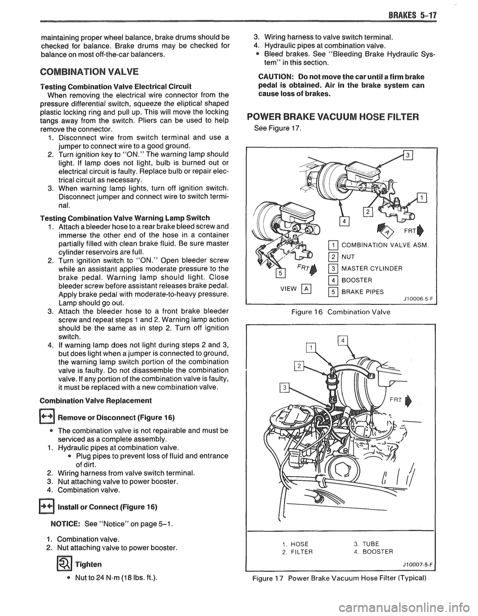
See Figure 17.
COMBINATION VALVE ASM.
MASTER CYLINDER BRAKE PIPES
Figure 16 Combination Valve
2 FILTER 4. BOOSTER
Figure 17 Power Brake Vacuum Hose Filter (Typical)
Page 347 of 1825
6-2 ENGINE GENERAL INFORMATION
6E3 - Fuel Injection (Ported) This section has information
on all exhaust
system parts, such as tailpipes, mufflers, and the
SECTION 6F - EXHAUST SYSTEM catalytic converter.
GENERAL INFORMAflION
CLEANLINESS AND CARE
An automobile engine is a combination of many
machined, honed, polished and lapped surfaces with
tolerances that are measured in the ten-thousandths of
an inch. When any internal engine parts are serviced,
care and cleanliness are important. A liberal coating of
engine oil should be applied to friction areas during
assembly, to protect and lubricate the surfaces on
initial operation. Throughout this section, it should be
understood that proper cleaning and protection of
machined surfaces and friction areas is part of the
repair procedure. This is considered standard shop
practice, even if not specifically stated. PREVENTING
DAMAGE AND IN
CONTRIBUTING TO RELIABLE ENGINE
PERFORMANCE.
When raising or supporting the engine for any
reason, do not use a jack under the oil pan. Due to the
small clearance between the oil pan and the oil pump
screen, jacking against the oil pan may cause it to be
bent against the pump screen resulting in a damaged
oil pick-up unit.
When working on the engine, remember that the
12-volt electrical system is capable of causing short
circuits. When performing any work where electrical terminals could possibly be grounded, the ground cable
of the battery should be disconnected at the battery.
Any time the carburetor or air cleaner is
train components are removed removed, the intake opening should be covered. This for service, they should be in order' will protect against entrance of foreign be installed in the same locations, and with the same material, which could follow the intake passage into mating surfaces, as when removed
the cylinder and cause extensive damage when the -
Battery cables should be disconnected before any engin; is started.
major work is performed on the engine. Failure to IN THE MECHANICAL PROCEDURES
disconnect cables may result in damage to wire harness DESCRIBED IN THIS SECTION, GENERALLY
or other electrical parts. NO
REFERENCES WILL BE MADE TO THE
REMOVAL OF OPTIONAL EQUIPMENT SUCH
ENGINE SERVICE AS POWER STEERING PUMP, AIR
CONDITIONING COMPRESSOR, ETC.
THE FOLLOWING INFORMATION ON SHOULD IT BECOME NECESSARY TO
ENGINE SERVICE SHOULD BE NOTED REMOVE ANY SUCH ITEM TO
PERFORM
CAREFULLY, AS IT IS IMPORTANT IN OTHER SERVICE, REFER TO THE
APPROPRIATE SECTION OF THIS SERVICE
MANUAL FOR SPECIFIC INFORMATION.
ENGINE PERFORMANCE DIAGNOSIS
INTRODUCTION interchangeably for so long, it was necessary to decide
on the most common usage and then define them. If the
Engine Performance procedures are definition is not understood, and the exact Symptom is
guides that will lead to the most probable causes of not used, the Diagnostic procedure will not work. engine performance complaints. They cover the
components of the fuel, ignition, and mechanical It
is important to keep two facts in mind:
systems that could cause a particular
complaint, and 1. The procedures are written to diagnose problems
then outline repairs in a logical sequence. on cars
that have
"run well at one time" and
that time and wear have created the condition.
It is important to determine if the
"Service ~~~i~~ soon- light is "ON,~' or has come for 2. All possible causes cannot be covered,
a short interval while driving. If the
"Service Engine particularly with regard to emission controls. If
Soon" light has come "ON," the Computer doing the work prescribed does not correct the
Command Control System or DECS should be complaint, then either the wrong Symptom was
checked for stored
"Trouble Codes" (See Diagnostic used, or a more detailed analysis will have to be
Circuit Check, Section 6E, for the engine you are made.
working on) which may indicate the cause for the All of the Symptoms can be caused by worn out
performance
complaint.Each Symptom is defined, and or defective parts such as Spark Plugs, Ignition
it is important that the correct one be selected, based Wiring, etc. If time and/or mileage indicate that
on the complaints reported or found. The definition of parts should be replaced, it is recommended that
each symptom is included with the symptom. it
be done.
The words used may not be what you are used to Refer to:
in all cases, but because these terms have been used
@ Section 6E - Driveability and Emissions
Page 376 of 1825
2.8 LITER V-6 6A2-25
Fitting
1. Select rings comparable in size to the piston being
used.
2. Slip
the compression ring in the cylinder bore;
then press the ring down into the cylinder bore
about 6mm above ring travel. Be sure ring is
square with cylinder wall.
3. Measure the space or gap between the ends of the
ring with a feeler gage (Figure
6A2-33).
4. If
the gap between the ends of the ring is below
specifications, remove the ring and try another
for fit.
5. Fit each compression ring to the cylinder in
which it is going to be used.
6. If the pistons have not been cleaned and inspected
as previously outlined, do so.
7. Slip the outer surface of the top and second
compression ring into the respective piston ring
groove and roll the ring entirely around the
groove (Figure
6A2-34). If binding occurs at any
point, the cause should be determined. If there is
a ring groove, remove by dressing with a fine cut
file. If the binding is caused by a distorted ring,
check a new ring.
Installation
1. Install oil ring spacer in groove being sure ends
are butted and not overlapped.
2. Hold
spacer ends butted and install lower steel oil
ring rail.
3. Install upper
steel oil ring rail with gap staggered.
4. Flex
the oil ring assembly to make sure ring is
free. If binding occurs, the cause should be
detemined. If caused by ring groove, remove by
dressing groove with a fine cut file. If binding is
caused by a distorted ring, check a new ring.
5. Install second compression ring. Stagger gap
from other rings.
6. Install top compression ring with gap properly
located.
ENGINE ASSEMBLY
Removal
Disconnect battery.
Remove air cleaner.
Remove hood. Drain radiator.
Remove lower radiator hose.
Remove upper fan shroud.
Remove upper radiator hose and coolant
recovery hose.
Remove transmission cooler lines. Remove radiator.
Remove fan assembly.
Remove heater hoses.
Disconnect carburetor linkage, includes cruise
control detent cable.
Remove vacuum brake booster line.
Remove distributor cap and lay wiring aside.
Disconnect necessary wires and hoses.
Remove power steering pump and lay aside. Raise
vehicle.
Remove exhaust pipes at exhaust manifold.
Remove dust cover.
Remove converter bolts.
Disconnect starter wires.
Remove bell housing bolts.
Remove motor mount through bolts.
Disconnect fuel lines at fuel pump.
Lower vehicle. Support transmission.
Remove
A.I.R./Converter pipes bracket.
Remove engine, include removing wire from
bracket at rear left of engine.
Installation
Position engine assembly in vehicle.
Attach motor mount to engine brackets and
lower engine in place.
Remove engine lifting device.
Remove transmission floor jack.
Raise vehicle on hoist.
Install mount "through" bolts. Torque to
specifications.
Install bell housing bolts. Torque to
specifications.
On vehicles with automatic transmission, install
converter to flywheel attaching bolts. Torque to
specifications.
Install flywheel splash shield of conveter housing
cover as applicable. Torque attaching bolts to
specifications.
Install starter wires.
Connect fuel lines.
Connect exhaust pipe at manifold.
Lower vehicle on hoist.
Reinstall power steering pump, if so equipped.
Connect necessary wires and hoses.
Install radiator and fan shroud and reconnect
radiator and heater hoses.
Fill cooling system.
Fill crankcase with oil. See owner's manual for
specifications.
Install air cleaner.
Install hood.
Connect battery cables.
NOTICE: To avoid possible arcing of battery,
connect positive battery cable first.
22. Start engine, check for leaks and check timing.
CRANKSHAFT
The crankshaft can be removed while the engine
is dissasembled for overhaul, as previously outlined or
without complete disassembly.
Removal
1. With the engine removed from the vehicle,
remove the clutch assembly (if equipped) and
flywheel. Mount engine in stand and clamp
securely.