1988 PONTIAC FIERO wiring
[x] Cancel search: wiringPage 71 of 1825
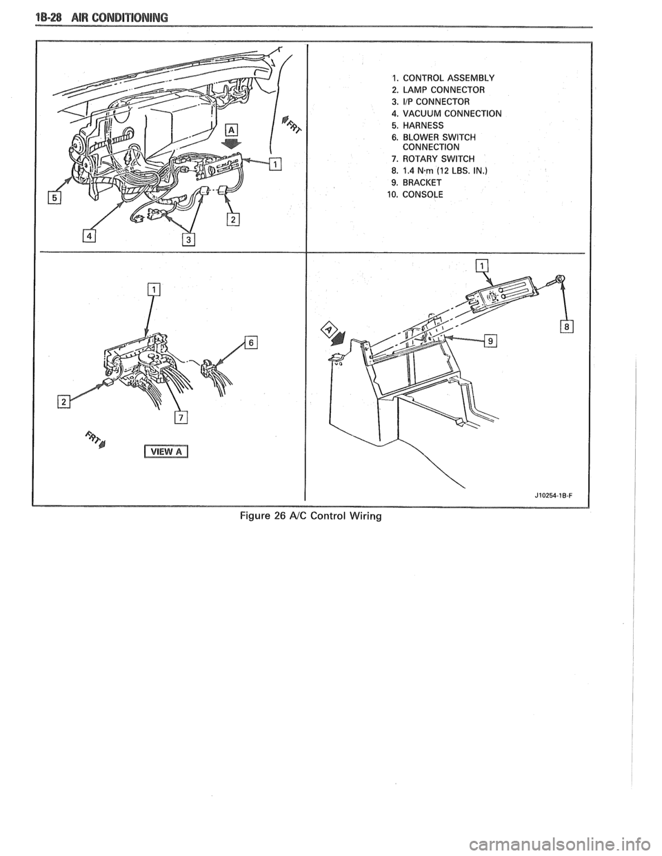
"1-28 AIR CONDITIORIBNG
Figure 26 AtC Control Wiring
Page 72 of 1825
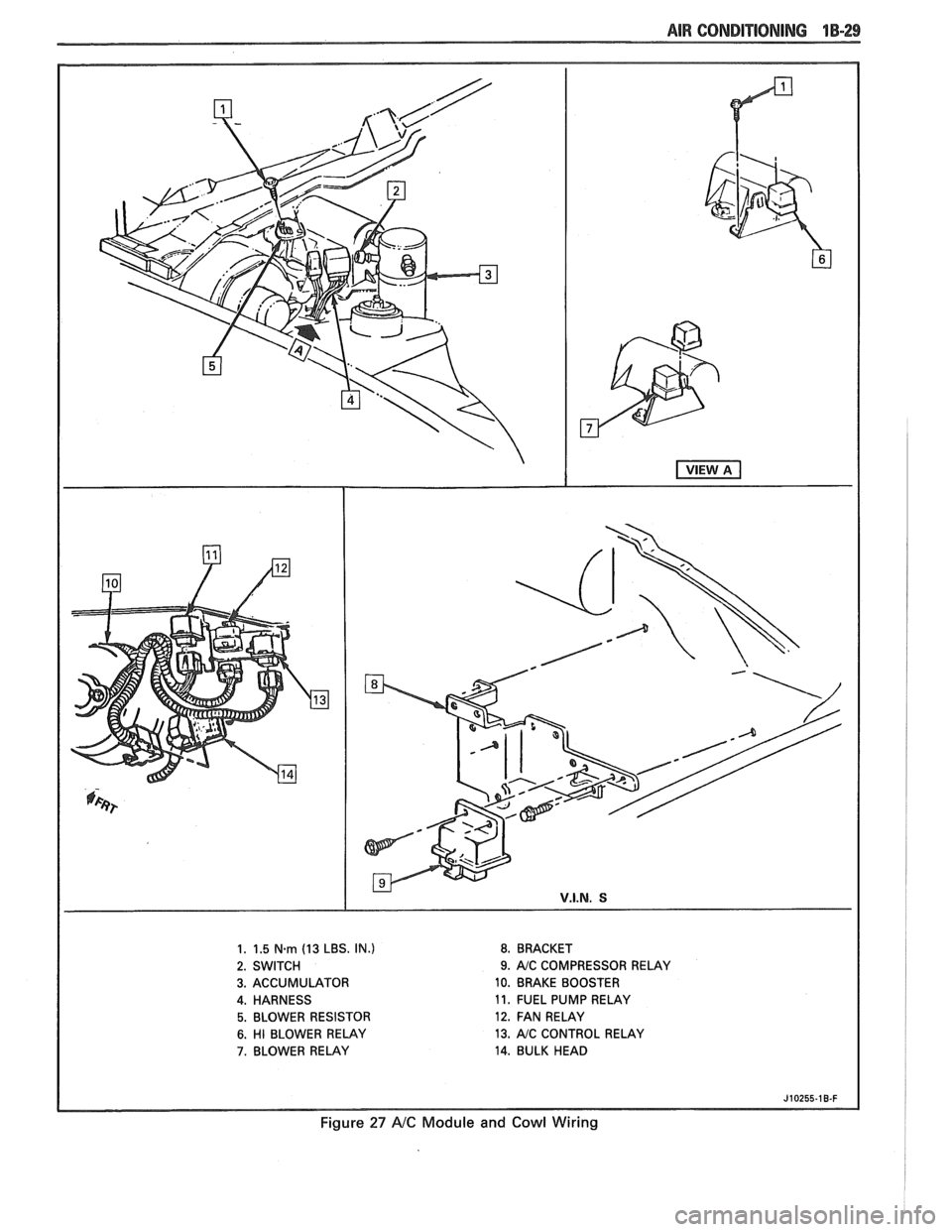
AIR CONDITIONING 1B-29
1. 1.5 N.m (13 LBS. IN.) 8. BRACKET
2. SWITCH
9. AJC COMPRESSOR RELAY
3. ACCUMULATOR 10. BRAKE BOOSTER
4. HARNESS 11.
FUEL PUMP RELAY
5. BLOWER RESISTOR 12. FAN RELAY
6. HI BLOWER RELAY 13. AJC CONTROL
RELAY
7. BLOWER RELAY 14. BULK HEAD
J10255-18-F
Figure 27 A/C Module and Cowl Wiring
Page 132 of 1825
STEERING, SUSPENSION, TIRES AND WHEELS DIAGNOSIS 3-7
e To determine if turn signal switch is inoperative,
substitute new turn signal switch into circuit and
operate switch by hand.
If the car's lights operate
normally, turn signal switch is inoperative.
Front Or Rear Turn Signal Lights Not Flashing
Inspect
s Burned-out or damaged turn signal bulb
e High resistance conection to ground at bulb
socket
s Loose chassis-to-column connector. Disconnect
column-to-chassis connector and connect new
turn signal switch into system and operate switch
by hand.
A. If turn signal lights are now on and flashing,
turn signal switch is inoperative.
B. If car lights do not operate, refer to Section
8A
for electrical diagnosis.
Turn Indicator Panel Lights
Inspect
Burned out bulbs or opens, grounds in the wiring
harness from the front turn signal bulb socket to the
indicator lights. Refer to Section
8A for electrical
diagnosis.
Stop Light Mot On When Turn Indicated
Inspect
s Loose column-to-chassis connection
e Disconnect the column-to-chassis connector and
connect the new turn signal switch into the
system and operate the switch by hand.
A. If the brake lights work when the switch is
in the turn position, the turn signal switch
is inoperative.
B. If the brake lights do not work, refer to Section
8A for electrical diagnosis.
Turn Signal Lights Flash Very Slowly
e Loose chassis-to-column connection
a Disconnect the column-to-chassis connector and
connect a new turn signal switch into the system
and operate the switch by hand.
A. If the lights flash at a normal rate, the turn
signal switch is inoperative.
B. If the Lights still flash very slowly, refer to
Section
8A for electrical diagnosis.
Hazard Signal Lights Will Not Flash - Turn
Signal Functions Normally
~"SPBC~
a Blown fuse
Inoperative hazard warning flasher
e Loose chassis-to-column connection
s Disconnect the column-to-chassis connector and
connect a new turn signal switch into the system,
then press in the hazard warning button and
watch the hazard warning lights.
A. If the lights now work normally, the turn
signal switch is inoperative.
B. If the lights do not flash, check the wiring
harness. Refer to Section
8A for electrical
diagnosis.
IGNITION SWITCH
Electrical System Will Not Function
Damaged ign~rion switch
e Ignition switch not adjusted properly
e Loose connector at the ignition switch
Switch Will Not Turn
Inspect
Damaged ignition switch
Switch Cannot Be Set Correctly
Inspect
Switch actuator rod deformed
e Sector to rack engaged in wrong tooth
KEY REMINDER
Figs. 1 through 11 ,
Weminder Continues To Operate With Key Out,
But Stops When Driver's Door Is Closed
e Chips, foreign material in lock cylinder bore
Sticky lock cylinder actuator tip
Damaged or broken reminder switch
Reminder Does Not Sound With Key Fully
Inserted In Lock Cylinder And The Driver's Door
Open
Inspect
1. Power not available to reminder. Refer to Sec-
tion
8A for electrical diagnosis.
2. Open in chassis wiring. Check by separating
chassis-to-column connector. Connect terminals
"E" and "F" female contacts on the chassis
connector (a bent paper clip will work). If the
reminder sounds, repair chassis wiring. If the
reminder does not sound, go to Step
A.
A. Connect a continuity meter (light) to the
male
"E" and "F" column connector
contacts. Push the key all the way into the
lock cylinder. If the light is on when the key
Page 133 of 1825
3-8 STEERING. SUSPENSION. TIRES AND WHEELS DIAGNOSIS
is in, and off when the key is out, the
function is normal. If the light is not on, the
fault is in the column. Go to Step B.
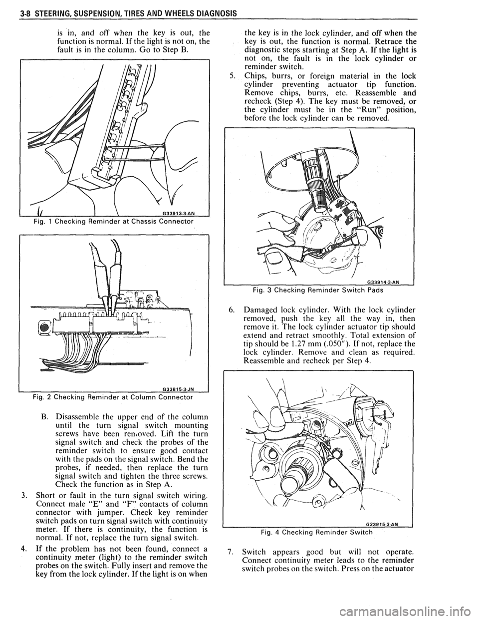
Fig. 1 Checking Reminder at Chassis Connector
Fig.
2 Checking Reminder at Column Connector
B. Disassemble the upper end of the column
until the turn
signal switch mounting
screws have been
removed. Lift the turn
signal switch and check the probes of the
reminder switch to ensure good contact
with the pads on the signal switch. Bend the
probes, if needed, then replace the turn
signal switch and tighten the three screws.
Check the function as in Step
A.
3. Short or fault in the turn signal switch wiring.
Connect male
"E" and "F" contacts of column
connector with jumper. Check key reminder
switch pads on turn signal switch with continuity
meter. If there is continuity, the function is
normal. If not, replace the turn signal switch. the
key is in the lock cylinder, and off when the
key is out, the function is normal. Retrace the
diagnostic steps starting at Step
A. If the light is
not on, the fault is in the lock cylinder or
reminder switch.
Chips, burrs, or foreign material in the lock
cylinder preventing actuator tip function.
Remove chips, burrs, etc. Reassemble and
recheck (Step 4). The key must be removed, or
the cylinder must be in the "Run" position,
before the lock cylinder can be removed.
Fig. 3 Checking Reminder Switch Pads
6. Damaged lock cylinder. With the lock cylinder
removed, push the key all the way in, then
remove it. The lock cylinder actuator tip should
extend and retract smoothly. Total extension of
tip should be
1.27 mm (.05OU). If not, replace the
lock cylinder. Remove and clean as required.
Reassemble
and recheck per Step 4.
Fig. 4 Checking Reminder Switch
4.. If the problem has not been found, connect a 7. switch appears good but will not operate, continuity meter (light) to the reminder switch
Connect continuity meter leads to the reminder
probes on the switch. Fully insert and remove the
switch probes on the switch. Press on the actuator
key from the lock cylinder. If the light is on when
Page 160 of 1825
STEERING WHEELS AND COLUMNS 385-9
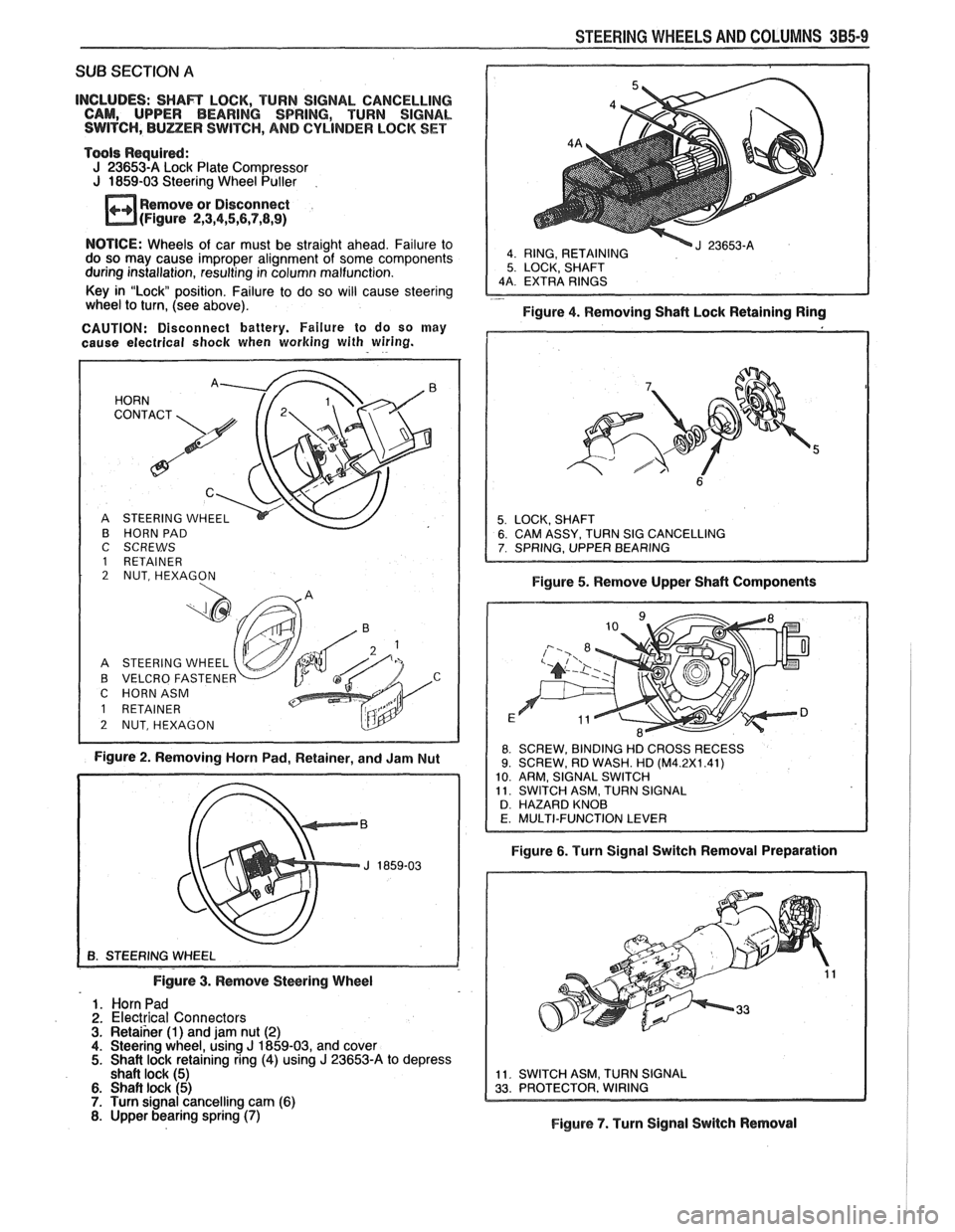
SUB SECTION A
INCLUDES: SHAR LOCK, TURN SIGNAL CANCELLING
CAM, UPPER BEARING SPRING, TURN SIGNAL
SWITCH,
BULZER SWITCH, AND CYLINDER LOCK SET
Tools Required:
J 23653-A Lock Plate Compressor
J 1859-03 Steering Wheel Puller
Remove or Disconnect
(Figure
2,3,4,5,6,7,8,9)
4 RING, RETAINING 5 LOCK, SHAFT
NOTICE: Wheels of car must be straight ahead. Failure to
do so may cause improper alignment of some components
during installation, resulting in column malfunction.
Key in "Lock position. Failure to do so will cause steering
- wheel to turn, (see above).
Figure 4. Removing Shaft Lock Retaining Ring
CAUTION: Disconnect battery. Failure to do so may
cause electrical
shock when working with wiring.
B HORN PAD
C SCREWS
1 RETAINER 2 NUT, HEXAGON
A STEERING WHEEL
B VELCRO FASTENE
C HORNASM
Figure 2. Removing Horn Pad, Retainer, and Jam Nut Figure
5. Remove Upper Shaft Components
8 SCREW,
BINDING HD CROSS RECESS 9. SCREW, RD WASH. HD (M4.2X1.41)
10 ARM, SIGNAL SWITCH
11 SWITCH ASM, TURN SIGNAL
D HAZARD KNOB
Figure 6. Turn Signal Switch Removal Preparation
Figure
3. Remove Steering Wheel
1. Horn Pad
2. Electrical Connectors 3. Retaiher (1) and jam nut (2) 4. Steering wheel, using J 1859-03, and cover 5. Shait lock retaining ring (4) using J 23653-A to depress
shaft lock (5)
6. Shaft lock (5) 7. Turn signal cancelling cam (6) 8. Upper bearing spring (7) Figure 7. Turn Signal Switch Removal
Page 165 of 1825
SAGINAW STEERING GEAR DIVISION
GENERAL MOTORS CORPORATION
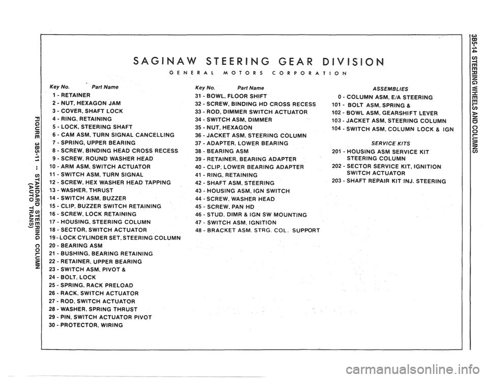
Key No. Part Name
1 - RETAINER
2
- NUT, HEXAGON JAM
3
- COVER, SHAFT LOCK
4
- RING, RETAINING
5
- LOCK, STEERING SHAFT
6
- CAM ASM, TURN SIGNAL CANCELLING
7
- SPRING, UPPER BEARING
8
- SCREW, BINDING HEAD CROSS RECESS
9 - SCREW, ROUND WASHER HEAD
10
- ARM ASM, SWlTCH ACTUATOR
11
- SWITCH ASM, TURN SIGNAL
12
- SCREW, HEX WASHER HEAD TAPPING
13
- WASHER, THRUST
14
- SWITCH ASM, BUZZER
15
- CLIP, BUZZER SWITCH RETAINING
16
- SCREW, LOCK RETAINING
17
- HOUSING, STEERING COLUMN
18
- SECTOR, SWITCH ACTUATOR
19 -LOCK CYLINDER SET, STEERING COLUMN
20
- BEARING ASM
21
- BUSHING, BEARING RETAINING
22
- RETAINER, UPPER BEARING
23
- SWITCH ASM, PIVOT &
24 - BOLT, LOCK
25
- SPRING, RACK PRELOAD
26
- RACK. SWlTCH ACTUATOR
27 - ROD, SWITCH ACTUATOR
28
- WASHER. SPRING THRUST
29 - PIN, SWITCH ACTUATOR PIVOT
30
- PROTECTOR, WIRING
Key No. Part Name ASSEMBLIES
31 - BOWL, FLOOR SHIFT
0 - COLUMN ASM, E/A STEERING
32
- SCREW, BINDING HD CROSS RECESS
101 - BOLT ASM, SPRING &
33 - ROD, DIMMER SWITCH ACTUATOR
102 - BOWL ASM. GEARSHIFT LEVER
34
- SWITCH ASM, DIMMER
103 - JACKET ASM, STEERING COLUMN
35
- NUT, HEXAGON 104 - SWITCH ASM, COLUMN LOCK & IGN
36 - JACKET ASM, STEERING COLUMN
37
- ADAPTER, LOWER BEARING SERVlCE KITS
38 - BEARING ASM 201 - HOUSING ASM SERVICE KIT
39
- RETAINER, BEARING ADAPTER STEERING
COLUMN
40
- CLIP. LOWER BEARING ADAPTER 202 - SECTOR SERVICE
KIT, IGNITION
41
- RING. RETAINING SWITCH
ACTUATOR
42
- SHAFT ASM, STEERING 203 - SHAFT
REPAIR KIT INJ. STEERING
43
- HOUSING ASM, IGN SWITCH
44
- SCREW. WSHER HEAD
45
- SCREW, PAN HD
46
- STUD, DlMR & IGN SW MOUNTING
47
- SWITCH ASM, IGNITION
48 - BRACKET ASM. STRG. COL. SUPPORT
Page 166 of 1825
SUB SECTION A
INCLUDES: SHAFT LOCK, TURN SIGNAL CANCELLING
CAM, UPPER BEARING SPRING, SHAFT ASSEMBLY,
AND LOWER BEARING ASSEMBLY
Tools Required:
J 23653-A Lock Plate Compressor J 1859-03 Steering Wheel Puller
Remove or Disconnect
(Figures
2,3,4,5,6)
NOTICE: Wheels of car must be straight ahead. Failure to
do so may cause improper alignment of some components
during installation, resulting in
colunin malfunction.
Key in "Lock" position. Failure to do so
wi!l cause steering
wheel to turn, (see above).
CAUTION: Disconnect battery. Failure to do so may
cause electrical shock when working with wiring.
HORN
C
STEERING WHEEL
HORN PAD
I
C SCREWS
1 RETAINER
2 NUT, HEXAGON
A STEERING WHEEL
B VELCRO
FASTENEF v C HORNASM
1 RETAINER
2 NUTSHEXAGON
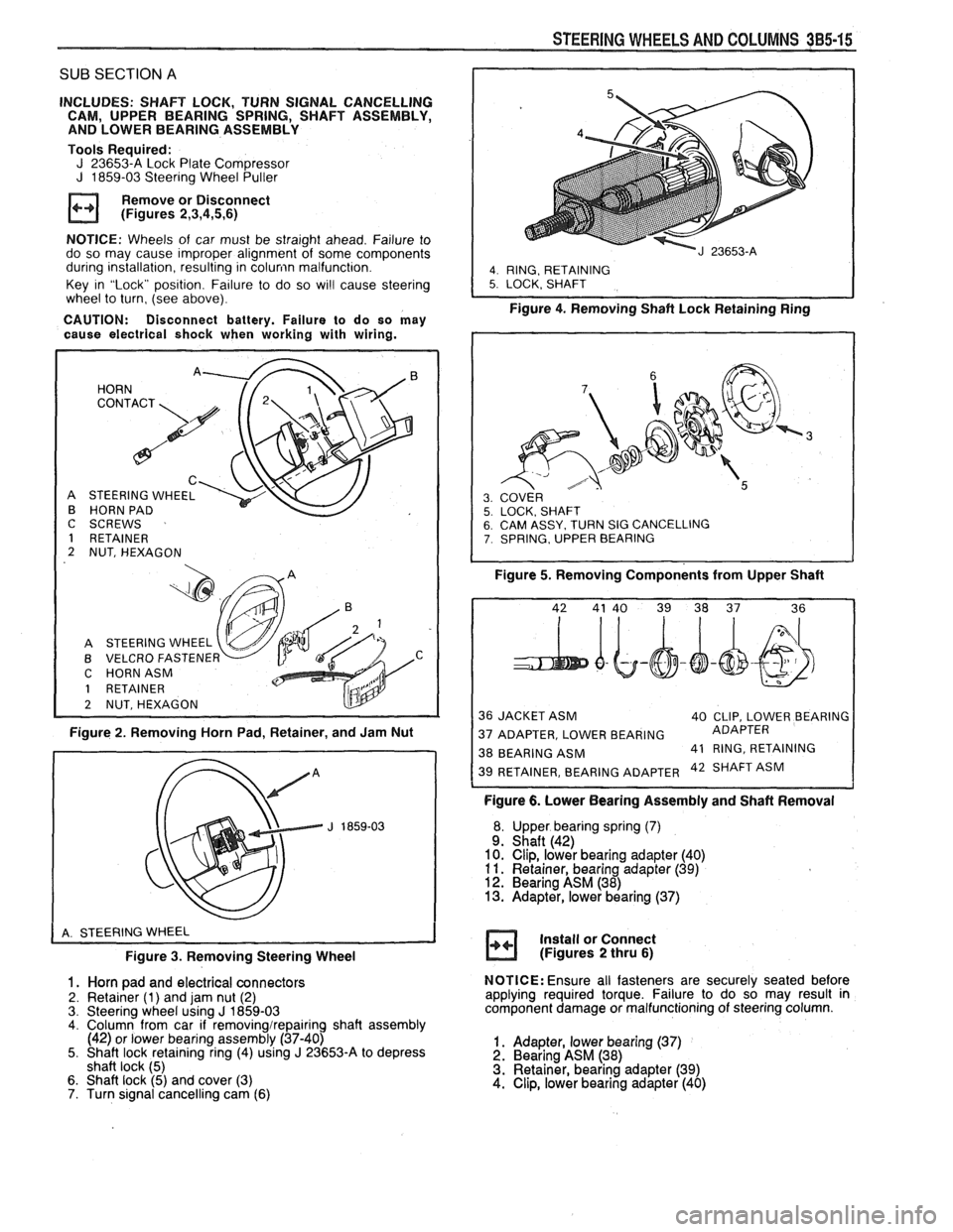
Figure 2. Removing Horn Pad, Retainer, and Jam Nut
Figure
3. Removing Steering Wheel
1. Horn pad and electrical connectors
2. Retainer (1) and jam nut (2)
3. Steering wheel using J 1859-03 4. Column from car if removingirepairing shaft assembly
(42) or lower bearing assembly (37-40)
5. Shaft lock retaining ring (4) using
J 23653-A to depress
shaft lock (5)
6. Shaft lock (5) and cover (3)
7. Turn signal cancelling cam (6)
STEERING WHEELS AND COLUMNS 385-15
I
4. RING, RETAINING 5. LOCK. SHAFT
Figure 4. Removing Shaft Lock Retainingain;
SY. TURN SIG CANCELLING , UPPER BEARING
Figure 5. Removing Components from Upper Shaft
36 JACKET ASM
40 CLIP, LOWER BEARING
37 ADAPTER, LOWER BEARING ADAPTER
38 BEARING
ASM 41
RING, RETAINING 42 SHAFT ASM
Figure 6. Lower Bearing Assembly and Shaft Removal
Upper bearing spring
(7) Shaft (42)
Clip, lower bearing adapter (40)
Retainer, bearing adapter
(39) Bearing ASM (38) Adapter, lower bearing (37)
Install or Connect
(Figures
2 thru 6)
NOTICE: Ensure all fasteners are securely seated before
applying required torque. Failure to do so may result in
component damage or malfunctioning of steering column.
1. Adapter, lower bearing (37) 2. Bearing ASM (38)
3. Retainer, bearing adapter (39)
4. Clip, lower bearing adapter (40)
Page 171 of 1825
GENERAL MOTORS CORPORATION
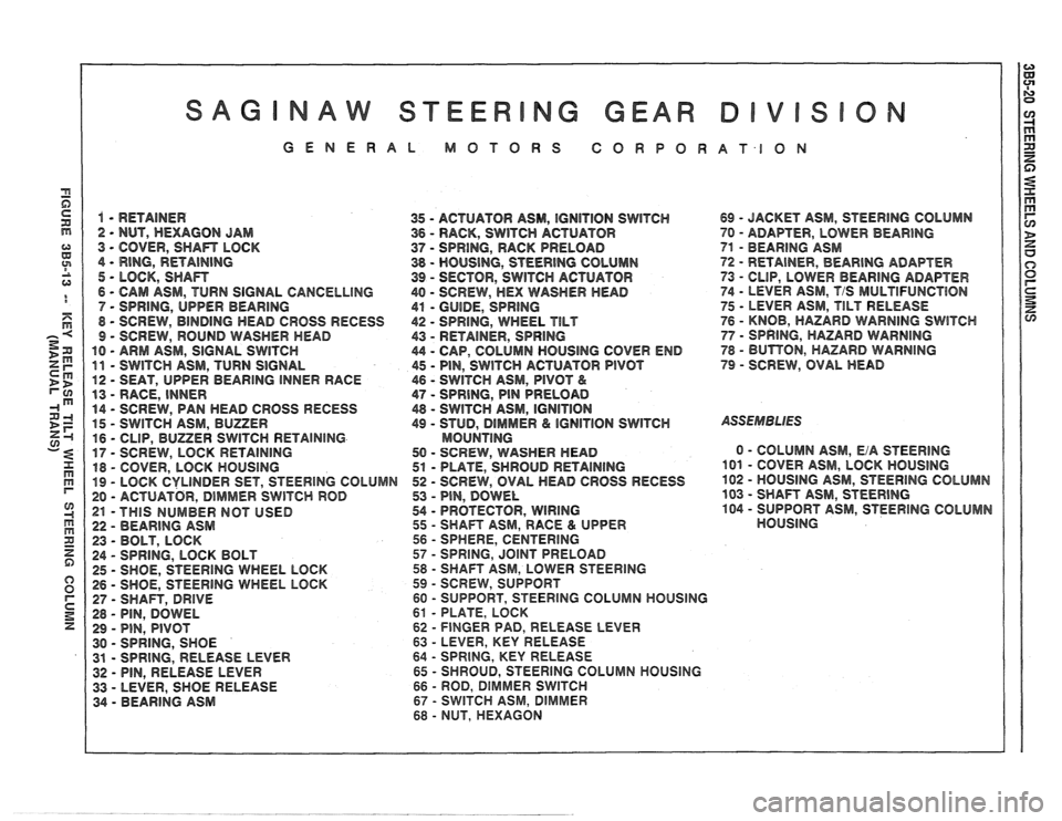
1 - RETAINER
35 - ACTUATOR ASM, IGNITION SWITCH 69 - JACKET ASM, STEERING COLUMN
2 - NUT, HEXAGON JAM
36 - RACK, SWITCH ACTUATOR 70 - ADAF"TER, LOWER BEARING
3 - COVER, SHAn LOCK 37 - SPRING, RACK PRELOAD 71 - BEARING ASM
4
- RING, RETAINING 38 - HOUSING, STEERING COLUMN 72 - RETAINER, BEAR1NG ADAPTER
5 - LOCK, SHAn 39 - SECTOR, SWITCH ACTUATOR
73 - CLIP, LOWER BEARING ADAPTER
6
- CAM ASM, TURN SIGNAL CANCELLING 40 - SCREW, HEX WASHER HEAD 74 - LEVER ASM, T/S MULTlFUNCTBON
7 - SPRING, UPPER
BEARING
41 - GUIDE, SPRING 75 - LEVER ASM, TILT RELEASE
8
- SCREW, BINDING HEAD CROSS RECESS 42 - SPRING, WHEEL TILT 76 - KNOB, HAZARD WARNING SWlTCH
9 - SCREW, ROUND WASHER MEAD
43 - RETAINER, SPRING 77 - SPRING, HAZARD WARNING
10 - ARM ASM, SIGNAL SWITCH 44 - CAP, COLUMN HOUSING COVER END 78 - BUTBON, HAZARD WARNING
11 - SWITCH
ASM, TURN SIGNAL 45 - PIN, SWITCH ACTUATOR PIVOT 79 - SCREW, OVAL HEAD
12
- SEAT, UPPER BEARING INNER RACE 46 - SWITCH ASM, PIVOT &
13 - RACE, INNER 47 - SPRING, PIN PRELOAD
14
- SCREW, PAN HEAD CROSS RECESS 48 - SWITCH ASM, IGNITION
15 - SWITCH
ASM, BUZZER 49 - STUD, DlMMER & IGNITION SWITCH ASSEMBLIES
16 - CLIP, BUZZER SWITCH RETAINING MOUNTlNG
17 - SCREW,
LOCK RETAINING 50 - SCREW, WASHER HEAD 0 - COLUMN
ASM, EiA STEERING
18
- COVER, LOCK HOUSING 51 - PLATE, SHROUD RETAINING 101 - COVER ASM, LOCK HOUSING
19 - LOCK CYLINDER SET, STEERING COLUMN 52 - SCREW,
OVAL HEAD GROSS RECESS 102 - HOUSING
ASM, STEERlNG COLUMN
20
- ACTUATOR, DIMMER SWITCH ROD 53 - PIN, DOWEL 103 - SHAFT
ASM, STEERING
21 -THIS NUMBER NOT USED 54 - PROTECTOR, WIRING
104 - SUPPORT
ASM, STEERING COLUMN
22
- BEARING ASM 55 - SHAFT
ASM, RACE & UPPER HOUSING
23
- BOLT, LOCK 56 - SPHERE,
CENTERING
24
- SPRING, LOCK BOLT 57 - SPRING, JOINT PRELOAD
25
- SHOE, STEERING WHEEL LOCK 58 - SHAFT ASM, LOWER STEERING
26 - SHOE, STEERING WHEEL LOCK 59 - SCREW,
SUPPORT
27
- SHAFT, DRIVE 60 - SUPPORT, STEERlNG COLUMN HOUSING
28
- PIN, DOWEL 61 - PLATE,
LOCK
29
- PIN, PIVOT 62 - FINGER PAD, RELEASE LEVER
30
- SPRING, SHOE 63 - LEVER, KEY RELEASE
31
- SPRING, RELEASE LEVER 64 - SPRING,
KEY RELEASE
32 - PIN, RELEASE LEVER 65 - SHROUD, STEERING COLUMN HOUSING
33
- LEVER, SHOE RELEASE 66 - ROD, DIMMER SWlTCH
34 - BEARING ASM 67 - SWITCH ASM, DlMrVlER
68 - NUT,
HEXAGON