1988 PONTIAC FIERO wiring
[x] Cancel search: wiringPage 681 of 1825
6E3-A-28 2.8L (VIN S) DRIVEABILITY AND EMISSIONS
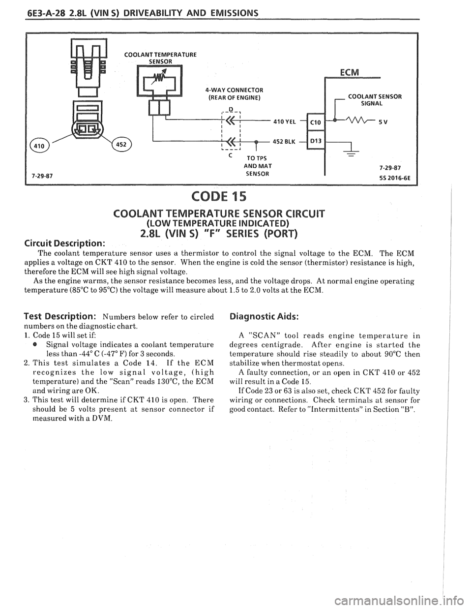
4-WAY CONNECTOR
(REAR OF ENGINE) COOLANT SENSOR
AND MAT
CODE 15
C0OLAN"FT"EMPERAWURE SENSOR CIRCUIT
(LOW TEMPERATURE INDICATED)
2.8L (VIN S) 'Tf3SEWlES (PORT)
Circuit Description:
The coolant temperature sensor uses a thermistor to control the signal voltage to the ECM. The ECM
applies a voltage on CKT 410 to the sensor. When the engine is cold the sensor (thermistor) resistance is high,
therefore the ECM will see high signal voltage.
As the engine warms, the sensor resistance becomes less, and the voltage drops. At normal engine operating
temperature
(85OC to 95°C) the voltage will measure about 1.5 to 2.0 volts at the ECM.
Test Description : Numbers below refer to circled
numbers on the diagnostic chart.
1. Code 15 will set if:
@ Signal voltage indicates a coolant temperature
less than
-44" C (-47" F) for 3 seconds.
2. This test simulates a Code 14. If the
ECM
recognizes the low signal voltage, (high
temperature) and the "Scan" reads
130°C, the ECM
and wiring are OK.
3. This test will determine if CKT 410 is open. There
should be 5 volts present at sensor connector if
measured with
a DVM.
Diagnostic Aids:
A "SCAN" tool reads engine temperature in
degrees centigrade. After engine is started the
temperature should rise steadily to about 90°C then
stabilize when thermostat opens.
A faulty connection, or an open in CKT 410 or 452
will result in a Code
15.
If Code 23 or 63 is also set, check CK'I' 452 for faulty
wiring or connections. Check terminals at sensor for
good contact. Refer to "intermittents" in Section
"B".
Page 683 of 1825
6E3-A-38 2.8b (VIM S) DRIVEABILITY AND EMISSIONS
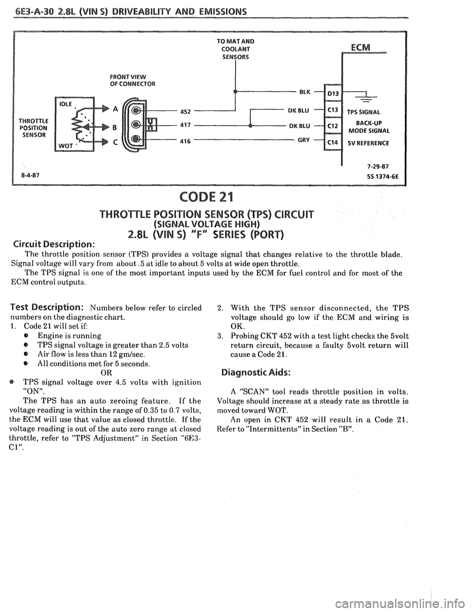
FRONT VIEW OF CONNECTOR
MODE SIGNAL
5V REFERENCE
THRBmLE POSiT10N SENSOR (TPS) CIRCUIT
(SIGNAL VOLTAGE HIGH)
2.8L (VIN S) ""F-SERIES (PORT)
Circuit Description:
The throttle position sensor (TPS) provides a voltage signal that changes relative to the throttle blade.
Signal voltage will vary from about
.5 at idle to about 5 volts at wide open throttle.
The TPS signal is one of the most important inputs used by the ECM for fuel control and for most of the
ECM control outputs.
Test Description: Numbers below refer to circled
numbers on the diagnostic chart.
1. Code 21 will set if:
@ Engine is running
@ TPS signal voltage is greater than 2.5 volts
@ Air flow is less than 12 gmlsec.
All conditions met for 5 seconds.
OR
@ TPS signal voltage over 4.5 volts with ignition
"ON".
The TPS has an auto zeroing feature. If the
voltage reading is within the range of 0.35 to 0.7 volts,
the ECM will use that value as closed throttle.
If the
voltage reading is out of the auto zero range at closed
throttle, refer to "TPS Adjustment" in Section
"6E3-
C1".
2. With the TPS sensor disconnected, the TPS
voltage should go low if the
ECM and wiring is
OK.
3. Probing CKT 452 with a test light checks the 5volt
return circuit, because a faulty 5volt return will
cause a Code 21.
Diagnostic Aids:
A "SCAN" tool reads throttle position in volts.
Voltage should increase at a steady rate as throttle
is
moved toward WOT.
An open in CKT 452 will result in a Code 21.
Refer to "Intermittents" in Section "B".
Page 685 of 1825
6E3-A-32 2.8L (VIN S) DRIVEABILITY AND EMISSIONS
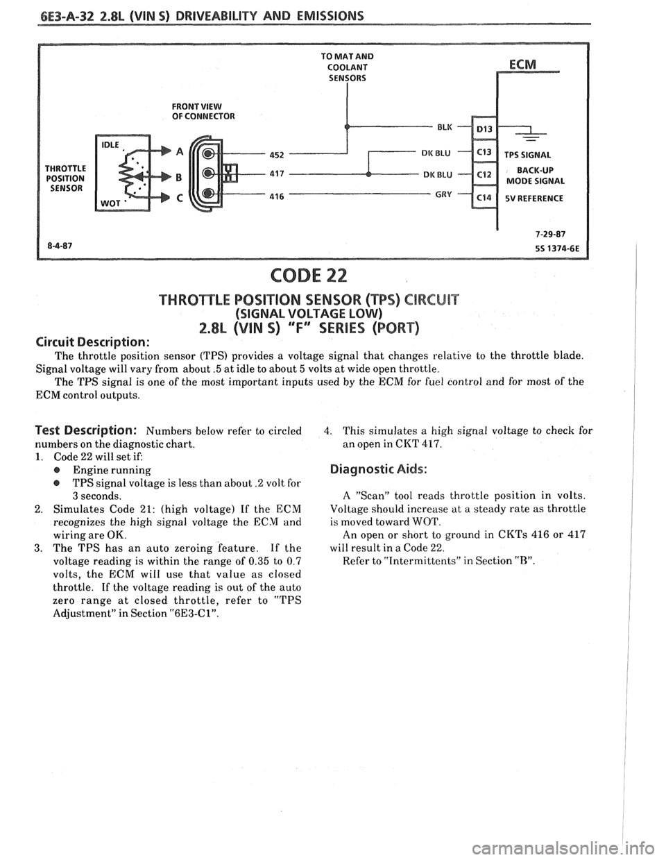
FRONT VIEW OF CONNECTOR
MODE SIGNAL
5V REFERENCE
CODE 22
f HRO"I$E"LE POSlTlON SENSOR ("BPS) ClRCUlT
(SIGNAL VOLTAGE LOW)
2.8L (VIN 9) "F" "SERIES (PORT)
Circuit Description:
The throttle position sensor (TPS) provides a voltage signal that changes relative to the throttle blade.
Signal voltage will vary from about
.5 at idle to about 5 volts at wide open throttle.
The TPS signal is one of the most important inputs used
by the ECM for fuel control and for most of the
ECM control outputs.
Test Description: Numbers below refer to circled
numbers on the diagnostic chart.
1. Code 22 will set if:
@ Engine running
@ TPS signal voltage is less than about .2 volt for
3 seconds.
2. Simulates Code 21: (high voltage) If the ECM
recognizes the high signal voltage the ECM and
wiring are OK.
3. The TPS has an auto zeroing feature. If the
voltage reading is within the range of
0.35 to 0.7
volts, the ECM will use that value as closed
throttle.
If the voltage reading is out of the auto
zero range at closed throttle, refer to "TPS
Adjustment" in Section
"6E3-Cl".
4. This simulates a high signal voltage to check for
an open in CKT
417.
Diagnostic Aids:
A "Scan" tool reads throttle position in volts.
Voltage should increase at a steady rate as throttle
is moved toward WOT.
An open or short to ground in CKTs 416 or 417
will result in a Code
22.
Refer to "Intermittents" in Section "B".
Page 687 of 1825
6E3-8-34 2.8L (VIN S) DRIVEABILITY AND EMISSIONS
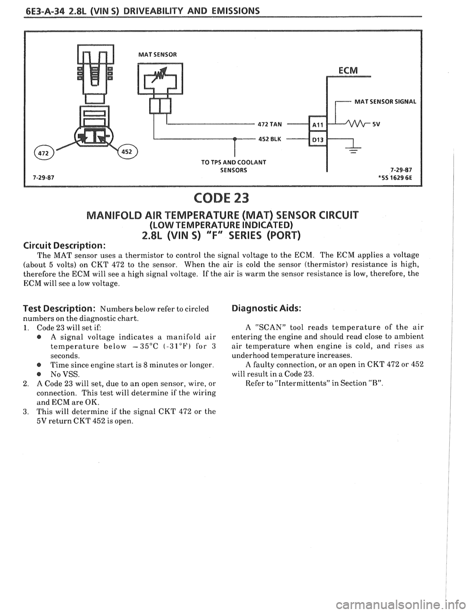
MAT SENSOR
MAT SENSOR SIGNAL
TO TPS AND COOLANT
SENSORS
CODE 23
MANIFOLD AIR TEMPERAWRE (MAq SENSOR CIRCUIT
(LOW TEMPERATURE INDICATED)
2.8L (VIN S) "F"" SERIES (PORT)
Circuit Description:
The MAT sensor uses a thermistor to control the signal voltage to the ECM. The ECM applies a voltage
(about 5 volts) on CKT 472 to the sensor. When the air is cold the sensor (thermistor) resistance is high,
therefore the ECM will see a high signal voltage. If the air is warm the sensor resistance is low, therefore, the
ECM will see
a low voltage.
Test Description: Numbers below refer to circled
numbers on the diagnostic chart.
1. Code 23 will set if:
@ A signal voltage indicates a manifold air
temperature below
-35°C (-32°F) for 3
seconds.
@ Time since engine start is 8 minutes or longer.
@ NoVSS.
2. A Code 23 will set, due to an open sensor, wire, or
connection. This test will determine if the
wiring
and ECM are OK.
3. This
will determine if the signal CKT
472 or the
5V return CKT 452 is open.
Diagnostic Aids:
A "SCAN" tool reads temperature of the air
entering the engine and should read close to ambient
air tetnperature when engine is cold, and rises as
underhood temperature increases.
A faulty connection, or an open in CKT 472 or 452
will result in a Code 23.
Refer to "Intermittents" in Section
"B".
Page 689 of 1825
6E3-A-36 2.8L (VlN 5) DRIVEABILIW YW EMISSIONS
- PARK OR NEUTRAL
CODE 24
VEHICLE SPEED SENSOR (VSS) CIRCUIT
2.8L (VIN 5) ""FYMIES (PORT)
Circuit Description:
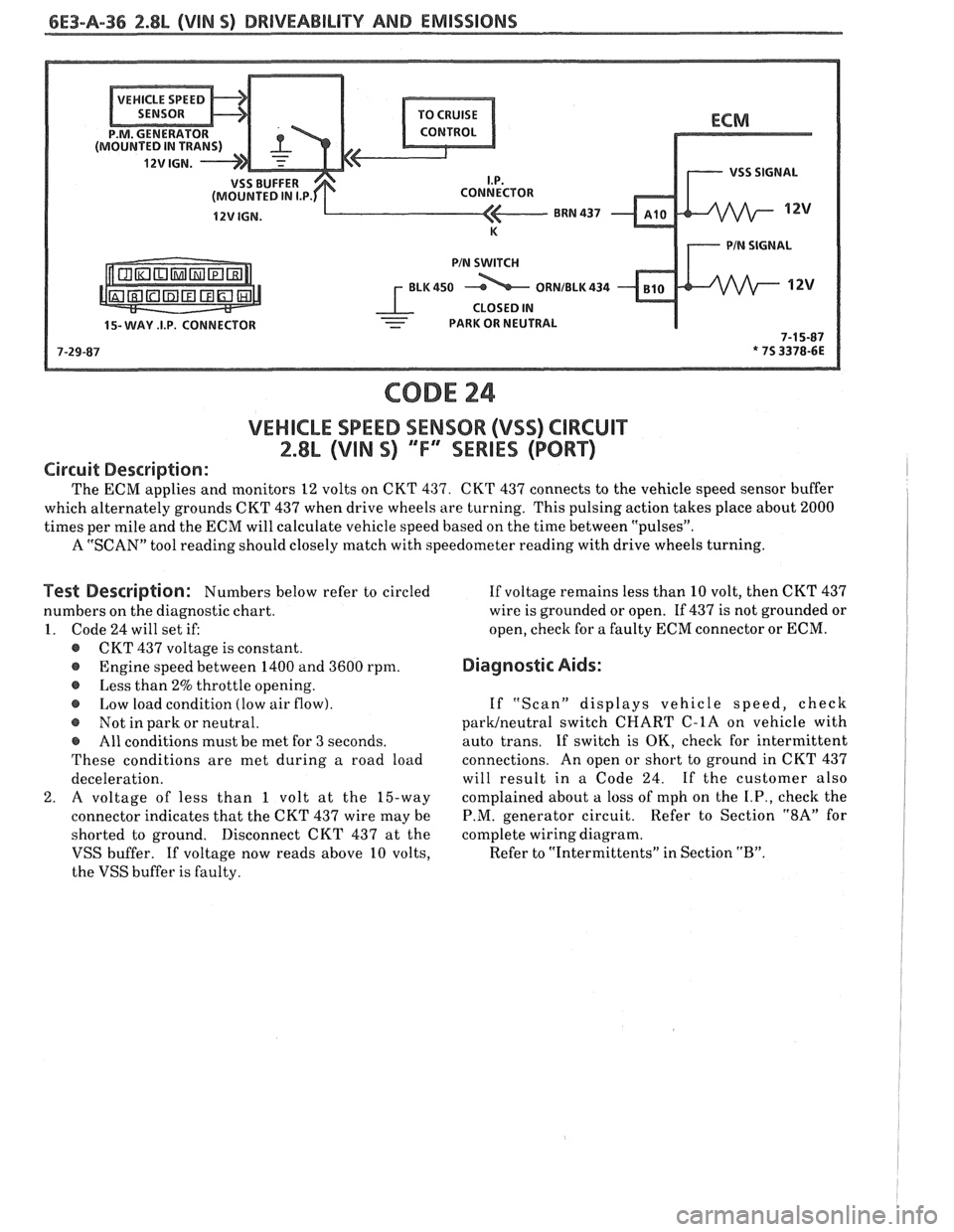
The ECM applies and monitors 12 volts on CKT 437. CKT 437 connects to the vehicle speed sensor buffer
which alternately grounds CKT
437 when drive wheels are turning. This pulsing action takes place about 2000
times per mile and the ECM will calculate vehicle speed based on the time between "pulses".
A "SCAN" tool reading should closely match with speedometer reading with drive wheels turning.
Test Description: Numbers below refer to circled
numbers on the diagnostic chart.
1. Code
24 will set if:
@ CKT 437 voltage is constant.
@ Engine speed between 1400 and 3600 rpm.
o Less than 2% throttle opening.
Low load condition (low air flow).
@ Not in park or neutral.
e All conditions must be met for 3 seconds.
These conditions are met during a road load
deceleration.
2. A voltage of less than 1 volt at the 15-way
connector indicates that the CKT
437 wire may be
shorted to ground. Disconnect CKT
437 at the
VSS buffer.
If voltage now reads above 10 volts,
the VSS buffer is faulty. If
voltage remains less than
10 volt, then CKT 437
wire is grounded or open. If 437 is not grounded or
open,
check for a faulty ECM connector or ECM.
Diagnostic Aids:
If "Scan" displays vehicle speed, check
paruneutral switch CHART C-1A on vehicle with
auto trans.
If switch is OK, check for intermittent
connections. An open or short to ground in CKT
437
will result in a Code 24. If the customer also
complained about
a loss of mph on the I.P., check the
P.M. generator circuit. Refer to Section "8A" for
complete wiring diagram.
Refer to "Intermittents" in Section
"B".
Page 693 of 1825
6E3-A-40 2.8L (VIN 5) DRIVEABILITY AND EMISSIONS
VENT FILTER
450 BLWHT ITCH SIGNAL -
CODE 32
EGR SYSTEM FAILURE
2.8L (VIN S) "F" "SERIES (PORT)
Circuit Description:
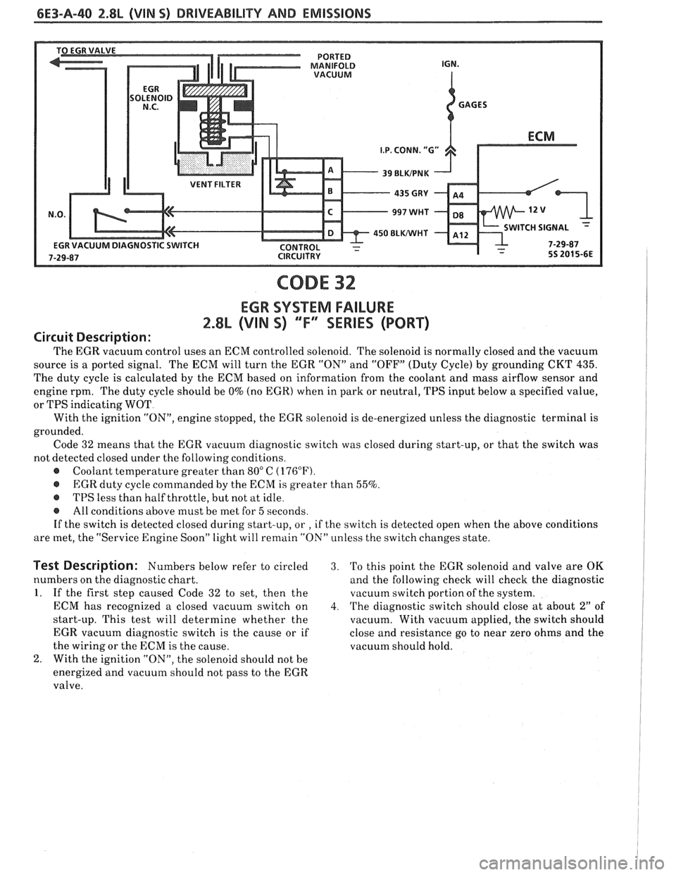
The EGR vacuum control uses an ECM controlled solenoid. The solenoid is normally closed and the vacuum
source is a ported signal. The ECM will turn the EGR "ON" and "OFF" (Duty Cycle) by grounding CKT
435.
The duty cycle is calculated by the ECM based on information from the coolant and mass airflow sensor and
engine rpm. The duty cycle should be
0% (no EGR) when in park or neutral, TPS input below a specified value,
or TPS indicating WOT
With the ignition
"ON", engine stopped, the EGR solenoid is de-energized unless the diagnostic terminal is
grounded. Code 32 means that the EGR vacuum diagnostic switch was closed during start-up, or that the switch was
not detected closed under the following conditions.
@ Coolant temperature greater than 80" C (176°F).
@ EGR duty cycle commanded by the ECM is greater than 55%.
@ TPS less than half throttle, but not at idle.
@ All conditions above must be met for 5 seconds.
If the switch is detected closed during start-up, or
, if the switch is detected open when the above conditions
are met, the "Service Engine Soon" light will remain "ON" unless the switch changes state.
Test Description: Numbers below refer to circled 3. 'Po this point the EGR solenoid and valve are OK
numbers on the diagnostic chart. and the following check will check the diagnostic
1. If the first step caused Code 32 to set, then the vacuutn switch portion of the system.
ECM has recognized a closed vacuum switch on
4. The diagnostic switch should close at about 2" of
start-up. This test will determine whether the
vacuum. With vacuum applied, the switch should
EGR vacuum diagnostic switch is the cause or if close and resistance go to near zero ohms and the
the wiring or the ECM is the cause. vacuum should hold.
2. With the ignition "ON", the solenoid should not be
energized and vacuum should not pass to the EGR
valve.
Page 710 of 1825
BRIVEABILIW AND EMISSIONS 2.8L (VlN 9) 6E3-B-1
SECTION B
SYMPTOMS
"TABLE OF CONTENTS
............................................................. Before Starting Page B-l
lntermittents............................................................... PageB-2
HardStart......,.......................................................... PageB-2
...................................................... Hesitation, Sag, Stumble Page 8-3
....................................................... Surges and/or Chuggle Page B-3
.............................................. Lack of Power, Sluggish, or Spongy Page B-4
...................................................... DetonationISpark Knock
Page 8-4
.................................... .................... Cuts Out, Misses ..O Page €3-5
Backfire............,...................................................... Page8-5
.......................................................... Poor Fuel Economy Page B-6
........................................................... Dieseling, Run-on. Page 8-6
........................................ Rough, Unstable, or Incorrect Idle, Stalling Page B-6
............................................. Excessive
Exhaust Emissions or Odors Page B-7
....................................... Restricted Exhaust
System Check (Chart 6-1) Page 8-8
BEFORE STARTING
Before using this section you should have
performed the DIAGNOSTIC CIRCUIT CHECK
and found out that:
1. The ECM and "Service Engine Soon" light are
operating.
2. There are no trouble codes stored, or there is a
trouble code but no "Service Engine Soon" light.
Verify the customer complaint, and locate the
correct SYMPTOM below. Check the items
indicated under that symptom.
If the ENGINE CRANKS BUT
WILL NOT
RUN, see CHART
A-3.
Several of the symptom procedures below call
for a careful visual check. This check should
include: ECM
grounds for being clean and tight.
@ Vacuum hoses for splits, kinks, and proper
connections, as shown on Emission Control
Information label.
@ Air leaks at throttle body mounting and intake
manifold.
@ Air leaks between MAF sensor and throttle
body.
Ignition wires for cracking, hardness, proper
routing, and carbon tracking.
@ Wiring for proper connections, pinches, and cuts.
The importance of this step cannot be stressed
too strongly
- it can lead to correcting a problem
without further checks and can save valuable time.
Page 711 of 1825
6E3-B-2 2.8L (VIN 5) DRIVEABILITY AND EMISSIONS
Problem may or may not turn "ON" the "Service Engine SoonJ' light, or store a code.
DO NOT use the trouble code charts in Section
"A" for intermittent problems. The fault must be
present to locate the problem. If a fault is
intermittent, use of trouble code charts may result
in replacement of good parts.
@ Most intermittent problems are caused by
faulty electrical connections or wiring. Perform
careful check as described at start of Section
"B". Check for:
@ Poor mating of the connector halves, or
terminals not fully seated in the connector
body (backed out).
@ Improperly formed or damaged terminals.
All connector terminals in problem circuit
should be carefully reformed to increase
contact tension.
@ Poor terminal to wire connection. This
requires removing the terminal from the
connector body to check. See "Introduction"
to Section
"6E".
@ If a visual check does not find the cause of the
problem, the car can be driven with a voltmeter
connected to a suspected circuit. A "Scan" tool
can also be used for monitoring input signals to
the ECM to help detect intermittent conditions.
An abnormal voltage, or "Scan" reading, when
the problem occurs, indicates the problem may
be in that circuit. If the wiring and connectors
check OK and a trouble code was stored for a
circuit having a sensor, except for Codes
43, 44,
and 45, substitute a known good sensor and
recheck. An
intermittent "Service Engine Soon" light
with no stored code may be caused by:
@ Ignition coil shorted to ground and arcing at
spark plug wires or plugs.
@ "Service Engine Soon" light wire to ECM
shorted to ground. (CKT 419).
@ Diagnostic "Test" terminal wire to ECM,
shorted to
ground.(CKT 451)
@ ECM power grounds. See ECM wiring
diagrams.
@ Loss of trouble code memory. To check,
disconnect TPS and idle engine until "Service
Engine Soon" light comes "ON". Code
22 should
be stored, and kept in memory when ignition is
turned "OFF". If not, the ECM is faulty.
@ Check for an electrical system interference
caused by a defective relay, ECM driven
solenoid, or switch. They can cause
a sharp
electrical surge. Normally, the problem will
occur when the faulty component is operated.
@ Check for improper installation of electrical
options, such as lights, 2-way radios, etc.
@ EST wires should be kept away from spark plug
wires, distributor wires, distributor housing,
coil, and generator. Wire from ECM to
distributor (CKT
453) should be a good
connection.
@ Check for open diode across A/C compressor
clutch, and for other open diodes (see wiring
diagrams).
HARD START
Definition: Engine cranks OK, but does not start for a long
time. Does eventually run, or may start hut immediately dies.
@ Perform careful check as described at start of -
Section "B".
@ Make sure driver is using correct starting
procedure.
@ CHECK:
- TPS for sticking or binding or a high TPS
voltage with the throttle closed (should read
less than
,700 volts).
- High resistance in coolant sensor circuit or
sensor itself. See Code 15 chart or with
a.
"Scan" tool compare coolant temperature with
ambient temperature on
a cold engine. 8
- Fuel pressure CHART A-7. Water contaminated
fuel.
EGR operation. Be sure valve seats properly and
is not staying open. See CHART C-7.
Both injector fuses (visually inspect).
Ignition system
- Check distributor for:
Proper output with ST-125.
Worn shaft.
Bare and shorted wires.
Pickup coil resistance and connections.
Loose ignition coil ground.
Moisture in distributor cap.
If problem exists in cold weather, check cold start
valve. See CHART A-9.