1988 PONTIAC FIERO roof
[x] Cancel search: roofPage 4 of 1825
GENERAL INFORMATION OA-1
SECTION (DA
GENERAL NFORMAT
CONTENTS
................................... General Description OA- 1 Prevailing Torque Fasteners ......................... OA-2
...................................... Body Number Plate OA- 1 Recommendations For Fastener Reuse ........ OA-2
..................... Vehicle Identification Number OA- 1 Vehicle Lifting Procedures ............ ., ............. OA-2
......................................... Metric Fasteners OA- 1 Precautions Against Tipping ........................ OA-7
................... Fastener Strength Identification OA-2 Automotive Abbreviations ................... .... 0.4- 1 1
GENERAL DESCRIPTION
Only general information appears in this section. left
of the windshield, see Figure 2. Refer to Figure 3
Detailed specifications on major units are given at the for detailed "VIN" code information.
For Engine V.I.
end of each respective section of this manual. N. Location, refer to Figure
4.
BODY NUMBER PLATE METRIC FASTENERS
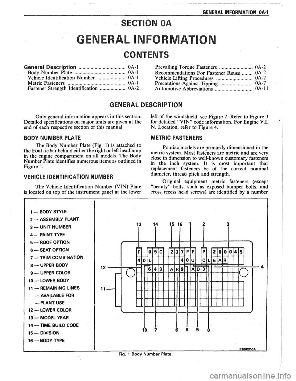
The Body Number Plate (Fig. 1) is attached to
Pontiac models are primarily dimensioned in the
the front tie bar behind either the right or left
headlamp metric system, Most fasteners are metric and are very in the engine On The close in dimension to well-known customary fasteners Number Plate identifies numerous items as outlined in in the inch system. It is most important that Figure 1. re~lacement fasteners be of the correct nominal
VEHICLE IDENTIFICATION NUMBER d&meter, thread pitch and strength.
Original equipment metric fasteners (except
The Vehicle Identification Number (VIN) Plate "beauty" bolts, such
as exposed bumper bolts, and
is located on top of the instrument panel at the lower cross
recess head screws) are identified by a number
1 -- BODY STYLE
2 ASSEMBLY PUNT
3 -- UNIT NUMBER
4 -- PAINT TYPE
5 - ROOF OPTION
6 -- SEAT OPTION
7 - TRIM COMBINATION
8 - UPPER BODY
9 - UPPER COLOR
10 -- LOWER BODY
11 - REMAINING LINES
- AVAILABLE FOR
--PLANT
USE
12 - LOWER COLOR
13 - MODEL YEAR
14 -- TIME BUILD CODE
15 - DIVISION
16 - BODY TvPE
6200224A
Fig. 1 Body Number Plate
Page 55 of 1825
18-12 AIR CONDITIONING
ELEGTRICAWACUUM SYSTEM
DIAGNOSIS
When diagnosing problems in the electrical sys-
tems of the air conditioning system, consult section
8A.
LEAK TESTING THE REFRIGERANT
SYSTEM
Whenever a refrigerant leak is suspected in the
system or a service operation performed which results
in disturbing lines or connections, it is advisable to
test for leaks.
Liquid Leak Detectors
There are a number of locations (fittings,
valves, etc.) on the air conditioning system where a
liquid leak detector solution may be used to pinpoint
refrigerant leaks.
By applying test solution to the area in question
with the swab that is attached to the bottle cap, bub-
bles will form within seconds if there is a leak.
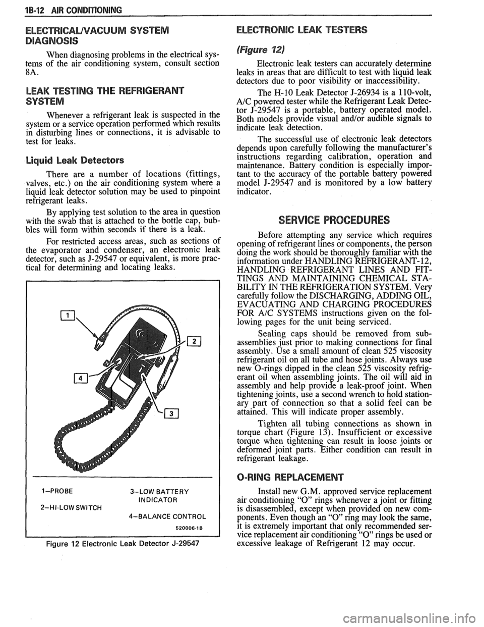
For restricted access areas, such as sections of
the evaporator and condenser, an electronic leak
detector, such as
5-29547 or equivalent, is more prac-
tical for determining and locating leaks.
3-LOW BATTERY
INDICATOR
2-HI-LOW SWITCH
4-BALANCE CONTROL
Figure 12 Electronic Leak Detector J-29547
ELECTRONIC LEAK TESTERS
(Figure 12)
Electronic leak testers can accurately determine
leaks in areas that are difficult to test with liquid leak
detectors due to poor visibility or inaccessibility.
The H-10 Leak Detector 5-26934 is a 110-volt,
A/C powered tester while the Refrigerant Leak Detec-
tor J-29547 is a portable, battery operated model.
Both models provide visual
and/or audible signals to
indicate leak detection.
The successful use of electronic leak detectors
depends upon carefully following the manufacturer's
instructions regarding calibration, operation and
maintenance. Battery condition is especially impor-
tant to the accuracy of the portable battery powered
model
5-29547 and is monitored by a low battery
indicator.
SERVICE PROCEDURES
Before attempting any service which requires
opening of refrigerant lines or components, the person
doing the work should be thoroughly familiar with the
information under HANDLING REFRIGERANT- 12,
HANDLING REFRIGERANT LINES AND FIT-
TINGS AND MAINTAINING CHEMICAL STA-
BILITY IN THE REFRIGERATION SYSTEM. Very
carefully follow the DISCHARGING, ADDING OIL,
EVACUATING AND CHARGING PROCEDURES
FOR
A/C SYSTEMS instructions given on the fol-
lowing pages for the unit being serviced.
Sealing caps should be removed from sub-
assemblies just prior to making connections for final
assembly. Use a small amount of clean 525 viscosity
refrigerant oil on all tube and hose joints. Always use
new O-rings dipped in the clean 525 viscosity refrig-
erant oil when assembling joints. The oil will aid in
assembly and help provide a leak-proof joint. When
tightening joints, use a second wrench to hold station-
ary part of connection so that
a solid feel can be
attained. This will indicate proper assembly.
Tighten all tubing connections as shown in
torque chart (Figure
13). Insufficient or excessive
torque when tightening can result in loose joints or
deformed joint parts. Either condition can result in
refrigerant leakage.
O-RING REPWCEMENT
Install new G. M. approved service replacement
air conditioning
"0" rings whenever a joint or fitting
is disassembled, except when provided on new com-
ponents. Even though an
"0" ring may look the same,
it is extremely important that only recommended ser-
vice replacement air conditioning
"0" rings be used or
excessive leakage of Refrigerant 12 may occur.
Page 102 of 1825
BUMPERS 28-1
SECTION 2B
BUMPERS
NOTICE: These fasteners are important attaching parts in that they could affect the performance of vital parts and
systems,
andlor could result in major repair expense. They must be replaced with one of the same part number or with an
equivalent
part if replacement becomes necessary. Do not use a replacement part of lesser quality or substitute design.
Torque values must be used as specified during reassembly to assure proper retention of all parts. There is to be no
welding as it may result in extensive damage and weakening of the metal.
NOTICE: The anti-theft label on some major sheet metal, engines, and transmissions must be masked prior to
painting, rustproofing, undercoating, etc. The mask MUST be removed following the above operations. Failure to keep
the label clean and readable may result in liability for violation of Federal Vehicle Theft Prevention Standard, and subject
the vehicle owner to possible suspicion that the part was stolen.
CONTENTS
General Description ................................ 2B-1 On-Vehicle Service ..................................... 2B-4
........................................... ..................... Service Procedures .. ........... 2B- 1 Specifications 2B-5
GENERAL DESCRIPWIBN
The bumpers on all Pontiac automobiles are remover.
Install new tape (double-coated neoprene
designed so that the vehicle can withstand a collision foam type)
to the back side of the rub strip.
into a fixed barrier at
5 mph. After absorbing the
energy of a collision, the bumpers restore themselves After
rub strip is installed, roll along entire
to their original position. surface with a roller
in order to insure a good bond.
The front and rear bumper fascias are made of
urethane. Urethane will withstand minor impact and
return to its original shape. Some front bumper fascias
are integral with the front end panel.
Some models use both steel and aluminum
bumper reinforcements. Usage is based on
EPA weight
class requirements.
BUMPER FASCIA RUB STRIPS
Some front and rear fascia rub strips are made of
a shiny plastic material. If a rub strip of this type loses
its lustre, the original shine can be restored by using
GM Plastic Cleaner or its equivalent. Follow directions
on the label.
SERVICE PROCEDURES
RUB STRIPS
Remove and Replace
Some plastic rub strips have an adhesive tape
backing (similar to a body side molding) and some have
studs or retaining tabs. In order to properly remove the
adhesive tape and avoid paint damage to the fascia, use
either a release agent or a heat lamp to soften the bond
of the adhesive tape to the fascia. In some cases, it will
be necessary to replace the rub strip with a new rub
strip instead of reusing the old one.
If the old rub strip is salvagable, remove all tape
from the back side of the rub strip as previously
described. Wipe strip clean with a wax and adhesive
FRONT BUMPER FASCIA (FRONT END PANEL)
Removal
Place a jack stand under fascia assembly before
removing bolts to prevent it from dropping down when
fascia attaching bolts are removed. Fascia will pivot on
the opposite end when one end is disconnected. Do not
rotate energy absorber any more than necessary to
align mounting holes.
1. Remove fascia attaching bolts and fascia to
fender attaching screws on right and left side, and
remove fascia and spacers.
2. If energy absorber is to be replaced, remove the
bolts and nuts from the front of the unit and the
nut from the stud at the rear.
Installation
1. Install energy absorber if removed.
2. Support fascia during installation to prevent
rotation of energy absorbers.
3. Install spacers and bolts at fascia to energy
absorber brackets.
4. Install fascia to fender attaching screws.
5. Check for proper clearance.
6. If adjustment is required to align fascia, loosen
energy absorber mounting bolts and position as
required (holes are slotted). Adjustment side to
side can be made by loosening fascia bracket
bolts. Torque all bolts and nuts. (See
Specifications.)
Page 434 of 1825
ENGINE FUEL 6C.3
a Fuel feed and return pipes are secured to the
underbody with clamps and screw assemblies.
The pipes should be inspected occasionally for
leaks, kinks or dents.
e Follow the same routing as the original pipe.
e Pipes must be properly secured to the frame to
prevent chafing. A minimum of 6 mm
(1/4")
clearance must be maintained around a pipe to
prevent contact and chafing.
MPFl Fuel Pipes
Due to the fact that fuel pipes are under high
pressure, these systems require special consideration for service.
Many feed and return pipes use screw couplings
with
"0" Rings. Any time these fittings are loosened
to service or replace components, ensure that:
a A backup wrench is used while loosening and
tightening the fitting.
e Check all "0" rings at fitting locations (if
applicable) for cuts or any damage and replace
any that appear worn or damaged.
e Use correct torque when tightening fittings.
If pipes are replaced always use original
equipment parts, or parts that meet GM
specifications.
Fuel and Vapor Hoses
NOTICE: Fuel and vapor hoses are specially
manufactured. If replacement becomes necessary,
it is important to use only replacement hoses
meeting GM Specification 6163-M. These hoses
are identified with the words "Fluoroelastomer"
on them. Hoses not so marked could cause early
failure, or fail to meet emission standards.
e Do not use rubber hose within 4" of any part of
the exhaust system, or within
10" of the catalytic
converter.
FUEL PUMP
The electric fuel pump is in the fuel tank. The
tank has an outlet for a vapor return system. Any vapor
which forms is returned to the fuel tank along with hot
fuel through a separate line. This greatly reduces any
possibility of vapor lock by keeping cool fuel from the
tank constantly circulating through the fuel pump.
FUEL PUMP RELAY
To control fuel pump operation, a fuel pump
relay is used.
When the ignition switch is turned to "RUN"
position, the fuel pump relay activates the electric fuel
pump for
1.5 to 2.0 seconds to prime the injector(s). If
the ECM does not receive reference pulses from the
distributor after this time, the ECM signals the relay
to turn off the fuel pump. The relay will once again
activate the fuel pump when the
ECM receives
distributor reference pulses.
Fuel Filter
CAUTION: To reduce the risk of fire
and personal injury, it is necessary
to
relieve the fuel system pressure
before servicing fuel system
components. (See Fuel System
Pressure Relief.)
The inline filters can be found on the rear
crossmember of the vehicle. Always use a backup
wrench any time that the fuel filter is removed or
installed. Also make sure that a good
"0" Ring is used
at all screw couple locations. Torque on fittings is
30
N-m (22 lb. ft.).
FUEL TANK
The fuel tank is usually located under the rear of
the vehicle and a number of shapes and sizes are used
depending on the application.
The tank is held in place by two metal straps,
hinged (with a bolt through the hinge) and secured at
the opposite end with a nut and bolt assembly.
Anti-squeak pieces are used on top of the tank to
reduce rattles and other annoying noises.
The fuel tank, cap and lines should be inspected
for road damage, whch could cause leakage. Inspect
fuel cap for correct sealing and indications of physical
damage. Replace any damaged or malfunctioning
parts.
Before attempting service of any type on the fuel
tank, always
(1) remove negative battery cable from
battery, (2) place "no smoking" signs near work areas,
(3) be sure to have C02 fire extinguisher handy, (4)
wear safety glasses and
(5) siphon or pump fuel into an
explosion proof container.
Fuel Filler Gap
The fuel tank filler neck is equipped with a
screw-type cap. The threaded part of the cap requires
several turns counterclockwise to remove. The long
threaded area is designed to allow any remaining fuel
tank pressure to escape while the cap is being removed.
A built-in torque-limiting device prevents
overtightening. To install, turn the cap clockwise until
a clicking noise is heard. This signals that the correct
torque has been reached and the cap is fully seated.
N OTI G E: If a fuel filler cap requires replacement,
use only a cap with the same features. Failure to
use the correct cap can result in a serious
malfunction of the system.
Available on some models is an electric locking
fuel filler cap. Information on this option will be found
in Section
9E.
FUEL TANK FILLER NECK
To help prevent refueling with leaded gasoline,
the fuel filler neck on gasoline engine cars has a built-in
restrictor and deflector. The opening in the restrictor
will only admit the smaller unleaded gas nozzle spout,
which must be fully inserted to bypass the deflector.
Attempted refueling with a leaded gas nozzle or failure
Page 723 of 1825
6E3-Cl-4 2.8L (VIN S) DRIVEABILITY AND EMISSIONS
BarWNeutral Switch (Auto Only)
The ParWNeutral (PIN) switch indicates to the
ECM when the transmission is in Park or Neutral.
This information is used for the TCC and the IAC
valve operation.
Important
Vehicle should not be driven with ParWNeutral
switch disconnected as idle quality will be affected
and a possible false Code
24 (VSS).
See Section "$A" for more information on the PIN
switch, which is part of the neutrallstart and backup
light switch assembly.
NC '"n" Signal
This signal tells the ECM that the A/C selector
Switch is turned on, and that the pressure cycling
switch is closed. The ECM uses this to adjust the idle
Speed when the air conditioning is working.
If this signal is not available to the ECM, idle may
be rough, especially when the
A/C compressor cycles.
The voltage at ECM terminal "B8" should equal
battery voltage when
AIC is requested and the
pressure cycling switch is closed.
The signal at
B8 will cause the ECM to turn on the
A/C clutch by energizing the A/C relay.
Distributor Reference Signal
The distributor sends a signal to the ECM to tell it
both engine RPM and crankshaft position. See EST
System for further information.
To read the codes, use a "Scan" tool or ground the
diagnostic terminal with the engine not running and
the ignition on. The "Service Engine Soon" light will
flash Code 12 three times and
then flash each code
stored in memory three times. All codes stored in
memory would have been read when Code 12 was
flashed again. No new codes can be stored when in the
Diagnostics Mode (diagnostics lead grounded).
This
eliminates confusion while the system is being worked
on. To clear the codes from memory:
@ Ignition off
@ Remove fuse located in a weather proof holder
located near the battery for 30 seconds.
Since the ECM can have
a failure which may
effect only one circuit, following the Diagnostic
Procedures in this section will determine which circuit
has a problem and where it is. If
a diagnostic chart indicates that the ECM
connections or ECM is the cause of
a problem and the
ECM is replaced, but does not correct the problem, one
of the following may be the reason:
€9
connections. - The diagnostic chart will say "ECM
connections or ECM. The terminals may have to be
removed from the connector in order to check them
properly.
@ The ECM or PROM is not correct for the
application.
- The incorrect components may cause a
malfunction and may or may not set a code.
@ The problem is intermittent. - This means that
the problem is not present at the time the system is
being checked. In this case, refer to the "Symptoms"
portion of the manual and make a careful physical
inspection of all portions of the system involved.
@ Shorted solenoid, relay coil, or harness. -
Solenoids and relays are turned "ON" and "OFF" by
the
ECM,using internal electronic switches called
"Drivers". Each driver is part of
a group of four called
"Quad-drivers". Failure of one driver can damage any
other driver in the set.
Solelloid and relay coil
resistance must measure more than 20 ohms. Less
resistance will cause early failure of the ECM
"driver". A shorted solenoid, relay coil, or harness,
with a GMP4 computer, will not damage the ECM, but
will cause the component to be inoperative.
Before replacing an ECM, be sure to check the coil
resistance of all solenoids and relays controlled by the
ECM. See ECM wiring diagram for the
solenoid(s)
and relay(s) and the coil terminal identification.
534636 or BT 8405 testers or equivalent provide
a fast, accurate means of checking for a shorted coil or
a short to battery voltage.
@ The PROM may be faulty. - Although these
rarely fail, it operates as part of the ECM. Therefore,
it could be the cause of the problem. Substitute a
known good PROM.
@ The replacement ECM may be faulty. - After the
ECM is replaced, the system should be rechecked for
proper operation. If the diagnostic chart again
indicates the ECM is the problem, substitute
a known
good ECM. Although this is a rare condition, it could
happen.
ECM
A faulty ECM will be determined in the diagnostic
charts or
by a Code 55.
PROM
A faulty PROM may result in a Code 51.
Page 1198 of 1825
REPAIR PROCEDURES
PUSH NARROW
PICK BETVVEEN
TERMINAL AND
CONNECTOR BODY
RE-FORM LOCKING TANG
RE-FORMING THE LOCKING TANG
REPAIRING WEATHER PACK@
(Environmental) CONNECTORS
Weather Pack@ or weatherproof connectors
provide environmental protection on certain
electrical circuits. This protection consists of a
moisture-proof rubber flexible seal between the
two connector halves and rubber cable seals
attached to each terminal. The terminals and
the cable
seals are secured by a hinged secon-
dary lock on small Weather Pack@ connectors
and by plastic terminal retainers on large
Weather Pack@ connectors.
If a Weather PackB connector requires
repair, do not replace the Weather Pack@ parts
with other types of connectors and temrinals.
Also, do not omit either the large seal or the
cable seals when making a repair.
Instruction in the disassemly, repair, and
assembly of both small and large Weather
PackR connectors follows. The instruction is
divided into steps. Only perform those steps
necessary to make the repair.
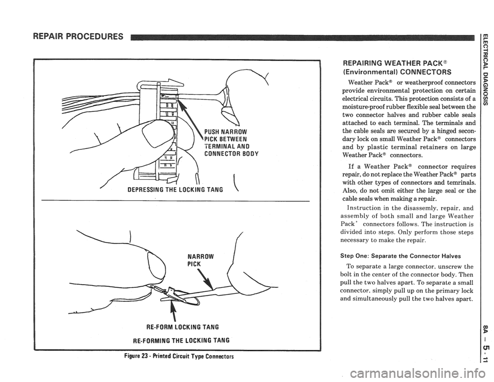
Step One: Separate the Connector Halves
To separate a large connector, unscrew the
bolt in the center of the connector body. Then
pull the two halves apart. To separate a small
connector, simply pull up on the primary lock
and simultaneously pull the two halves apart.
Figure 23 - Printed Circuit Type Connectass
Page 1594 of 1825
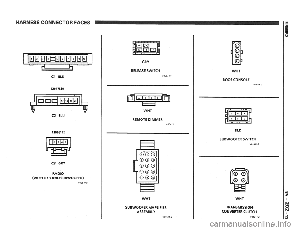
HARNESS CONNECTOR FACES
C1 BLK
12047530
C2 BLU
CRY
RELEASE SWITCH
WHT
REMOTE DIMMER
V00412 1
C3 GRY
RADIO
(WITH UK3 AND SUBWOOFER)
V00579 0
SUBWOOFER AMPLIFIER
ASSEMBLY
V00576.0
WHT
ROOF CONSOLE
V00515.0
BLK
SUBWOOFER SWITCH
V00577.0
WHT
TRANSMISSION
CONVERTER CLUTCH
V040 17.2
Page 1682 of 1825
GENERAL INFORMATION - F STYLE 1 H-1
SECTION IH
GENERAL NFORMAT
NOTICE: The anti-theft label found on some major sheet metal, engines, and transmissions must be masked
prior to painting, rustproofing, undercoating, etc. The mask
must be removed following the above operations.
Failure to keep the label clean and readable may result in liability for violation of Federal Vehicle Theft Prevention
Standard, and subject the vehicle owner to possible suspicion that the part was stolen.
Lock Cylinder Coding
..................................... I H-1 Chip Resistant Plastisol Material .................... 1 H-8
...................................................... Lubrication 1 H-2 Flexible Exterior Plastic Parts ......................... 1H-9
Adhesive Body Side Moldings ......................... 1H-3 Metal Replacement Parts Finishing ................ lH-13
Waterleak Diagnosis and Repair ..................... 1H-3 Interior Plastic Trim Parts Finishing .............. 1H-13
.................................................... Anticorrosion Treatment ................................ IH-4 Special Tools I H- 14
LOCK CYL!NDER CODING o Check key operation in the lock cylinder.
KEY IDENTIFICATION AND USAGE
REPLACEMENT LOCK CYLINDERS
The lock cylinder keyway is designed so that
other model keys will not enter a current model lock
cylinder. Two noninterchangeable keys are used.
CB Square headed key is used in the ignition lock
cylinder.
o Oval headed key is used in all other lock
cylinders.
Key identification is obtained from the four
character key code stamped on the knockout portion
of the key head and an identification letter stamped on
the key shank. After the code number has been
recorded by the owner, the plugs should be knocked
out of the key head. From these numbers, the lock
combination can be determined by use of a code list
(available to owners of key cutting equipment from
equipment suppliers). If key code numbers are not
available from records or from the knockout plug, the
lock combination (tumbler numbers and position) can
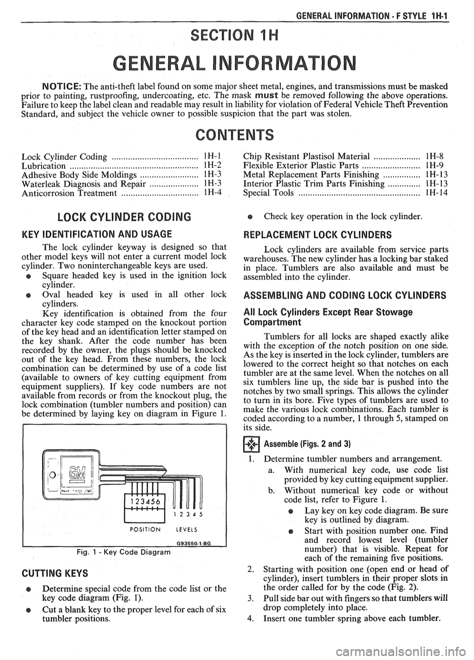
be determined by laying key on diagram in Figure
1.
I POSITION LEVELS I
Fig. 1 - Key Code Diagram
CUTTING KEYS
Lock cylinders are available from service parts
warehouses. The new cylinder has a locking bar staked
in place. Tumblers are also available and must be
assembled into the cylinder.
ASSEMBLING AND CODING LOCK CYLINDERS
All Lock Cylinders Except Rear Stowage
Compartment
Tumblers for all locks are shaped exactly alike
with the exception of the notch position on one side.
As the key is inserted in the lock cylinder, tumblers are
lowered to the correct height so that notches on each
tumbler are at the same level. When the notches on all
six tumblers line up, the side bar is pushed into the
notches by two small springs. This allows the cylinder
to turn in its bore. Five types of tumblers are used to
make the various lock combinations. Each tumbler is
coded according to a number,
1 through 5, stamped on
its side.
Assemble (Figs. 2 and 3)
1. Determine tumbler numbers and arrangement.
a. With numerical
key code, use code list
provided by key cutting equipment supplier.
b. Without numerical
key code or without
code list, refer to Figure
1.
o Lay key on key code diagram. Be sure
key is outlined by diagram.
Determine special code from the code list or the
key code diagram (Fig.
1). 3.
o Cut a blank key to the proper level for each of six
tumbler positions.
4.
Start with position number one. Find
and record lowest level (tumbler
number) that is visible. Repeat for
each of the remaining five positions.
Starting with position one [open end or head of
cylinder), insert tumblers in their proper slots in
the order called for by the code (Fig.
2).
Pull side bar out with fingers so that tumblers will
drop completely into place.
Insert one tumbler spring above each tumbler.