1988 PONTIAC FIERO fuel type
[x] Cancel search: fuel typePage 2 of 1825
1988
SER
This manual applies to the 1988 Pontiac Firebird Models.
It contains the latest product information available at the
time of publication approval. lnformation pertaining to
the operation of the vehicle is contained in the Owner's
Manual which accompanies each vehicle. The right is
reserved to make changes at any time without notice.
Any references to brand names in this manual is intended
merely as an example of the types of
lubricant% tools,
materials, etc, recommended for use in servicing 1988
Pontiac Models. In all cases, an equivalent may be used.
PONTIAC DIVISION
GENERAL
MOTORS CORPORATION
PONTIAC, MICHIGAN 48053
1987 General Motors Corp. All Rights Reserved.
No part of this publication may be reproduced, stored in any
retrieval system or transmitted in any form or by any means,
including but not limited to electronic, mechanical,
photocopying, recording or otherwise, without the prior written
permission of General Motors Corp. This includes all text,
illustrations, tables and charts.
S-881 OF 9-87 Printed in Canada
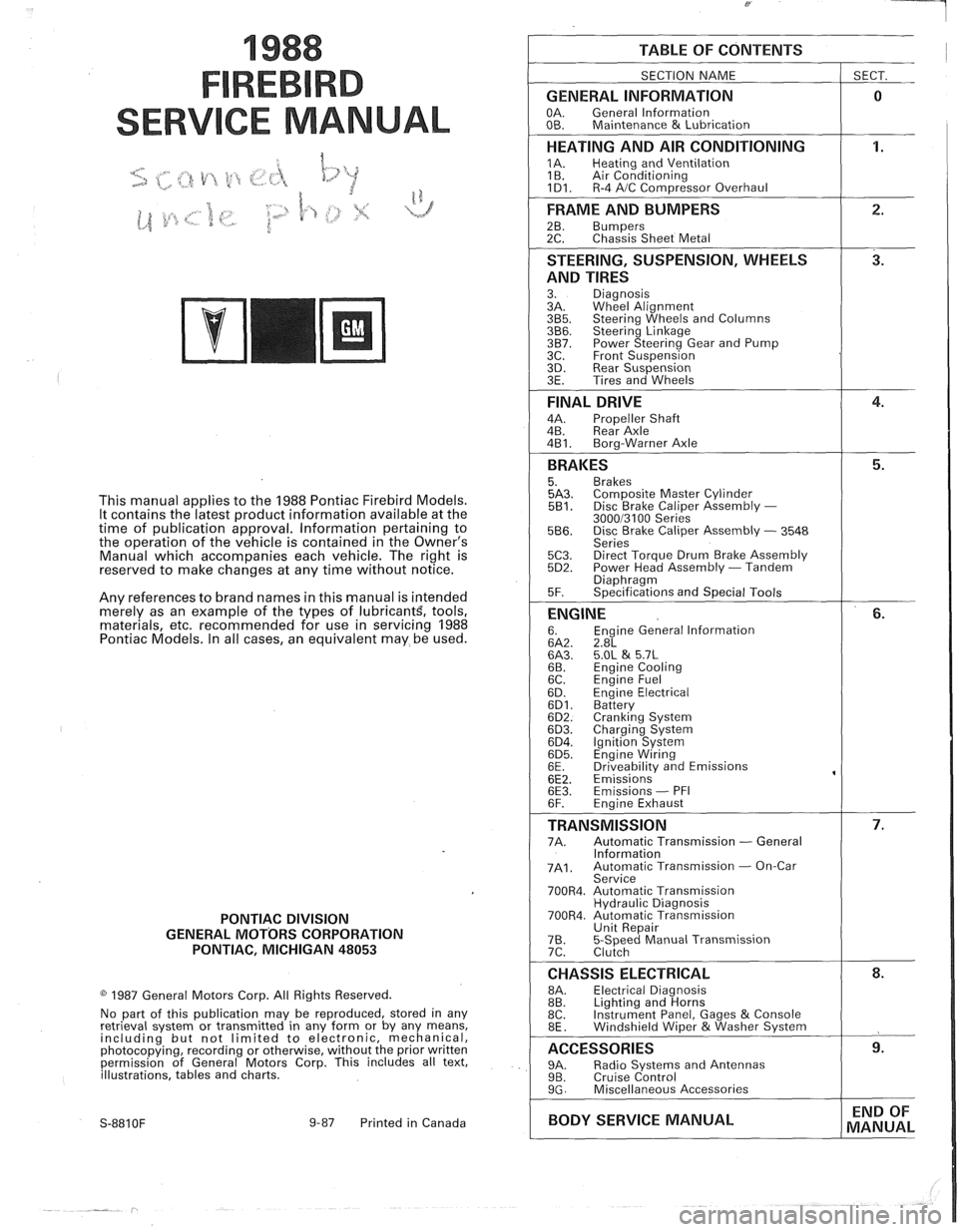
TABLE OF CONTENTS
SECTION NAME
GENERAL INFORMATION
OA. General lnformation
OB. Maintenance & Lubrication
1 SECT.
HEATING AND AIR CONDITIONING
1A. Heating and Ventilation
1 B. Air Conditioning
1D1. R-4 AIC Com~ressor Overhaul
FRAME AND BUMPERS
2B. Bumpers 2C. Chassis Sheet Metal
STEERING, SUSPENSION, WHEELS
AND TIRES
3. Diagnosis
3A. Wheel Alignment
3B5. Steering Wheels and Columns 3B6. Steering Linkage 3B7. Power Steering Gear and Pump
3C. Front Suspension
3D. Rear Suspension
3E. Tires and Wheels
FINAL DRIVE
4A. Propeller Shaft
4B. Rear Axle
4B1. Bora-Warner Axle
BRAKES 5. Brakes 5A3. Comoosite Master Cvlinder 5B1. Disc r rake Caliper ~ssembly - 300013100 Series 5B6. Disc Brake Caliper Assembly - 3548
Series
5C3. Direct Torque Drum Brake Assembly 5D2. Power Head Assembly - Tandem Diaohraam 5F. ~~ecifications and Special Tools
ENGINE 6. Engine General lnformation 6A2. 2.8L 6A3. 5.OL & 5.7L 6B. Engine Cooling
6C. En~ine Fuel
6D. ~ngine Electrical 6D1. Battery 6D2. Cranking System 6D3. Charging System 6D4. Ignition System 6D5. Engine Wiring
6E. Driveabilitv and Emissions
6E2. ~missions' 6E3. Emissions - PFI
6F. Engine Exhaust
TRANSMISSION 7A. Automatic Transmission - General
lnformation
7A1. Automatic Transmission - On-Car
Service
700R4. Automatic Transmission Hydraulic Diagnosis
700R4. Automatic Transmission Unit Repair
76. 5-Speed Manual Transmission
7C. Clutch
CHASSIS ELECTRICAL 8A. Electrical Diagnosis
8B. Lighting and Horns
8C. Instrument
Panel, Gages
& Console
8E. Windshield Wiper &Washer System
ACCESSORIES 9A. Radio Systems and Antennas 9B. Cruise Control 9G. Miscellaneous Accessories
I BODY SERVICE MANUAL END
OF
MANUAL
Page 5 of 1825
OA-2 GENERAL INFORMATION
VIN NUMBER PLATE
LOCATION
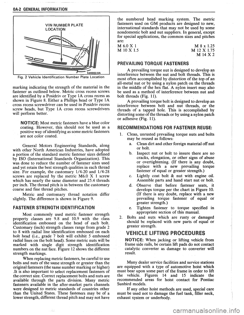
Fig. 2 Vehicle Identification Number Plate Location
marking indicating the strength of the material in the
fastener as outlined below. Metric cross recess screws
are identified by a Posidriv or Type
1A cross recess as
shown in Figure 8. Either a Phillips head or Type
1A
cross recess screwdriver can be used in Posidriv recess
screw heads, but Type
1A cross recess screwdrivers
will perform better.
NOTICE: Most metric fasteners have a blue color
coating. However, this should not be used as a
positive way of identifying as some metric fasteners
are not color coated.
General Motors Engineering Standards, along
with other North American Industries, have adopted
a portion of the standard metric fastener sizes defined
by
IS0 (International Standards Organization). This
was done to reduce the number of fastener sizes used
and yet retain the best strength qualities in each thread
size. For example, the customary 1/4-20 and 1/4-28
screws are replaced by the metric
M6.0 X 1 screw
which has nearly the same diameter and
25.4 threads
per inch. The thread pitch is in between the customary
coarse and fine thread pitches.
Metric and customary thread notation differ
slightly. The difference is shown in Figure 9.
FASTENER STRENGTH ODENTIFIGATION
Most commonly used metric fastener strength
property classes are 9.8 and 10.9 with the class
identification embossed on the head of each bolt.
Customary (inch) strength classes range from grade 2
to 8 with radial line identification embossed on each
bolt head
(i.e., grade 7 bolt will exhibit 5 embossed
radial lines on the bolt head). Some metric nuts will be
marked with single digit strength identification
numbers on the nut face. Figure 12 shows the different
strength markings.
When replacing metric fasteners, be careful to use
bolts and nuts of the same strength or greater than the
original fasteners (the same number marking or higher)
.It is also important to select replacement fasteners of
the correct size. Correct replacement bolts and nuts are
available through the parts division. Many metric
fasteners available in the after-market parts channels
were designed to metric standards of countries other
than the United States. These fasteners may be of a
lower strength, different thread pitch and may not have the
numbered head marking system. The metric
fasteners used on GM products are designed to new,
international standards that may not be used by some
nondomestic bolt and nut suppliers. In general, except
for special applications, the common sizes and pitches
are:
M 6.0
X 1
M 8 x 1.25
M 10 X 1.5 M 12 X 1.75
M 14x2 I
PREVAILING TORQUE FASTENERS
A prevailing torque nut is designed to develop an
interference between the nut and bolt threads. This is
most often accomplished by distortion of the top of an
all-metal nut or by using a nylon patch on the threads
in the middle of the hex flat.
A nylon insert may also
be used as a method of interference between nut and
bolt threads (Fig. 11).
A prevailing torque bolt is designed to develop an
interference between bolt and nut threads, or the
threads of a tapped hole. This is accomplished by
distorting some of the threads or by using a nylon patch
or adhesive (Fig. 11).
RECOMMENDATIONS FOR FASTENER REUSE: I
Clean, unrusted prevailing torque nuts and bolts
may be reused as follows:
a. Clean dirt and other foreign material off nut
or bolt.
b. Inspect nut or bolt to insure there are no
cracks, elongation, or other signs of abuse
or overtightening. (If there is any doubt,
replace with a new prevailing torque
fastener of equal or greater strength.)
c. Lightly coat bolt
& nut with engine oil.
Assemble parts and hand start nut or bolt.
d. Observe that before fastener seats, it
develops torque per the chart in Figure
10.
(If there is any doubt, replace with a new
prevailing torque fastener of equal or
greater strength.)
e. Tighten fastener to torque specified in
appropriate section of this manual.
Bolts and nuts which are rusty or damaged
should be replaced with new parts of equal or
greater strength.
VEHICLE LIF"TING PROCEDURES
NOTICE: When jacking or lifting vehicle from
frame side rails, be certain lift pads do not contact
catalytic converter as damage to converter will
result.
Many dealer service facilities and service stations
are equipped with a type of automotive hoist which
must bear upon some part of the frame in order to lift
the vehicle. Figures 14 and 15 indicate the
recommended areas for hoist contact for Pontiac
Sunbird models.
If any other hoist methods are used, special care
must be used not to damage the fuel tank, filler neck,
I
exhaust system or underbody. I
Page 20 of 1825

F CARLINE
ITEM 10
TransmissionRransaxle Service
The manual transmission or transaxle fluid does not
require changing. (Corvette only.) Change fluid in over-
drive unit every 30,000 miles (50 000 km).
For automatic transmissions or transaxles, change
both the fluid and filter every 15,000 miles (25 000 km) if
the car is mainly driven under one or more of these
conditions:
@ In heavy city traffic where the outside temperature
regularly reaches 90°F (32°C) or higher.
@ In hilly or mountainous terrain.
@ Frequent trailer pulling.
@ Uses such as found in taxi, police car or delivery
service.
If you do not use your car under any of these condi-
tions, change both the fluid and filter every 100,000 miles
(160 000 km). See you Owner's Manual for further
details.
ITEM 11
Spark Plug Service*
Replace spark plugs with type listed in your Owner's
Manual.
ITEM 12
Spark Plug Wire Inspection*
Clean wires and inspect for burns, cracks or other dam-
age. Check the wire boot fit at distributor and at spark plugs.
Replace wires as needed.
ITEM 13
Positive Crankcase Ventilation (PCV) Valve
Inspection*
Inspect valve for proper function. Replace valve if
necessary as well as any worn, plugged or collapsed
hoses.
ITEM 14
EGR System Service*
Conduct EGR System Service as referenced in the
EGR System Chart shown in the appropriate 6E Section.
Also, refer to your GM maintenance schedule booklet for
specific applications.
ITEM 15
Air Cleaner and PCV Filter Replacement*
On 1.6 and 2.0 liter engines, replace every 50,000
miles (80 000 km). On all other engines, replace every
30,000 miles (50 000 km). Replace more often under
dusty conditions. Ask your dealer for the proper replace-
ment interval for your driving conditions.
MAINTENANCE AND LUBRICATION 08-3
ITEM 16
Engine Timing Check*
Adjust timing to underhood label specifications. If
no specifications are shown, no adjustment is needed.
ITEM 17
Fuel Tank, Cap and Lines Inspection*
Inspect fuel tank, cap and lines (including fuel rails
and injection assembly, if so equipped) for damage or
leaks. Inspect fuel cap gasket for an even filler neck
imprint or any damage. Replace parts as needed.
ITEM 18
Thermostatically Controlled Air Cleaner
Inspection*
If your car is equipped, inspect all hoses and ducts
for proper hookup. Make sure valve works properly.
OWNER INSPECTIONS AND SERVICES
Listed below are inspections and services which
should be made by either you or a qualified technician at
the intervals shown to help ensure proper safety, emission
performance and dependability of your car. Take any
problems promptly to your dealer or another qualified
technician for service advice. Whenever repairs are neces-
sary, have them completed at once. For your safety and
that of others, any safety-related parts that could have
been damaged in an accident should be inspected and all
needed repairs should be done before operating your car.
Be sure to use the proper fluids and lubricants as shown in
Figure OB-2.
WHILE OPERATING YOUR VEHICLE
Automatic transmissionltransaxle shift indi-
cator operation - Make sure the indicator points to the
gear chosen.
Horn operation - Blow the horn occasionally to
make sure it works. Check all button locations.
I
Brake system operation -- Be alert to abnormal
sounds, increased brake pedal travel or repeated pulling to
one side when braking. Also, if a brake warning light
comes on or flashes, or the anti-lock warning light (if
equipped) comes on or remains on, something may be
wrong with part of the brake system. Have it inspected and
repaired at once.
Exhaust system operation - Be alert to any
changes in the sound of the system or any smell of fumes.
These are signs the system may be leaking or overheating.
.
Have it inspected and repaired at once. Also see "Engine
Exhaust Gas Caution (Carbon Monoxide)" and "Catalytic
Converter" in your Owner's Manual.
*An Emission Control Service
Page 23 of 1825
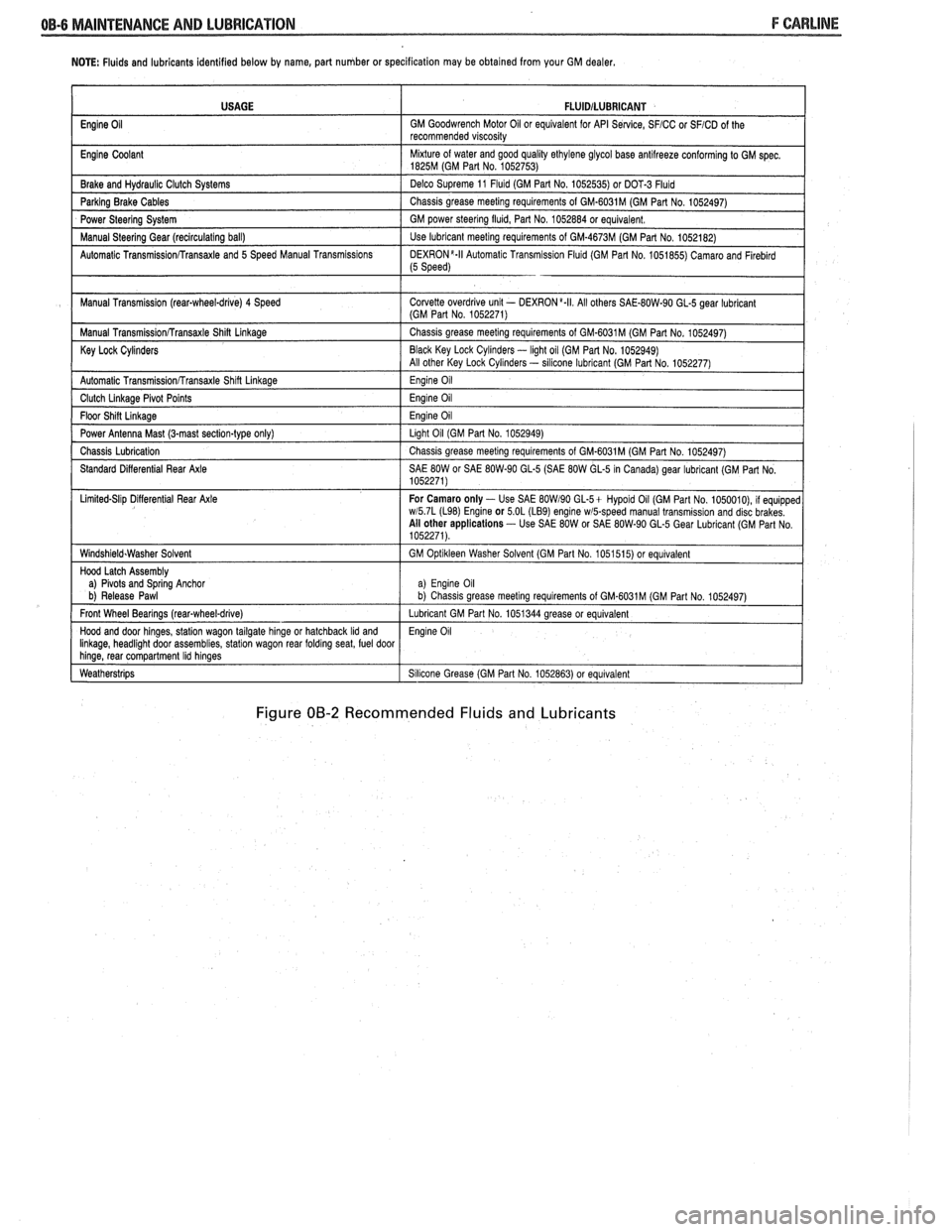
NOTE: Fluids and lubricants identified below by name, part number or specification may be obtained from your GM dealer.
Figure 00-2 Recommended Fluids and Lubricants
USAGE
Engine
Oil
Engine Coolant
Brake and
Hydraul~c Clutch Systems
Parking Brake Cables
Power Steering System
Manual
Steerlng Gear (reclrculat~ng ball)
Automatic
Transrn~ssionRransaxle and 5 Speed Manual Transm~ss~ons
Manual Transm~ssion (rear-wheel-drive) 4 Speed
Manual
Transm~ss~onRransaxle Shin Linkage
Key Lock Cylinders
Automatic Transmlss~onfrransaxle Shlft Llnkage
Clutch Llnkage Plvot Po~nts
Floor Sh~n L~nkage
Power Antenna Mast (3-mast sect~on-type only)
Chass~s Lubr~cation
Standard D~fferent~al Rear Axle
L~m~ted-Sl~p D~flerent~al Rear Axle
W~ndsh~eld.Washer Solvent
Hood Latch Assembly
a)
Plvots and Sprlng Anchor
b) Release Pawl
Front Wheel Bearings
(rearqwheel-drive)
Hood and door hlnges, statlon wagon tailgate hlnge or hatchback Ild and Ilnkage, headl~ght door assembl~es, statlon wagon rear foldrng seat, fuel door hlnge, rear compartment Ihd hlnges
Weatherstr~ps
FLUlDlLUBRlCANT
GM Goodwrench Motor 011 or equivalent for API Se~lce, SFICC or SFICD of the
recommended v~scos~ty
M~xture of water and good qual~ty ethylene glycol base antllreeze conforming to GM spec 1825M (GM Part No 1052753)
Delco Supreme 11
Fluld (GM Part No 1052535) or DOT-3 Fluld
Chass~s grease meetlng requirements of GM-6031M (GM Part No 1052497)
GM power
steerlng flu~d, Part No 1052884 or equivalent
Use lubricant meetlng requirements of GM-4673M (GM Part No 1052182)
DEXR0N'-II Automat~c Transm~ss~on Flu~d (GM Part No 1051855) Camaro and Flreblrd (5 Speed)
Corvette overdr~ve unlt - DEXRON a.II All others SAE-80W-90 GL-5 gear lubr~cant (GM Part No 1052271)
Chass~s grease meetlng requirements of GM-6031M (GM Part No 1052497)
Black Key Lock
Cyl~nders - light oil (GM Par1 No. 1052949)
All other Key Lock Cyl~nders - sllicone lubrlcant (GM Part No 1052277)
Eng~ne 011
Eng~ne 011
Eng~ne 011
Llght 011 (GM Part No 1052949)
Chass~s grease meetlng requirements of GM-6031M (GM Part No 1052497)
SAE
80W or SAE 80W-90 GL-5 (SAE 80W GL-5 In Canada) gear lubricant (GM Part No
1052271)
For Camaro only
- Use SAE BOW190 GL-5+ Hypold 011 (GM Part No 1050010), 11 equ~pped wl5 7L (L98) Englne or 5 OL (LB9) engine wmpeed manual transm~ss~on and disc brakes
All other applications - Use SAE 80W or SAE 80W-90 GL-5 Gear Lubr~cant (GM Part No
1052271)
GM
Opt~kleen Washer Solvent (GM Part No 1051515) or equ~valent
a) Eng~ne 011 b) Chass~s grease meet~ng requirements of GM.6031M (GM Part No 1052497)
Lubricant GM Part No 1051344 grease or equivalent
Eng~ne 011
S~l~cone Grease (GM Part No 1052863) or equivalent
Page 352 of 1825
2.8 LITER V-6 BA2-1
TER V-6 V N CODES RPO
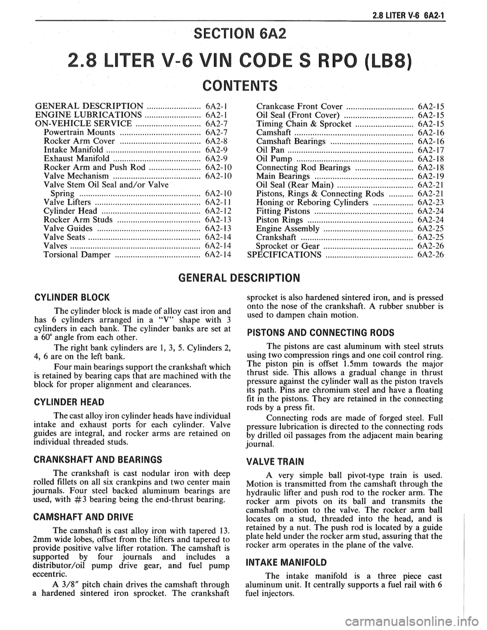
CONTENTS
GENERAL DESCRIPTION ........................ 6A2- 1
ENGINE LUBRICATIONS ......................... 6A2- 1
ON-VEHICLE SERVICE ............................. 6A2-7
Powertrain Mounts .................................... 6A2-7
Rocker Arm Cover .................................... 6A2-8
Intake Manifold .......................................... 6A2-9
Exhaust Manifold ................................... 6A2-9
Rocker Arm and Push Rod ....................... 6A2- 10
Valve Mechanism
....................................... 6A2- 10
Valve Stem Oil Seal and/or Valve
Spring
.................... .. .. ... ................... 6A2- 10
Valve Lifters
............................................. 6A2- l l
Cylinder Head ............................................ 6A2- 12
Rocker Arm Studs
.................................... 6A2- 13
Valve Guides
........................................... 6A2- 13
Valve Seats
................................................ 6A2- 14
Valves
......................................................... 6A2- 14
Torsional Damper
..................................... 6A2- 14 Crankcase
Front Cover
.............................. 6A2- 15
Oil Seal (Front Cover)
........................... .... 6A2- 15
Timing Chain
& Sprocket .......................... 6A2- 15
Camshaft
................................................... 6A2- 16
Camshaft Bearings
................................... 6A2- 16
Oil Pan
........................................................ 6A2- 17
Oil Pump
.................................................. 6A2- 18
Connecting Rod Bearings .......................... 6A2- 18
Main Bearings
............................................ 6A2- 19
Oil Seal (Rear Main)
.................................. 6A2-2 1
Pistons, Rings & Connecting Rods ........... 6A2-2 1
Honing or Reboring Cylinders .................. 6A2-23
Fitting Pistons ............................................ 6A2-24
.............................................. Piston Rings 6A2-24
Engine Assembly ...................................... 6A2-25
.................................................. Crankshaft 6A2-25
........................................ Sprocket or Gear 6A2-26
..................................... SPECIFICATIONS 6A2-26
GENERAL DESCRIPTION
CYLINDER BLOCK
The cylinder block is made of alloy cast iron and
has 6 cylinders arranged in a "V" shape with 3
cylinders in each bank. The cylinder banks are set at
a
60" angle from each other.
The right bank cylinders are
1, 3, 5. Cylinders 2,
4, 6 are on the left bank.
Four main bearings support the crankshaft which
is retained by bearing caps that are machined with the
block for proper alignment and clearances.
CYLINDER HEAD
The cast alloy iron cylinder heads have individual
intake and exhaust ports for each cylinder. Valve
guides are integral, and rocker arms are retained on
individual threaded studs.
CRANKSHAFT AND BEARINGS
The crankshaft is cast nodular iron with deep
rolled fillets on all six crankpins and two center main
journals. Four steel backed aluminum bearings are
used, with
#3 bearing being the end-thrust bearing.
CAMSHAFT AND DRIVE
sprocket is also hardened sintered iron, and is pressed
onto the nose of the crankshaft.
A rubber snubber is
used to dampen chain motion.
PISTONS AND CONNECTING RODS
The pistons are cast aluminum with steel struts
using two compression rings and one coil control ring.
The piston pin is offset
1.5mm towards the major
thrust side. This allows a gradual change in thrust
pressure against the cylinder wall as the piston travels
its path. Pins are chromium steel and have a floating
fit in the pistons. They are retained in the connecting
rods by a press fit.
Connecting rods are made of forged steel. Full
pressure lubrication is directed to the connecting rods
by drilled oil passages from the adjacent main bearing
journal.
VALVE TRAIN
A very simple ball pivot-type train is used.
Motion is transmitted from the camshaft through the
hydraulic lifter and push rod to the rocker arm. The
rocker arm
~ivots on its ball and transmits the
camshaft
mot'ion to the valve. The rocker arm ball
locates on a stud, threaded into the head, and is
The camshaft is cast alloy iron with tapered 13. by a nut. The push rod is located by a guide
2mm wide lobes, offset from the lifters and tapered to plate held under the rocker arm stud, assuring that the
provide positive valve lifter rotation. The camshaft is arm Operates in the plane the
support& by four journals and includes a
distributor/oil pump drive gear, and fuel pump INTAKE MANIFOLD - - eccentric.
The intake manifold is a three piece cast
A
3/8" pitch chain drives the camshaft through
aluminum unit. It centrally supports a fuel rail with 6
a hardened sintered iron sprocket. The crankshaft
fuel injectors.
Page 381 of 1825
6A3-2 V-8 ENGINE
VALVE TRAIN
A very simple ball pivot-type train is used.
Motion is transmitted from the camshaft through the
hydraulic lifter and push rod to the rocker arm. The
rocker arm pivots on its ball and transmits the
camshaft motion to the valve. The rocker-arm ball is
retained by a nut.
HYDRAULIC VALVE LIFTERS
Hydraulic Valve Lifters are used to keep all parts
of the valve train in constant contact.
The hydraulic lifter assembly consists of: a roller,
the lifter body, which rides in the cylinder block boss,
a plunger, a push rod seat, a metering valve, a plunger
spring, a check ball and spring, a check ball retainer
and a push rod seat retainer.
When the lifter is riding on the low point of the
cam, the plunger spring keeps the plunger and push rod
seat in contact with the push rod.
When the lifter body begins to ride up the cam
lobe, the check ball cuts off the transfer of oil from the
reservoir below the plunger. The plunger and lifter
body then rise as a unit, pushing up the push rod and
opening the valve.
As the lifter body rides down the other side of the
cam, the plunger follows with it until the valve closes.
The lifter body continues to follow the cam to its low
point, but the plunger spring keeps the plunger in
contact with the push rod. The ball check valve will then
move off its seat and the lifter reservoir will
remain full.
INTAKE MANIFOLD
The intake manifold for those engines with
carburetors are made of cast iron or aluminum double
level design for efficient fuel distribution. An Exhaust
Gas Recirculation (EGR) port is also cast into the
manifold for the mixture of exhaust gases with the fuel
air mixture.
The intake manifold for those vehicles equipped
with
PFI is a cast aluminum unit. It centrally supports
a fuel rail with
8 fuel injectors.
EXHAUST MANIFOLDS
Two cast iron exhaust manifolds are used to
direct exhaust gases from the combustion chambers to
the exhaust system. The left hand side manifold
receives a heat shield that is used to route heated air
to the air cleaner. for better fuel vaporization during
warm-up.
COMBUSTION CHAMBERS
Combustion Chambers are cast to insure uniform
shape for all cylinders. Spark plugs are located between
the intake and exhaust valves. The contoured wedge
shape of the combustion chamber minimizes the
possibility of detonation, facilitates breathing and
provides swirling turbulence for smooth, complete
combustion.
ENGINE LUBRICATION
Full pressure lubrication through a full flow oil through drilled passages, to the camshaft and
filter, is furnished by a gear-type oil pump. The crankshaft to lubricate the bearings. The valve lifter oil
distributor, driven by a helical gear on the camshaft,
gallery feeds the valve lifters which, through hollow
drives the oil pump. The main oil gallery feeds oil,
push rods, feed the individually mounted rocker arms.
Page 406 of 1825
V-8 ENGINE 6A3-27
3. When finish honing
a cylinder bore to fit a piston,
the hone should be moved up and down at a
sufficient speed to obtain very fine uniform
surface finish marks in a cross-hatch pattern of
approximately
45" to 65" included angle. The
finish marks should be clean but not sharp, free
from imbedded particles and torn or folded
metal.
4. Permanently mark
the piston for the cylinder to
which it has been fitted and proceed to hone
cylinders and fit the remaining pistons.
NOTICE: Handle the pistons with care and do not
attempt to force them through the cylinder until
the cylinder has been honed to correct size as this
type piston can be distorted through careless
handling.
5. Thoroughly
clean the bores with hot water and
detergent. Scrub well with a stiff bristle brush and
rinse thoroughly with hot water. It is extremely
essential that a good cleaning operation be
performed. If any of the abrasive material is
allowed to remain in the cylinder bores, it will
rapidly wear the new rings and cylinder bores in
addition to the bearings lubricated by the
contaminated oil, the bores should be swabbed
and then wiped with a clean dry cloth. Cylinder
should not be cleaned with kerosene or gasoline.
Clean the remainder of the cylinder block to
remove the excess material spread during the
honing operation.
Piston Selection
1. Check USED piston to cylinder bore clearance as
follows:
a. Measure
the "Cylinder Bore Diameter"
with a telescope gage
"2-1/2" (64mm) from
top of cylinder bore").
b. Measure
the
"Piston Diameter" (at skirt
across center line of piston pin).
c. Subtract
piston diameter from cylinder bore
diameter to determine "Piston to Bore
Clearance".
d. Determine if piston to bore clearance is in
the acceptable range.
2. If
used piston is not acceptable, check Piston Size
Chart and determine if a new piston can be
selected to fit cylinder bore within the acceptable
range.
3. If
cylinder bore must be reconditioned, measure
new piston diameter (across center line of piston
pin) then hone cylinder bore to correct clearance
(preferable range).
4. Mark the piston to identify the cylinder for which
it was fitted.
OIL FILTER BYPASS VALVE
Inspection and Replacement
With the oil filter removed, check the spring and
fibre valve for operation. Inspect for a cracked or
broken valve. If replacement is necessary, the oil filter
adapter and bypass valve assembly must be replaced as an
assembly. Clean valve chamber in cylinder block
thoroughly. Torque retaining screws to specifications.
ENGINE ASSEMBLY
Removal
1. Disconnect battery.
2. Remove air cleaner.
3. Remove hood.
4. Drain radiator.
5. Remove lower radiator hose.
6. Remove upper fan shroud.
7. Remove upper radiator hose and coolant
recovery hose.
8. Remove transmission cooler lines.
9. Remove radiator.
10. Remove fan assembly.
1 1. Remove heater hoses.
12. Disconnect
carburetor linkage, includes cruise
control detent cable.
13. Remove vacuum brake booster line.
14. Remove
distributor cap and lay wiring aside.
15. Disconnect necessary wires and hoses.
16. Remove power steering
pump and lay aside.
17. Raise vehicle.
18. Remove exhaust
pipes at exhaust manifold.
19. Remove dust cover.
20. Remove converter bolts.
2 1. Disconnect starter wires.
22. Remove bell housing bolts.
23. Remove
motor mount through bolts.
24. Disconnect fuel lines
at fuel pump.
25. Lower vehicle.
26. Support transmission.
27. Remove
A.I.R./Converter pipe bracket.
28. Remove engine, include removing wire
from
bracket at rear left of engine.
Installation
1. Position engine
assembly in vehicle.
2. Attach
motor mount to engine brackets and
lower engine in place.
3. Remove engine lifting device.
4. Remove transmission floor jack.
5. Raise vehicle on hoist.
6. Install mount "through" bolts. Torque to
specifications.
7. Install bell housing bolts. Torque to
specifications.
8. On vehicles with automatic transmissions, install
I
converter to flywheel attaching bolts. Torque to
specifications.
9. Install flywheel splash shield of converter
housing cover as applicable. Torque attaching
bolts to specifications.
I
10. Install starter wires.
1 1. Connect fuel lines.
12. Connect exhaust pipe at manifold.
13. Lower vehicle on hoist.
14. Reinstall power steering pump, if so equipped.
15. Connect necessary wires and hoses.
Page 432 of 1825
ENGINE FUEL BC-1
SECTION 6C
NE FUEL
CONTENTS
General Description ..................................... 6C-1 Fuel
Cap ........................................................... 6C-3
.................................................. ............................................. Alcohol-In-Fuel 6C- 1 Fuel Filter Neck 6C-3
................... ............ Fuel Metering .................................................. 6C-2 Fuel Gage Sending Unit .. 6C-4
....................... ............................... Throttle Body Injection (TBI) .... 6C-2 Diagnosis ,. 6C-4 ................... Service
Procedures ............................................. 6C-4
Port Fuel Injection ...................................... 6C-2
Pressure Relief ........................................... 6C-4
Fuel Feed and Return Pipe
............................... 6C-2
Flow Test .................................................... 6C-4
Fuel Pipes (MPFI)
.......................................... 6C-3
Pressure Test - TBI ................................... 6C-4
Fuel and Vapor Hoses
....................................... 6C-3
Pressure Test - MPFI .................................... 6C-4
Fuel Pump ........................................................ 6C-3 ...................................................... Fuel Pump Relay .............................................. 6C-3 Fuel Tank 6C-4
Fuel Filter
......................................................... 6C-3 Accelerator Controls ...................................... 6C-5
Fuel Tank
....................................................... 6C-3
All new General Motors vehicles are certified by
the United States Environmental Protection Agency as
conforming to the requirements of the regulations for
the control of air pollution from new motor vehicles.
This certification is contingent on certain adjustments
being set to factory standards. In most cases, these
adjustment points either have been permanently
sealed and/or made inaccessible to prevent
indiscriminate or routine adjustment in the field. For
this reason, the factory procedure for temporarily
removing plugs, caps, etc., for purposes of servicing the
product must be strictly followed and, wherever
practicable, returned to the original intent of the
design.
GENERAL DESCRIPTION
All gasoline engines are designed to use only
unleaded gasoline. Unleaded gasoline must be used for
proper emission control system operation. Its use will
also minimize spark plug fouling and extend engine oil
life. Using leaded gasoline can damage the emission
control system and could result in loss of emission
warranty coverage.
All cars are equipped with an Evaporative
Emission System. The purpose of the system is to
minimize the escape of fuel vapors to the atmosphere.
Information on this system will be found in Section
6E2, or 6E3.
When working on the fuel system, there are
several things to keep in mind.
@ Any time fuel system is being worked on,
disconnect the negative battery cable
except for those tests where battery
Adhere to all Notices and Cautions.
Always keep a dry chemical (Class B) fire
extinguisher near the work area.
-
Always use a backup wrench when loosening or
tightening a screw couple fitting.
The torque on a screw fitting is
30 N-m (22 lb.
ft.).
Pipe is used on all MPFI, TPI, SFI, and TBI
applications. Fittings require the use of an
"0"
Ring. Replace all pipe with the same type of pipe
and fittings that were removed.
All fuel pipes must meet GM Specification
124-M, or its equivalent.
All fuel hoses must meet GM Specification
6163-M, or its equivalent.
Do not replace fuel pipe with fuel hose.
voltage is required.
@ On MPFI, TPI, SF1 and TBI systems, always A1cohol-ln-Fuel
relieve the line pressure before servicing any fuel Certain driveability complaints such as
system components. hesitation, lack of power, stall, no start, etc., may be
@ Do not repair the fuel system until you have read caused
by an excessive amount of alcohol-in-fuel. The
the copy and checked the illustrations relating to complaints
may be due to fuel system corrosion and
that repair. subsequent
fuel filter plugging, deterioration of rubber