1988 PONTIAC FIERO horn
[x] Cancel search: hornPage 2 of 1825
1988
SER
This manual applies to the 1988 Pontiac Firebird Models.
It contains the latest product information available at the
time of publication approval. lnformation pertaining to
the operation of the vehicle is contained in the Owner's
Manual which accompanies each vehicle. The right is
reserved to make changes at any time without notice.
Any references to brand names in this manual is intended
merely as an example of the types of
lubricant% tools,
materials, etc, recommended for use in servicing 1988
Pontiac Models. In all cases, an equivalent may be used.
PONTIAC DIVISION
GENERAL
MOTORS CORPORATION
PONTIAC, MICHIGAN 48053
1987 General Motors Corp. All Rights Reserved.
No part of this publication may be reproduced, stored in any
retrieval system or transmitted in any form or by any means,
including but not limited to electronic, mechanical,
photocopying, recording or otherwise, without the prior written
permission of General Motors Corp. This includes all text,
illustrations, tables and charts.
S-881 OF 9-87 Printed in Canada
TABLE OF CONTENTS
SECTION NAME
GENERAL INFORMATION
OA. General lnformation
OB. Maintenance & Lubrication
1 SECT.
HEATING AND AIR CONDITIONING
1A. Heating and Ventilation
1 B. Air Conditioning
1D1. R-4 AIC Com~ressor Overhaul
FRAME AND BUMPERS
2B. Bumpers 2C. Chassis Sheet Metal
STEERING, SUSPENSION, WHEELS
AND TIRES
3. Diagnosis
3A. Wheel Alignment
3B5. Steering Wheels and Columns 3B6. Steering Linkage 3B7. Power Steering Gear and Pump
3C. Front Suspension
3D. Rear Suspension
3E. Tires and Wheels
FINAL DRIVE
4A. Propeller Shaft
4B. Rear Axle
4B1. Bora-Warner Axle
BRAKES 5. Brakes 5A3. Comoosite Master Cvlinder 5B1. Disc r rake Caliper ~ssembly - 300013100 Series 5B6. Disc Brake Caliper Assembly - 3548
Series
5C3. Direct Torque Drum Brake Assembly 5D2. Power Head Assembly - Tandem Diaohraam 5F. ~~ecifications and Special Tools
ENGINE 6. Engine General lnformation 6A2. 2.8L 6A3. 5.OL & 5.7L 6B. Engine Cooling
6C. En~ine Fuel
6D. ~ngine Electrical 6D1. Battery 6D2. Cranking System 6D3. Charging System 6D4. Ignition System 6D5. Engine Wiring
6E. Driveabilitv and Emissions
6E2. ~missions' 6E3. Emissions - PFI
6F. Engine Exhaust
TRANSMISSION 7A. Automatic Transmission - General
lnformation
7A1. Automatic Transmission - On-Car
Service
700R4. Automatic Transmission Hydraulic Diagnosis
700R4. Automatic Transmission Unit Repair
76. 5-Speed Manual Transmission
7C. Clutch
CHASSIS ELECTRICAL 8A. Electrical Diagnosis
8B. Lighting and Horns
8C. Instrument
Panel, Gages
& Console
8E. Windshield Wiper &Washer System
ACCESSORIES 9A. Radio Systems and Antennas 9B. Cruise Control 9G. Miscellaneous Accessories
I BODY SERVICE MANUAL END
OF
MANUAL
Page 20 of 1825
F CARLINE
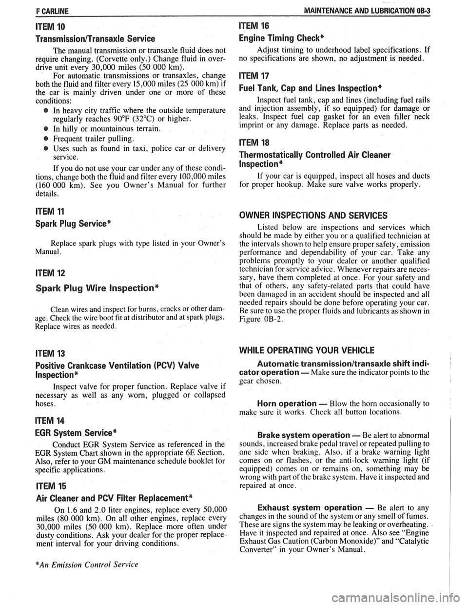
ITEM 10
TransmissionRransaxle Service
The manual transmission or transaxle fluid does not
require changing. (Corvette only.) Change fluid in over-
drive unit every 30,000 miles (50 000 km).
For automatic transmissions or transaxles, change
both the fluid and filter every 15,000 miles (25 000 km) if
the car is mainly driven under one or more of these
conditions:
@ In heavy city traffic where the outside temperature
regularly reaches 90°F (32°C) or higher.
@ In hilly or mountainous terrain.
@ Frequent trailer pulling.
@ Uses such as found in taxi, police car or delivery
service.
If you do not use your car under any of these condi-
tions, change both the fluid and filter every 100,000 miles
(160 000 km). See you Owner's Manual for further
details.
ITEM 11
Spark Plug Service*
Replace spark plugs with type listed in your Owner's
Manual.
ITEM 12
Spark Plug Wire Inspection*
Clean wires and inspect for burns, cracks or other dam-
age. Check the wire boot fit at distributor and at spark plugs.
Replace wires as needed.
ITEM 13
Positive Crankcase Ventilation (PCV) Valve
Inspection*
Inspect valve for proper function. Replace valve if
necessary as well as any worn, plugged or collapsed
hoses.
ITEM 14
EGR System Service*
Conduct EGR System Service as referenced in the
EGR System Chart shown in the appropriate 6E Section.
Also, refer to your GM maintenance schedule booklet for
specific applications.
ITEM 15
Air Cleaner and PCV Filter Replacement*
On 1.6 and 2.0 liter engines, replace every 50,000
miles (80 000 km). On all other engines, replace every
30,000 miles (50 000 km). Replace more often under
dusty conditions. Ask your dealer for the proper replace-
ment interval for your driving conditions.
MAINTENANCE AND LUBRICATION 08-3
ITEM 16
Engine Timing Check*
Adjust timing to underhood label specifications. If
no specifications are shown, no adjustment is needed.
ITEM 17
Fuel Tank, Cap and Lines Inspection*
Inspect fuel tank, cap and lines (including fuel rails
and injection assembly, if so equipped) for damage or
leaks. Inspect fuel cap gasket for an even filler neck
imprint or any damage. Replace parts as needed.
ITEM 18
Thermostatically Controlled Air Cleaner
Inspection*
If your car is equipped, inspect all hoses and ducts
for proper hookup. Make sure valve works properly.
OWNER INSPECTIONS AND SERVICES
Listed below are inspections and services which
should be made by either you or a qualified technician at
the intervals shown to help ensure proper safety, emission
performance and dependability of your car. Take any
problems promptly to your dealer or another qualified
technician for service advice. Whenever repairs are neces-
sary, have them completed at once. For your safety and
that of others, any safety-related parts that could have
been damaged in an accident should be inspected and all
needed repairs should be done before operating your car.
Be sure to use the proper fluids and lubricants as shown in
Figure OB-2.
WHILE OPERATING YOUR VEHICLE
Automatic transmissionltransaxle shift indi-
cator operation - Make sure the indicator points to the
gear chosen.
Horn operation - Blow the horn occasionally to
make sure it works. Check all button locations.
I
Brake system operation -- Be alert to abnormal
sounds, increased brake pedal travel or repeated pulling to
one side when braking. Also, if a brake warning light
comes on or flashes, or the anti-lock warning light (if
equipped) comes on or remains on, something may be
wrong with part of the brake system. Have it inspected and
repaired at once.
Exhaust system operation - Be alert to any
changes in the sound of the system or any smell of fumes.
These are signs the system may be leaking or overheating.
.
Have it inspected and repaired at once. Also see "Engine
Exhaust Gas Caution (Carbon Monoxide)" and "Catalytic
Converter" in your Owner's Manual.
*An Emission Control Service
Page 130 of 1825
STEERING. SUSPENSION. TIRES AND WHEELS DIAGNOSIS 3-5
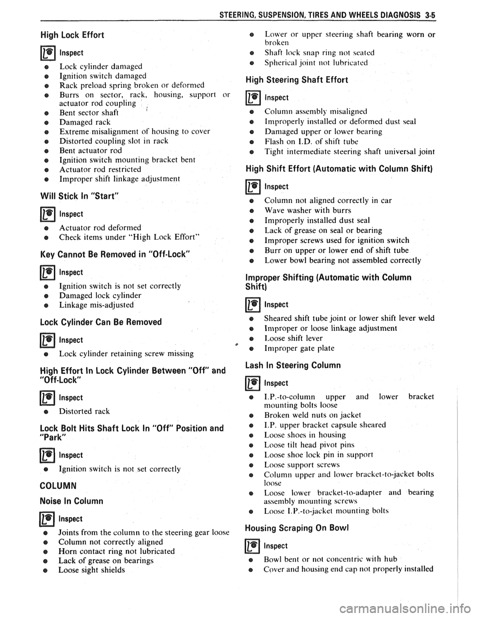
High Lock Effort
rn lnspect
e Lock cylinder damaged
e Ignition switch damaged
o Rack preload spring broken or deformed
e Burrs on sector, rack, housing, support or
actuator rod coupling
,
e Bent sector shaft
e Damaged rack
e Extreme misalignment of' housing to cover
e Distorted coupling slot in rack
e Bent actuator rod
e Ignition switch mounting bracket bent
e Actuator rod restricted
e Improper shift linkage adjustment
Will Stick In "Start"
rn lnspect
e Actuator rod deformed
e Check items under "High Lock Effort"
Key Cannot Be Removed in "Off-Lock"
rn lnspect
e Ignition switch is not set correctly
e Damaged lock cylinder
e Linkage mis-adjusted
Lock Cylinder Can Be Removed
Inspect
e Lock cylinder retaining screw missing
High Effort In Lock Cylinder Between "Off" and
"Off-Lock"
lnspect
o Distorted rack
Lock Bolt Hits Shaft Lock In "Off" Position and
"Park"
lnspect
e Ignition switch is not set correctly
COLUMN
Noise In Column
Inspect
e Joints from the column to the steering gear 1
e Column not correctly aligned
e Horn contact ring not lubricated
e Lack of grease on bearings
o Loose sight shields
o Lower or upper steering shaft bearing worn or
broken
e Shaft lock snap ring not seated
o Spherical joint not lubricated
High Steering Shaft Effort
e Column assembly misaligned
e Improperly installed or deformed dust seal
e Damaged upper or lower bearing
e Flash on I.D. of shift tube
e Tight intermediate steering shaft universal joint
High Shift Effort (Automatic with Column Shift)
rn lnspect
e Column not aligned correctly in car
e Wave washer with burrs
e Improperly installed dust seal
o Lack of grease on seal or bearing
e Improper screws used for ignition switch
e Burr on upper or lower end of shift tube
e Lower bowl bearing not assembled correctly
Improper Shifting (Automatic with Column
Shift)
rn lnspect
e Sheared shift tube joint or lower shift lever weld
e Improper or loose linkage adjustment
e 1,oose shift lever
e Improper gate plate
Lash In Steering Column
lnspect
e 1.P.-to-column upper and lower bracket
nlounting bolts loose
e Broken weld nuts on jacket
e I.P. upper bracket capsule sheared
e Loose shoes in housing
e Loose tilt head pivot pins
e Loose shoe lock pin in support
e Loose support screws
e Column upper and lower bracket-to-jacket bolts
loose
e Loose lower bracket-to-adapter and bearing
assembly mounting screws
e Loose 1.P.-to-jacket mounting bolts
Housing Scraping On Bowl
rn Inspect
e Bowl bent or not concentric with hub
e Cover and housing end cap not properly installed
Page 153 of 1825
385-2 STEERING WHEELS AND COLUMNS
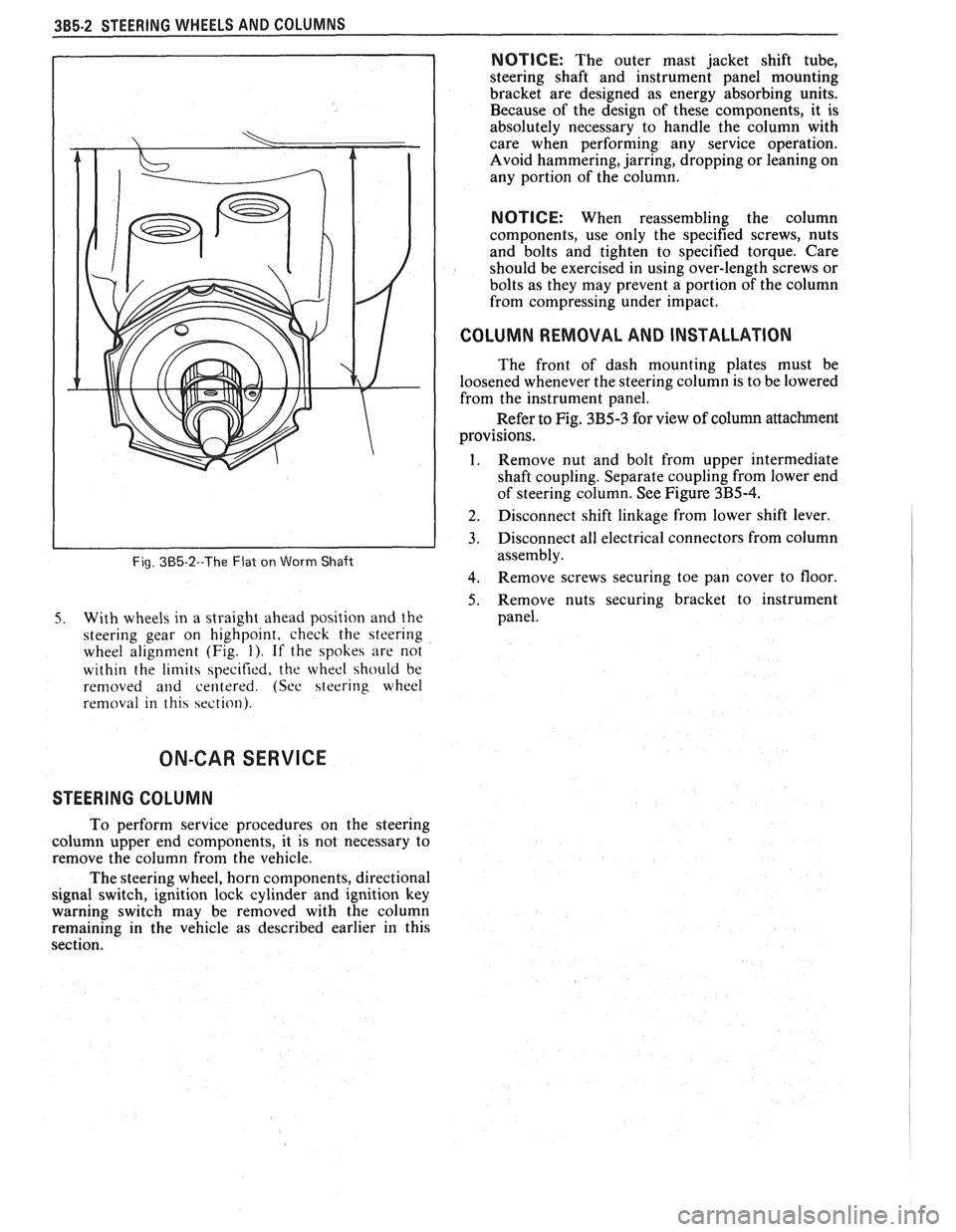
Fig. 385-2--The Flat on Worm Shaft
5. With wheels in a straight ahead position and the
steering gear on highpoint, check the steering
wheel alignment (Fig.
1). If the spokes are not
within the
limits specified, the wheel should be
removed
and centered. (See steering wheel
removal in this section).
NOTICE: The outer mast jacket shift tube,
steering shaft and instrument panel mounting
bracket are designed as energy absorbing units.
Because of the design of these components, it is
absolutely necessary to handle the column with
care when performing any service operation.
Avoid hammering, jarring, dropping or leaning on
any portion of the column.
NOTICE: When reassembling the column
components, use only the specified screws, nuts
and bolts and tighten to specified torque. Care
should be exercised in using over-length screws or
bolts as they may prevent a portion of the column
from compressing under impact.
I COLUMN REMOVAL AND INSTALLATION
The front of dash mounting plates must be
loosened whenever the steering column is to be lowered
from the instrument panel.
Refer to Fig. 3B5-3 for view of column attachment
provisions.
1. Remove nut and bolt from upper intermediate
shaft coupling. Separate coupling from lower end
of steering column. See Figure
3B5-4.
] 2. Disconnect shift linkage from lower shift lever.
3. Disconnect all electrical connectors from column
assembly.
4. Remove screws securing toe pan cover to floor
5. Remove nuts securing bracket to instrument
panel.
ON-CAR SERVICE
STEERING COLUMN
To perform service procedures on the steering
column upper end components, it is not necessary to
remove the column from the vehicle.
The steering wheel, horn components, directional
signal switch, ignition lock cylinder and ignition key
warning switch may be removed with the column
remaining in the vehicle as described earlier in this
section.
Page 160 of 1825
STEERING WHEELS AND COLUMNS 385-9
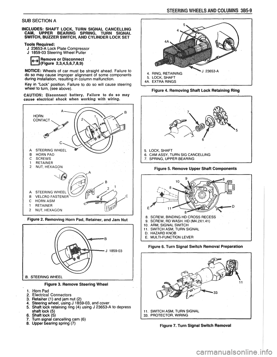
SUB SECTION A
INCLUDES: SHAR LOCK, TURN SIGNAL CANCELLING
CAM, UPPER BEARING SPRING, TURN SIGNAL
SWITCH,
BULZER SWITCH, AND CYLINDER LOCK SET
Tools Required:
J 23653-A Lock Plate Compressor
J 1859-03 Steering Wheel Puller
Remove or Disconnect
(Figure
2,3,4,5,6,7,8,9)
4 RING, RETAINING 5 LOCK, SHAFT
NOTICE: Wheels of car must be straight ahead. Failure to
do so may cause improper alignment of some components
during installation, resulting in column malfunction.
Key in "Lock position. Failure to do so will cause steering
- wheel to turn, (see above).
Figure 4. Removing Shaft Lock Retaining Ring
CAUTION: Disconnect battery. Failure to do so may
cause electrical
shock when working with wiring.
B HORN PAD
C SCREWS
1 RETAINER 2 NUT, HEXAGON
A STEERING WHEEL
B VELCRO FASTENE
C HORNASM
Figure 2. Removing Horn Pad, Retainer, and Jam Nut Figure
5. Remove Upper Shaft Components
8 SCREW,
BINDING HD CROSS RECESS 9. SCREW, RD WASH. HD (M4.2X1.41)
10 ARM, SIGNAL SWITCH
11 SWITCH ASM, TURN SIGNAL
D HAZARD KNOB
Figure 6. Turn Signal Switch Removal Preparation
Figure
3. Remove Steering Wheel
1. Horn Pad
2. Electrical Connectors 3. Retaiher (1) and jam nut (2) 4. Steering wheel, using J 1859-03, and cover 5. Shait lock retaining ring (4) using J 23653-A to depress
shaft lock (5)
6. Shaft lock (5) 7. Turn signal cancelling cam (6) 8. Upper bearing spring (7) Figure 7. Turn Signal Switch Removal
Page 161 of 1825
385.10 STEERING WHEELS AND COLUMNS
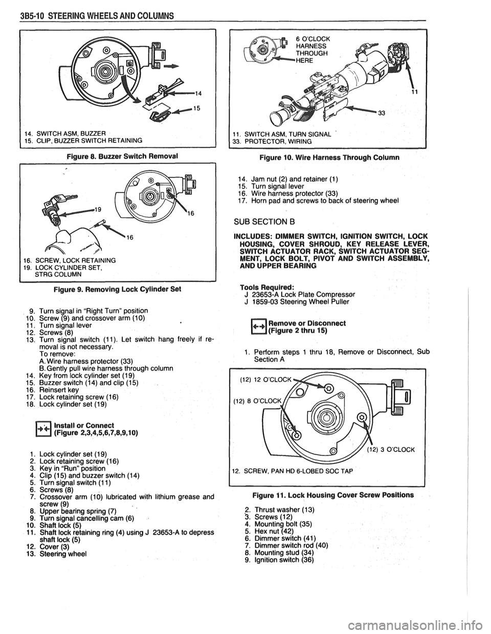
Figure 8. Buzzer Switch Removal
1 16. SCREW. LOCK RETAINING I 19. LOCK CYLINDER SET, I STRG COLUMN I
Figure 9. Removing Lock Cylinder Set
9. Turn signal in "Right Turn" position
10. Screw (9) and crossover arm (10)
11. Turn signal lever
12. Screws (8)
13. Turn signal switch (1 1). Let switch hang freely if re-
moval is not necessary.
To remove:
A. Wire harness protector (33)
6. Gently pull wire harness through column
14. Key from lock cylinder set (1 9)
15. Buzzer switch (1 4) and clip (1 5)
16. Reinsert key
17. Lock retaining screw (1 6)
18. Lock cylinder set (1 9)
Install or Connect
(Figure 2,3,4,5,6,7,8,9,10)
1. Lock cylinder set (1 9) 2. Lock retaining screw (1 6)
3. Key in "Run" position
4. Clip
(1 5) and buzzer switch (1 4)
5. Turn signal switch (1 1)
6. Screws (8)
7. Crossover arm (10) lubricated with lithium grease and
screw (9)
8. Upper bearing spring
(7) 9. Turn signal cancelling cam (6)
10. Shaft lock (5) 11. Shaft lock retaining ring (4) using J 23653-A to depress
shaft lock (5) 12. Cover (3) 13. Steering wheel
Figure 10. Wire Harness Through Column
14. Jam nut (2) and retainer (1)
15. Turn signal lever
16. Wire harness protector (33)
17. Horn pad and screws to back of steering wheel
SUB SECTION B
INCLUDES: DIMMER SWITCH, IGNITION SWITCH, LOCK
HOUSING, COVER SHROUD, KEY RELEASE LEVER,
SWITCH ACTUATOR RACK, SWITCH ACTUATOR SEG-
MENT, LOCK BOLT, PIVOT AND SWITCH ASSEMBLY,
AND UPPER BEARING
Tools Required:
J 23653-A Lock Plate Compressor J 1859-03 Steering Wheel Puller
++ Remove or Disconnect
(Figure 2 thru 15)
1. Perform steps 1 thru 18, Remove or Disconnect, Sub
Section A
(12) 12 O'CLOCK
12. SCREW, PAN HD
&LOBED SOC TAP
Figure 11. Lock Housing Cover Screw Positions
2. Thrust washer (1 3) 3. Screws (1 2)
4. Mounting bolt (35)
5. Hex nut (42)
6. Dimmer switch (41)
7. Dimmer switch rod (40)
8. Mounting stud (34)
9. Ignition switch (36)
Page 166 of 1825
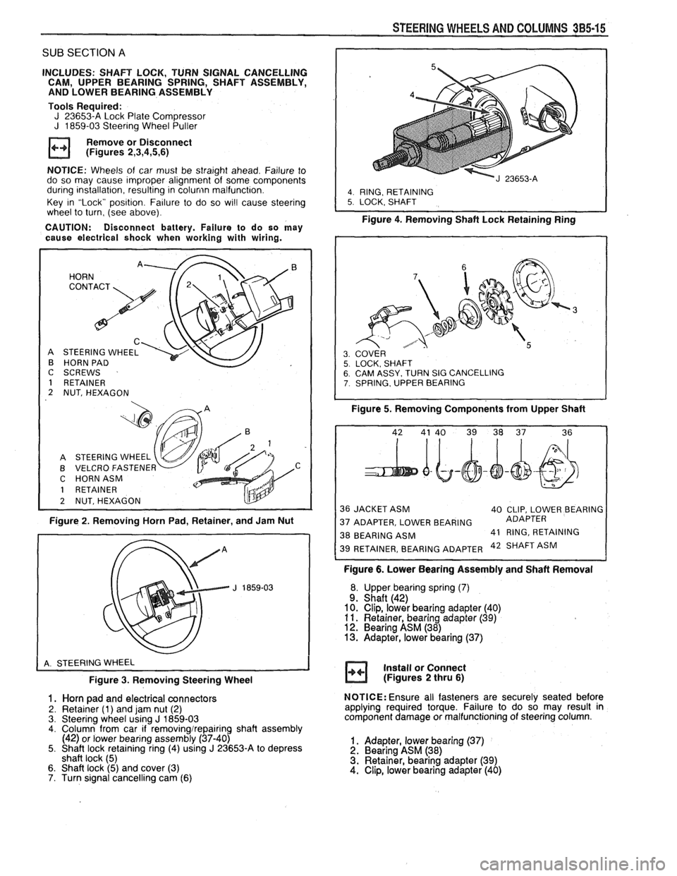
SUB SECTION A
INCLUDES: SHAFT LOCK, TURN SIGNAL CANCELLING
CAM, UPPER BEARING SPRING, SHAFT ASSEMBLY,
AND LOWER BEARING ASSEMBLY
Tools Required:
J 23653-A Lock Plate Compressor J 1859-03 Steering Wheel Puller
Remove or Disconnect
(Figures
2,3,4,5,6)
NOTICE: Wheels of car must be straight ahead. Failure to
do so may cause improper alignment of some components
during installation, resulting in
colunin malfunction.
Key in "Lock" position. Failure to do so
wi!l cause steering
wheel to turn, (see above).
CAUTION: Disconnect battery. Failure to do so may
cause electrical shock when working with wiring.
HORN
C
STEERING WHEEL
HORN PAD
I
C SCREWS
1 RETAINER
2 NUT, HEXAGON
A STEERING WHEEL
B VELCRO
FASTENEF v C HORNASM
1 RETAINER
2 NUTSHEXAGON
Figure 2. Removing Horn Pad, Retainer, and Jam Nut
Figure
3. Removing Steering Wheel
1. Horn pad and electrical connectors
2. Retainer (1) and jam nut (2)
3. Steering wheel using J 1859-03 4. Column from car if removingirepairing shaft assembly
(42) or lower bearing assembly (37-40)
5. Shaft lock retaining ring (4) using
J 23653-A to depress
shaft lock (5)
6. Shaft lock (5) and cover (3)
7. Turn signal cancelling cam (6)
STEERING WHEELS AND COLUMNS 385-15
I
4. RING, RETAINING 5. LOCK. SHAFT
Figure 4. Removing Shaft Lock Retainingain;
SY. TURN SIG CANCELLING , UPPER BEARING
Figure 5. Removing Components from Upper Shaft
36 JACKET ASM
40 CLIP, LOWER BEARING
37 ADAPTER, LOWER BEARING ADAPTER
38 BEARING
ASM 41
RING, RETAINING 42 SHAFT ASM
Figure 6. Lower Bearing Assembly and Shaft Removal
Upper bearing spring
(7) Shaft (42)
Clip, lower bearing adapter (40)
Retainer, bearing adapter
(39) Bearing ASM (38) Adapter, lower bearing (37)
Install or Connect
(Figures
2 thru 6)
NOTICE: Ensure all fasteners are securely seated before
applying required torque. Failure to do so may result in
component damage or malfunctioning of steering column.
1. Adapter, lower bearing (37) 2. Bearing ASM (38)
3. Retainer, bearing adapter (39)
4. Clip, lower bearing adapter (40)
Page 167 of 1825
385-16 STEERING WHEELS AND COLUMNS
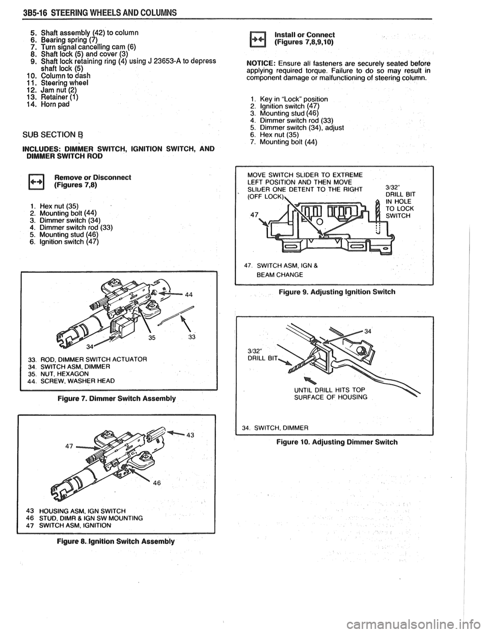
5. Shaft assembly (42) to column 6. Bearing spring (7)
7. Turn signal cancelling cam (6)
8. Shaft lock (5) and cover (3) 9. Shaft lock retaining ring (4) using J 23653-A to depress
shaft lock (5) 10. Column to dash 1 1. Steering wheel 12. Jam nut (2) 13. Retainer (1) 14. Horn pad
SUB SECTION Ej
INCLUDES: DIMMER SWITCH, IGNITION SWITCH, AND
DIMMER SWITCH ROD
Remove or Disconnect
(Figures
7,8)
1. Hex nut (35)
2. Mounting bolt (44)
3. Dimmer switch (34) 4. Dimmer switch rod (33)
5. Mounting stud (46)
6. lgnition switch (47)
Figure 7. Dimmer Switch Assembly
IGN SW MOUNTING
Figure 8. lgnition Switch Assembly install
or Connect
(Figures
7,8,9,10)
NOTICE: Ensure all fasteners are securely seated before
applying required torque. Failure to do so may result in
component damage or malfunctioning of steering column.
1. Key in "Lock" posit~sn 2. lgnltion switch (47)
3. Mounting stud (46)
4. Dimmer switch rod (33)
5. Dimmer switch (34), adjust 6. Hex nut (35) 7. Mounting bolt (44)
47 SWITCH ASM. IGN 8
Figure 9. Adjusting Ignition Switch
UNTIL DRILL HITS TOP
SURFACE OF HOUSING
34 SWITCH. DIMMER I
Figure 10. Adjusting Dimmer Switch