1988 PONTIAC FIERO horn
[x] Cancel search: hornPage 169 of 1825
385-18 STEERING WHEELS AND COLUMNS
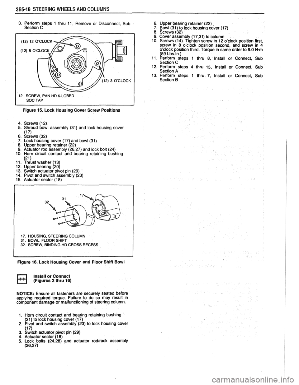
(12) 12 O'CLOCK
3. Perform steps 1 thru 11, Remove or Disconnect, Sub 6. Upper bearing retainer (22)
Section C 7. Bowl (31) to lock housing cover (17)
8. Screws (32)
9. Cover assembly (1
7,31) to column
10. Screws (14). Tighten screw in 12 o'clock position first,
screw in 8 o'clock position second, and screw in 4
o'clock position third. Torque in same order to 9.0
N.m (89 Lbs.ln.) 11. Perform steps 1 thru 8, Install or Connect, Sub
Section C 12. Perform steps 4 thru 15, Install or Connect, Sub
Section A
13. Perform steps 1 thru 7, Install or Connect, Sub
Section
B
Figure 15. Lock Housing Cover Screw Positions
4. Screws (12)
5. Shroud bowl assembly
(31) and lock housing cover 1171 6. ~c:dr'ews (32)
7. Lock housing cover (1 7) and bowl (31)
8. Upper bearing retainer (22)
9. Actuator rod assembly (26,27) and lock bolt (24)
10. Horn circuit contact and bearing retaining bushing
121 1 11. Yhiust washer (1 3) 12. Upper bearing (20)
13. Switch actuator pivot pin (29)
14. Pivot and switch assembly (23)
15. Actuator sector (1 8)
17. HOUSING, STEERING COLUMN 31. BOWL, FLOOR SHIFT 32. SCREW, BINDING HD CROSS RECESS
Figure 16. Lock Housing Cover and Floor Shin Bowl
Install
or Connect (Figures 2 thru 16)
NOTICE: Ensure all fasteners are securely seated before
applying required torque. Failure to do so may result in
component damage or malfunctioning of steering column.
1. Horn circuit contact and bearing retaining bushing
(21 ) to lock housing cover (1 7)
2. Pivot and switch assembly (23) to lock housing cover
(1 7) 3. Switch actuator pi~ot pin (29)
4. Actuator sector (1 8) 5. Lock bolts (2428) and actuator rodlrack assembly (26,271
Page 172 of 1825
STEERING WHEELS AND COLUMNS 385-21
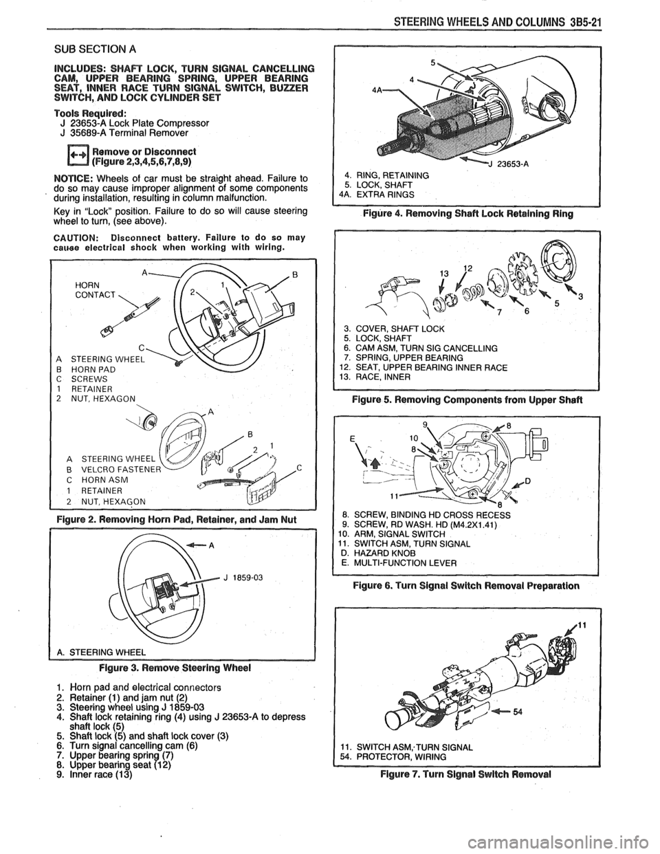
SUB SECTION A
INCLUDES: SHAR LOCK, TURN SIGNAL CANCELLING
CAM, UPPER BEARING SPRING, UPPER BEARING
SEAT, INNER RACE TURN SIGNAL SWITCH,
BUZER SWITCH, AND LOCK CYLINDER SET
Tools
Requird: J 236534 Lock Plate Compressor J 35689-A Terminal Remover
Remove or Disconnect
(Flgure 2,3,4,5,5,7,8,9)
NOTICE: Wheels of car must be straight ahead. Failure to
do so may cause improper alignment of some components
' during installation, resulting in column malfunction.
Key in "Lock" position. Failure to do so will cause steering
wheel
to turn, (see above).
CAUTION: Disconnect battery. Failure to do so may cauee electrical shock when working with wiring.
A STEERING WHEEL B HORN PAD
C SCREWS
1 RETAINER
2 NUT, HEXAGON
B VELCRO FASTENER C HORNASM
1 RETAINER
Figure 2. Removing Horn Pad, Retainer, and Jam Nut
Figure 3. Remove
Stwring Wheel
1. Worn pad and electrical connectors 2. Retainer (1) and jam nut (2) 3. Steering wheel using J 1859-03 4. Shaft lock retaining ring (4) using J 23653-A to depress
shaft lock (5) 5. Shaft lock (5) and shaft lock cover (3) 6. Turn signal cancelling cam (6) 7. Upper bearing sprin (7) 8. Upper bearing seat 71 2)
9. inner race (1 3)
Figure 4. Removing Shafl hock Retaining Ring
3. COVER, SHAFT LOCK 5. LOCK, SHAFT 6. CAM ASM, TURN SIG CANCELLING 7. SPRING, UPPER BEARING 12. SEAT, UPPER BEARING INNER RACE 13. RACE, INNER
Figure 5. Removing Components from Upper Shafl
ROSSRECESS
Figure 6. Turn Signal Swltch Removal Preparation
Figure
7. Turn Signal Switch Removal
Page 173 of 1825
385-22 STEERING WHEELS AND COLUMNS
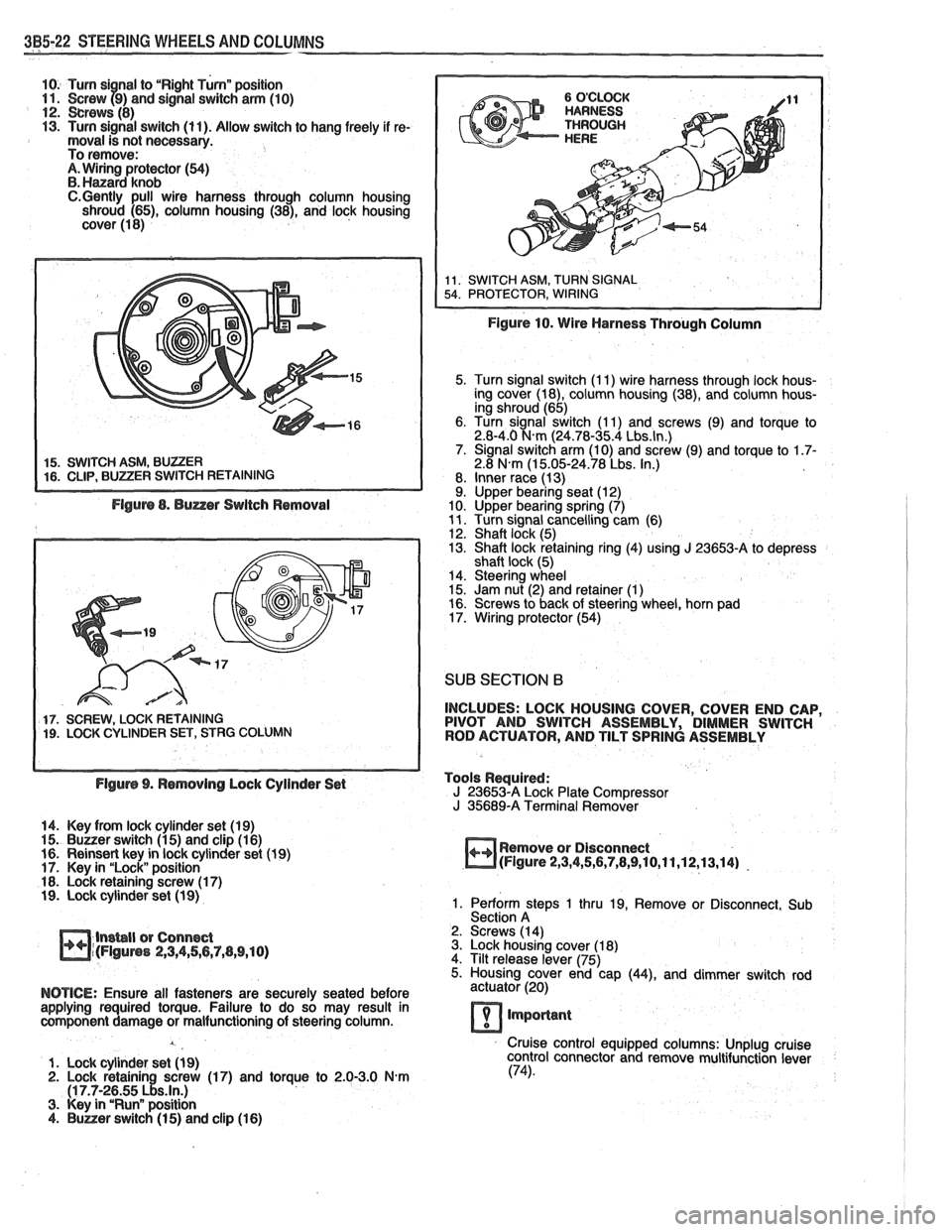
10. Turn si nal to "Right Turnn position 11. Screw f9) and signal switch arm (10) 12. crews (8) 13. Turn signal switch (11). Allow switch to hang freely if re- moval is not necessary.
To remove:
A. Wiring protector (54) B. Hanard knob C.Gently pull wire harness through column housing
shroud (65), column housing (38), and lock housing
cover (1 8)
5. Turn signal switch (I 1) wire harness through lock hous-
ing cover (18), column housing (38), and column hous-
ing shroud (65)
6. Turn signal switch (1 1) and screws (9) and torque to
2.8-4.0
N.m (24.78-35.4 Lbs.ln.) 7. Signal switch arm (10) and screw (9) and torque to 1.7- 2.8 N.m (1 5.05-24.78 Lbs. In.)
8. Inner race (13)
9. Upper bearing seat (12)
10. Upper bearing spring (7)
11. Turn signal cancelling cam (6)
12. Shaft lock (5)
13. Shaft lock retaining ring (4) using J 23653-A to depress
shaft lock (5)
14. Steering wheel
15. Jam nut (2) and retainer
(1) 16. Screws to back of steering wheel, horn pad
17. Wiring protector (54)
SUB SECTION 6
17. SCREW, LOCK RETAINING INCLUDES:
LOCK HOUSING COVER, COVER END CAP, 19. LOCK CYLINDER SET, STRG COLUMN PIVOT
AND SWITCH ASSEMBLY, DIMMER SWITCH
ROD ACTUATOR, AND TILT SPRING ASSEMBLY
Flgurs 9. Rsmovlng Lock Cylinder Set Tools
Required:
J 23653-A Lock Plate Compressor
J 35689-A Terminal Remover
14. Key from lock cylinder set (19)
15.
Buuer switch (1 5) and clip (1 6)
16. Reinsert key in lock cylinder set (1 9) Remove
or Disconnect
17. Key in "Lock" position
m(Flgure 2,3,4,5,6,7,8,9,10,11,12,13,14) -
18. Lock retaining screw (1 7) 19. Lock cylinder set (1 9) 1. Perform steps 1 thru 19, Remove or Disconnect, Sub
Section A
lnsbll or Connect 2.
Screws (14)
m~(FIguns 2,3,4,56,7,(1,9,10) 3. Lock housing cover (1 8)
4. Tilt release lever (75)
5. Housing cover end cap
(44), and dimmer switch rod
NOTICE: Ensure all fasteners are securely seated before actuator (20)
applying required torque. Failure to do so may result in
component damage or malfunctioning of steering column.
lmporlant
Cruise control equipped columns: Unplug cruise
1. Lock cylinder set
(1 9) control
connector and remove multifunction lever 2. Lock retainin screw (17) and torque to 2.0-3.0 N-m (74).
(1 7.7-2~55 ~!s.ln.) 3. Key in "Runn position 4. Buner switch (1 5) and clip (1 6)
Page 180 of 1825
STEERING WHEELS AND COLUMNS 3B5-29
SUB SECTION A
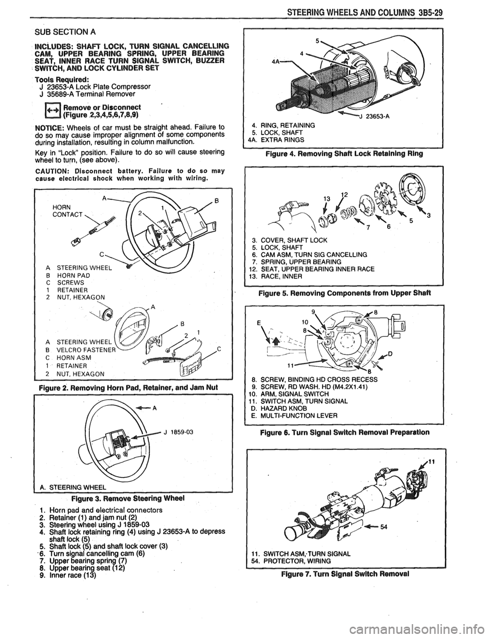
INCLUDES: SHAm LOCK, TURN SIGNAL CANCELLlNG CAM, UPPER BEARING SPRING, UPPER BEARING
SEAT, INNER RACE TURN SIGNAL SWITCH, BUZZER
SWITCH,
AND LOCK CYLINDER SET
Tools
Requird: J 23653-A Lock Plate Compressor J 35689-A Terminal Remover
Remove or Disconnect
(Figure
,2,3,4,5,6,7,8,9)
NOTICE: Wheels of car must be straight ahead. Failure to
do so may cause improper alignment of some components
during installation, resulting in column malfunction.
Key in
"Lock position. Failure to do so will cause steering
wheel to turn, (see above).
CAUTION: Disconnect battery. Failure to do so may
cause electrical shock when working with wiring.
HORN '. 72' CONTACT
A STEERING WHEEL
B HORN PAD C SCREWS 1 RETAINER 2 NUT, HEXAGON
A STEERING WHEEL
B VELCRO FASTENER C HORNASM
1 RETAINER
2 NUT, HEXAGON L!lY -
Figure 2. Removing Horn Pad, Retainer, and Jam Nut
Figure 3. Remove
Stwring Wheel
1. Horn pad and electrical connectors
2. Retainer (1) and jam nut (2) 3. Steering wheel using J 1859-03
4. Shaft lock retaining ring (4) using J 23653-A to depress
shaft lock (5)
5. Shaft lock (5) and shaft lock cover (3)
6. Turn signal cancelling cam (6)
7. Upper bearing sprin (7) 8. Upper bearing seat R 2) 9. Inner race (13)
4. RING, RETAINING
5. LOCK, SHAFT
4A. EXTRA RINGS
Figure 4. Removing Shafl Lock Retaining Ring
3. COVER, SHAm LOCK 5. LOCK, SHAFT 6. CAM ASM, TURN SIG CANCELLING 7. SPRING, UPPER BEARING
12. SEAT, UPPER BEARING INNER RACE
13. RACE, INNER
Figure 5. Removing Components from Upper Shan
Figure 6. Turn Signal Swltch Removal Preparation
11. SWITCH ASM;TURN SIGNAL 54. PROTECTOR, WIRING
Flgure 7. Turn Signal Switch Removal
Page 181 of 1825
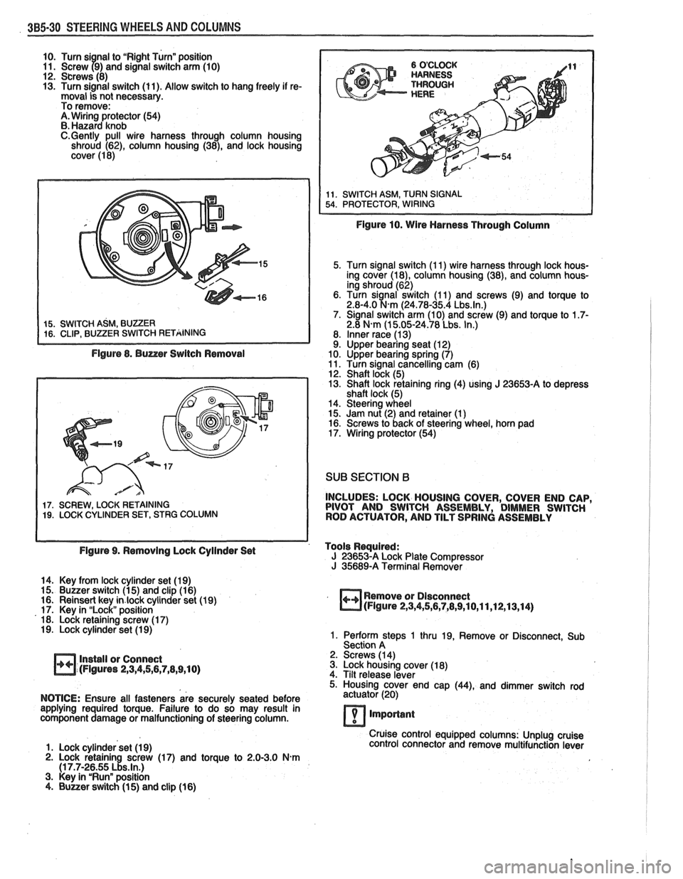
385-30 STEERING WHEELS AND COLUMNS
10. Turn si nal to "Right Turn" position
11. Screw 79) and signal switch arm (10)
12. Screws (8)
13. Turn signal switch (11). Allow switch to hang freely if re-
moval is not necessary.
To remove:
A. Wiring protector (54)
B. Hazard knob
C.Gently pull wire harness through column housing
shroud (62), column housing (38), and lock housing
cover (1 8)
Figure 8. Buzzer Switch Removal
17. SCREW, LOCK RETAINING 19. LOCK CYLINDER SET, STRG COLUMN
Figure 10. Wire Harness Through Column
5. Turn signal switch (1 1) wire harness through lock hous-
ing cover
(la), column housing (38), and column hous-
ing shroud (62)
6. Turn
sianal switch (1 1) and screws (9) and torque to 2.8-4.0 %km (24.78-35.4 Lbs.ln.) 7. Signal switch arm (10) and screw (9) and torque to 1.7- 2.8 N-m (1 5.05-24.78 Lbs. In.)
8. Inner race (1 3) 9. Upper bearing seat (1 2)
10. Upper bearing spring (7)
11. Turn signal cancelling cam (6)
12. Shaft lock (5)
13. Shaft lock retaining ring (4) using
J 23653-A to depress
shaft lock (5)
14. Steering wheel
15. Jam nut (2) and retainer (1
) 16. Screws to back of steering wheel, horn pad
17. Wiring protector (54)
SUB SECTION B
INCLUDES: LOCK HOUSING COVER, COVER END CAP,
PIVOT AND SWITCH ASSEMBLY, DIMMER SWITCH
ROD ACTUATOR, AND TILT SPRING ASSEMBLY
Figure 9. Removing Lock Cyilnder Set Tools
Rwuired: J 23653-A Lock
Plate Compressor J 35689-A Terminal Remover
14. Key from lock cylinder set (19)
15. Buzzer switch (1 5) and clip (1 6)
16. Reinsert key
in.lock cylinder set (19)
17. Key in "Lock" position
18. Lock retaining screw (1 7)
19. Lock cylinder set (1 9)
Install or Connect
(Figures
2,3,4,5,6,7,8,9,10)
Remove or Dlsconnect (Figure 2,3,4,5,6,7,8,9,10,11,12,13,14)
1. Perform steps 1 thru 19, Remove or Disconnect, Sub
Section A
2. Screws (1 4)
3. Lock housing cover (1 8)
4. Tilt release lever
5. Housing cover end cap
(44), and dimmer switch rod
NOTICE: Ensure all fasteners are securely seated before actuator
(20)
applying required torque. Failure to do so may result in
component damage or malfunctioning of steering column.
7 important
Cruise control equipped columns: Unplug cruise
1. Lock cylinder set (1 9) control
connector and remove multifunction lever
2. Lock retaining screw (17) and torque to 2.0-3.0 N.m (1 7.7-26.55 Lbs.ln.) 3. Key in "Run" position
4. Buuer switch (1 5) and clip (16)
Page 1166 of 1825
CONTENTS
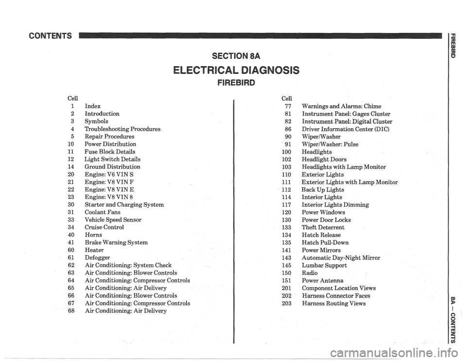
ELECTRICAL DIAGNOSIS
Cell
1
2
3
4 5
10
11
12 14
20
21
22
23
30
31
33
34
40
4
1
60
61
62
63
64
65
66
67
68
Index
Introduction
Symbols
Troubleshooting Procedures Repair Procedures
Power Distribution
Fuse Block Details
Light Switch Details
Ground Distribution
Engine:
V6 VIN S
Engine: V8 VIN
F
Engine: V8 VIN E
Engine:
V8 VIN 8
Starter and Charging System
Coolant Fans
Vehicle Speed Sensor
Cruise Control Horns
Brake Warning System
Heater
Defogger
Air Conditioning: System Check
Air Conditioning: Blower Controls
Air Conditioning: Compressor Controls
Air Conditioning: Air Delivery
Air Conditioning: Blower Controls
Air Conditioning: Compressor Controls
Air Conditioning: Air Delivery Cell
77
8
1
82
86 90
9
1
100
102
103
110
111
112
114
117
120
130
133
134
135
141
143
145
150
151
201 202
203
Warnings and Alarms: Chime
Instrument Panel: Gages Cluster
Instrument Panel:
Digital Cluster
Driver Information Center
(DIC)
WiperlWasher
WiperlWasher: Pulse
Headlights
Headlight Doors
Headlights with Lamp Monitor
Exterior Lights
Exterior Lights with Lamp Monitor
Back Up Lights
Interior Lights
Interior Lights Dimming
Power Windows
Power Door Locks
Theft Deterrent
Hatch Release
Hatch Pull-Down
Power Mirrors
Automatic Day-Night Mirror
Lumbar Support
Radio Power Antenna
Component Location Views
Harness Connector Faces
Harness Routing Views
Page 1167 of 1825
Page
Air Conditioning
Air Delivery
Electronic
.................... 68-0
Manual
....................... 65-0
Blower Controls
Electronic
.................... 66-0
Manual
....................... 63-0
Compressor Controls Electronic
.................... 67-0
Manual
....................... 64-0
................... System Check 62-0
Alarms (Audible)
Chime
......................... 77-0
Antenna(Power) ................... 151-0
Brakes
................. Warning System 41-0
................... Charging system 30-7
...................... Cigar Lighter 114-0
Circuit Breaker Details
PWR ACC Circuit
.......... Breaker 10.1.10.3.10.5.1 1.3
WDO Circuit Breaker
10.1. 10.3. 10.5. 11-4
.......... Component Location Views 201-0
Connectors (Harness Connector Faces) 202-0
el00 .......................... 202-0
............... Junction Block ((2238) 202-2
Coolant Fan
....................... 31-0
Cruise Control
..................... 34-0
Defogger
......................... 61-0
Digital Clock
...................... 150-0
Displays Digital Cluster
.................. 82-0
Coolant Temperature
........... 82-2
Page
......................... Fuel 82-3
................... Oil Pressure 82-2
.................. Speedometer 82-3
................. Door Locks (Power) 130-0
...... Driver Information Center (DIC) 86-0
Engines
... Multi-Port Fuel Injection (VIN S) 20-0
.... Multi-Port Fuel Injection (VIN 8) 23-0
.... Throttle
Body Injection (VIN E) 22-0
...... Tuned
Port Injection (VIN F) 21-0
................. Fuse Block Details 11-0
Fuse Details
........... INST LP 10.0.10.2.10.4.1 1.1
.............. TAIL 10.0.10.2.10.4.1 1.2
................ CRANK 10.0.10.2.1 0.4
.............. CTSY 10~0.10.2.10.4.1 1.2
......... STOP HAZ 10.1.10.3.10.5.1 1.3
............ RADIO 10.1.10.3.10.5.1 1.4
............ WIPER 10.1.10.3.10.5.1 1.4
.................... HATCH 10.2.1 0.4
........... HTR AlC 10.1.10.3.10.5.1 1.4
........... CIH.FAN 10.1.10.3.10.5.1 1.4
......... TURN BIU 10.1.10.3.10.5.1 1.4
............ GAGES 10.1.10.3.10.5.1 1.4
ECM-IGN
(V6 VIN S. V8 VIN F.
........ V8 VIN 8. V8 VIN E) 10.1.1 1.7
............ INJ 1 (V6 VIN S) 10.1.1 1.10
......... FPIINJ 2 (V6 VIN S) 10.1.1 1.10
... INJ 1 (V8 VIN F. V8 VIN 8) 10.3.1 1.11
FPIINJ 2 (V8 VIN F. V8 VIN 8) 10.3.1 1.11
............ CLSTR 10.1.10.3.10.5.1 1.13
............. FPIINJ 2 (V8 VIN E) 11-12
Page
Gages
................... Gages Cluster 81-0
........... Coolant Temperature 81-2
......................... Fuel 81-3
................... Oil Pressure 81-2
.................. Speedometer 81-3
................ Ground Distribution 14-0
Harness Routing Views
............. 203-0
........................... Heater 60-0
............................ Horns 40-0
Indicators
.................. Digital Cluster 82-0
................ Brake Warning 82-4
.................. Fasten Belts 82-1
...................... Hi Beam 82-1
...................... Security 82-1
............ Service Engine Soon 82-4
......................... Shift 82-5
......................... Turn 82-1
................... Gages Cluster 81-0
................ Brake Warning 81-0
.................. Fasten Belts 81-0
...................... Hi Beam 81-0
............ Service Engine Soon 81-0
......................... Shift 81-1
......................... Turn 81-0
Instrument Panel
Digital Cluster
.................. 82-0
Gages Cluster
................... 81-0
............ Interior Lights Dimming 117-0
...................... Introduction 2-0
Lights (Exterior)
........................ Back Up 112-0
...................... Fog 100.3,10 3.0
Page 1170 of 1825
These schematics break the entire electrical
system down into individual circuits. You are
not distracted by wiring which is not part of
the circuit you're working on.
It is important to realize that no attempt is
made on the schematic to represent compo-
nents and wiring as they physically appear on
the car. For example, a 4-foot length of wire is
treated no differently in a schematic from one
which is only a few inches long. The number of
cavities for each connector is listed in the Com-
ponent Location List. Similarly, switches and
other components are shown as simply as pos-
sible, with regard to function only.
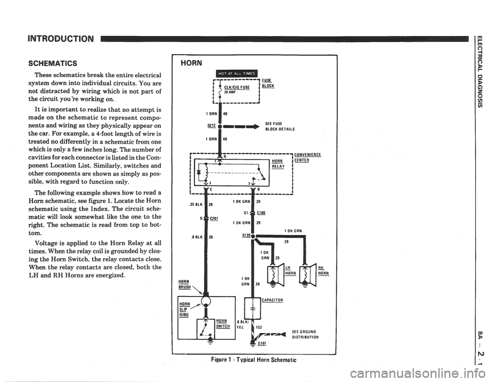
The following example shows how to read a
Worn schematic, see figure
1. Locate the Horn
schematic using the Index. The circuit sche-
matic will look somewhat like the one to the
right. The schematic is read from top to bot-
tom.
Voltage is applied to the Horn Relay at all
times. When the relay coil is grounded by clos-
ing the Horn Switch, the relay contacts close.
When the relay contacts are closed, both the
LH and
RH Horns are energized.
1 HORN
SEE FUSE
I BLOCK DETAILS
Figure 1 - Typical Horn Schematic