1988 PONTIAC FIERO ESP
[x] Cancel search: ESPPage 4 of 1825
GENERAL INFORMATION OA-1
SECTION (DA
GENERAL NFORMAT
CONTENTS
................................... General Description OA- 1 Prevailing Torque Fasteners ......................... OA-2
...................................... Body Number Plate OA- 1 Recommendations For Fastener Reuse ........ OA-2
..................... Vehicle Identification Number OA- 1 Vehicle Lifting Procedures ............ ., ............. OA-2
......................................... Metric Fasteners OA- 1 Precautions Against Tipping ........................ OA-7
................... Fastener Strength Identification OA-2 Automotive Abbreviations ................... .... 0.4- 1 1
GENERAL DESCRIPTION
Only general information appears in this section. left
of the windshield, see Figure 2. Refer to Figure 3
Detailed specifications on major units are given at the for detailed "VIN" code information.
For Engine V.I.
end of each respective section of this manual. N. Location, refer to Figure
4.
BODY NUMBER PLATE METRIC FASTENERS
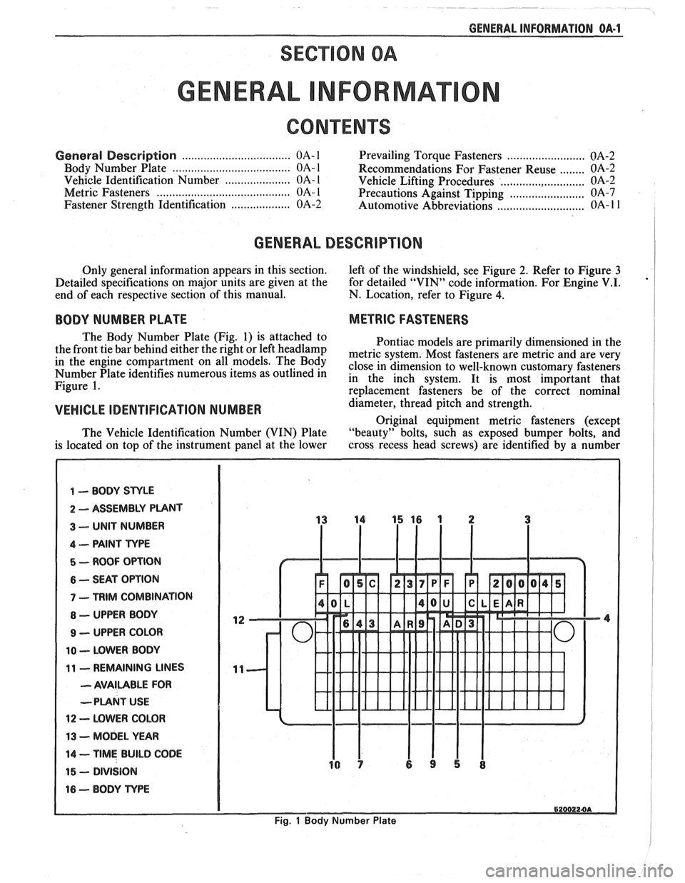
The Body Number Plate (Fig. 1) is attached to
Pontiac models are primarily dimensioned in the
the front tie bar behind either the right or left
headlamp metric system, Most fasteners are metric and are very in the engine On The close in dimension to well-known customary fasteners Number Plate identifies numerous items as outlined in in the inch system. It is most important that Figure 1. re~lacement fasteners be of the correct nominal
VEHICLE IDENTIFICATION NUMBER d&meter, thread pitch and strength.
Original equipment metric fasteners (except
The Vehicle Identification Number (VIN) Plate "beauty" bolts, such
as exposed bumper bolts, and
is located on top of the instrument panel at the lower cross
recess head screws) are identified by a number
1 -- BODY STYLE
2 ASSEMBLY PUNT
3 -- UNIT NUMBER
4 -- PAINT TYPE
5 - ROOF OPTION
6 -- SEAT OPTION
7 - TRIM COMBINATION
8 - UPPER BODY
9 - UPPER COLOR
10 -- LOWER BODY
11 - REMAINING LINES
- AVAILABLE FOR
--PLANT
USE
12 - LOWER COLOR
13 - MODEL YEAR
14 -- TIME BUILD CODE
15 - DIVISION
16 - BODY TvPE
6200224A
Fig. 1 Body Number Plate
Page 13 of 1825
OA-10 GENERAL INFORMATION
METRIC BOLT AND NUT IDENTIFICATION
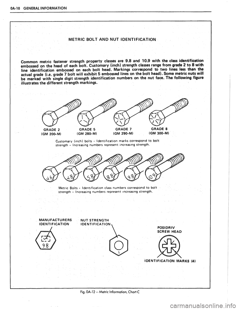
Common metric fastener strength property
classss are 9.8 and 10.9 with the clers idsntifica$ion
embossed on the haad of each bolt. Customary (inch) strength clases range from grade 2 to 8 wi(h
line ihntificaion embosssd on each bolt head. Markings correspond to two lines lsss than the
actual grade
(i.e. grade 7 bolt will exhibit 5 embossd lines on the bolt head). Some metric nuts will be markd with single digit strength identification numbers on the nut face. The following figure
illustr&es the different strength markings.
Customary (~nch) bolts - ldent~f~cat~on marks correspond to bolt
strength - lncreas~ng numbers represent lncreaslng strength.
Metr~c Bolts - ldent~f~cat~on class numbers correspond to bolt
strength - lncreas~ng numbers represent lncreaslng strength.
MANUFACTURERS NUT STRENGTH
IDENTIFICATION IDENTI FlCATlON
POSlDRlV
Fig. OA-12 -- Metric Information, Chart C
Page 55 of 1825
18-12 AIR CONDITIONING
ELEGTRICAWACUUM SYSTEM
DIAGNOSIS
When diagnosing problems in the electrical sys-
tems of the air conditioning system, consult section
8A.
LEAK TESTING THE REFRIGERANT
SYSTEM
Whenever a refrigerant leak is suspected in the
system or a service operation performed which results
in disturbing lines or connections, it is advisable to
test for leaks.
Liquid Leak Detectors
There are a number of locations (fittings,
valves, etc.) on the air conditioning system where a
liquid leak detector solution may be used to pinpoint
refrigerant leaks.
By applying test solution to the area in question
with the swab that is attached to the bottle cap, bub-
bles will form within seconds if there is a leak.
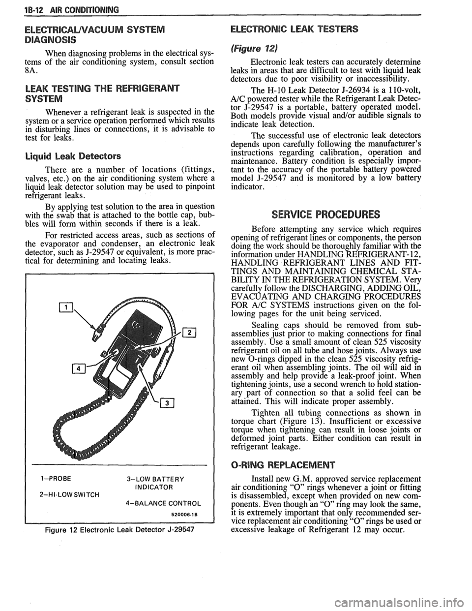
For restricted access areas, such as sections of
the evaporator and condenser, an electronic leak
detector, such as
5-29547 or equivalent, is more prac-
tical for determining and locating leaks.
3-LOW BATTERY
INDICATOR
2-HI-LOW SWITCH
4-BALANCE CONTROL
Figure 12 Electronic Leak Detector J-29547
ELECTRONIC LEAK TESTERS
(Figure 12)
Electronic leak testers can accurately determine
leaks in areas that are difficult to test with liquid leak
detectors due to poor visibility or inaccessibility.
The H-10 Leak Detector 5-26934 is a 110-volt,
A/C powered tester while the Refrigerant Leak Detec-
tor J-29547 is a portable, battery operated model.
Both models provide visual
and/or audible signals to
indicate leak detection.
The successful use of electronic leak detectors
depends upon carefully following the manufacturer's
instructions regarding calibration, operation and
maintenance. Battery condition is especially impor-
tant to the accuracy of the portable battery powered
model
5-29547 and is monitored by a low battery
indicator.
SERVICE PROCEDURES
Before attempting any service which requires
opening of refrigerant lines or components, the person
doing the work should be thoroughly familiar with the
information under HANDLING REFRIGERANT- 12,
HANDLING REFRIGERANT LINES AND FIT-
TINGS AND MAINTAINING CHEMICAL STA-
BILITY IN THE REFRIGERATION SYSTEM. Very
carefully follow the DISCHARGING, ADDING OIL,
EVACUATING AND CHARGING PROCEDURES
FOR
A/C SYSTEMS instructions given on the fol-
lowing pages for the unit being serviced.
Sealing caps should be removed from sub-
assemblies just prior to making connections for final
assembly. Use a small amount of clean 525 viscosity
refrigerant oil on all tube and hose joints. Always use
new O-rings dipped in the clean 525 viscosity refrig-
erant oil when assembling joints. The oil will aid in
assembly and help provide a leak-proof joint. When
tightening joints, use a second wrench to hold station-
ary part of connection so that
a solid feel can be
attained. This will indicate proper assembly.
Tighten all tubing connections as shown in
torque chart (Figure
13). Insufficient or excessive
torque when tightening can result in loose joints or
deformed joint parts. Either condition can result in
refrigerant leakage.
O-RING REPWCEMENT
Install new G. M. approved service replacement
air conditioning
"0" rings whenever a joint or fitting
is disassembled, except when provided on new com-
ponents. Even though an
"0" ring may look the same,
it is extremely important that only recommended ser-
vice replacement air conditioning
"0" rings be used or
excessive leakage of Refrigerant 12 may occur.
Page 98 of 1825
R-4 818 CONDITIONING COMPRESSOR OVERHAUL 1D1-19
retainers are to be removed, remove two sets and
then rotate compressor and Holding Fixture
J-25008-A in vise for access to the remaining two
valve plates and retainers.
Install or Connect
1. Install Discharge Valve Plates and/or Retainers.
Reposition compressor and Holding Fixture in
vise as necessary for access.
Valve plates must
be tight
following retainer assembly.
2. Reinstall compressor Shell as described in
SHELL AND O-RINGS replacement
procedures.
3. Evacuate and charge the refrigerant system
according to the directions in Section
1B.
CYLINDER AND SHAFT ASSSEMBLY
Remove or Disconnect
Discharge the refrigerant system according to the
directions in Section
1B.
Remove the Clutch Plate and Hub assembly as
described in CLUTCH PLATE AND HUB
removal procedure.
Perform Steps
1 through 4 of CLUTCH ROTOR
AND BEARING removal procedure but do not
loosen or remove the pulley rim mounting screws.
Remove the Clutch Rotor and Bearing, Clutch
Coil and Pulley Rim as an assembly. Be careful
not to drop the Puller Guide J-25031, when
removing the assembly.
Remove the shaft seal as described in SHAFT
SEAL removal procedure.
Remove the front head as described in FRONT
HEAD REMOVAL procedure.
Remove the thrust and belleville washers as
described in THRUST AND BELLEVILLE
WASHERS removal procedures.
Remove the compressor shell as described in
SHELL removal procedure.
Remove the discharge valve plate and retainer as
described in DISCHARGE VALVE PLATE
AND RETAINER removal procedure.
Remove the high pressure relief valve as
described in
HIGH PRESSURE RELIEF
VALVE REMOVAL PROCEDURE.
L
Install or Connect
1. Replace above parts in opposite order.
2. Evacuate and charge the refrigerant system
according to the directions in Section
1B.
LEAK TESVING (EXTERNAL AND INTERNAL)
Bench-Check Procedure
1. Install Test Plate J-9625-A on Rear Head of
compressor.
2. Attach center hose of Manifold Gage Set on
Charging Station to a refrigerant drum standing
in an upright position and open valve on drum.
3. Connect Charging Station high and low pressure
lines to corresponding fittings on Test Plate J-9625-A, using
5-5420 Gage
Adapters if hoses
are not equipped with valve depressors.
Suction port (low-side) of compressor has
large internal opening. Discharge port
(hi-side) has smaller internal opening into
compressor.
Open low-pressure control, high-pressure control
and refrigerant control on Charging Station to
allow refrigerant vapor to flow into compressor.
Using a Leak Detector, check for leaks at
Pressure Relief Valve, compressor shell to
cylinder, compressor front head seal, and
compressor Shaft Seal. After checking, shut off
low pressure control and high pressure control on
Charging Station.
If an external leak is present, perform the
necessary corrective measures and recheck for
leaks to make certain the leak has been corrected.
Loosen the Manifold Gage hose connections to
the Gage Adapters J-5420 connected to the low
and high sides and allow the vapor pressure to
release from the compressor.
Disconnect both Gage Adapters
5-5420 from the
Test Plate J-9625-A.
Rotate the complete compressor assembly (not
the crankshaft or drive plate hub) slowly several
turns to distribute oil to all cylinder and piston
areas.
Install a shaft nut on the compressor crankshaft
if the drive plate and clutch assembly are not
installed.
Using a box-end wrench or socket and handle,
rotate the compressor crankshaft or clutch drive
plate on the crankshaft several turns to ensure
piston assembly to cylinder wall lubrication.
Connect the Charging Station high pressure line
or a high pressure gage and Gage Adapter J-5420
to the Test Plate J-9625-A high side connector.
Attach an Adapter
9-5420 to the suction or low
pressure port of the Test Plate
J-9625-19 to open
the Schrader-type valve.
Oil will drain out of the compressor suction port
adapter if the compressor is positioned with the
suction port downward.
Attach the compressor to the Holding Fixture
J-25008-A using metric mounting screws. Clamp
the compressor Holding Fixture in a vise so that
the compressor can be manually turned with a
wrench.
Using a wrench, rotate the compressor crankshaft
or drive plate hub ten complete revolutions at a
speed of approximately one-revolution per
second.
Turning the compressor at less than
one-revolution per second can result in a lower
pump-up pressure and disqualify a good pumping
compressor.
Observe the reading on HIGH pressure gage at
the completion of the tenth revolution of the
compressor. The pressure reading for a good
pumping compressor should be 344.75
kPa (50 p.
s.i.) or above. A pressure reading of less than 3 10.
275 kPa (45 p.s.i.) would indicate one or more
Page 111 of 1825
2C-4 CHASSIS SHEET METAL
3. Clean area to be repaired.
4. Mix and apply the repair material by using a
putty knife or rubber squeegee.
5. Work the material into the repair and build up
the desired contour. For deep filling, and on
vertical surfaces, several layers may be
required.
6. Feather-sand damaged area with No. 200 sand-
paper and finish-sand with No. 320 sandpaper.
7. Prepare repaired area for refinishing. Refinish
with acrylic lacquer as described below.
1. THOROUGHLY CLEAN the entire surface
area, using Naphtha or equivalent solvent, to
insure a surface free of contamination.
2. To promote paint adhesion, a light scuff-sand-
ing of the surface with
#400-grit sandpaper is
recommended.
3. Repeat cleaning of the surface.
4. Color coat with acrylic lacquer for proper color
match.
5. Allow to dry thoroughly, rub out and polish.
PAINT REFINISHING PROCEDURES FOR
URETHANE, P.V.C. AND T.P.R. SURFACES
Urethane material will withstand minor impact
and the resultant damage, such as occurs in parking
lots, by recovering its original shape. Its Endura paint
film responds to impact in a similar manner without
cracking or splitting. If, however, an area of damage
in the Urethane bumper or panel does not recover its
shape, or the surface is punctured, gouged or torn, a
repair system has been developed to restore the origi-
nal shape and appearance of the urethane-base
material.
CALSVON: There are a number of paint
systems available For service use; how-
ever,
many require additives containing
isocyanates.
It is essential that all rec-
ommendations and warnings listed on
the container label for
materials
seleded be followed.
CAUTION: If the paint system selected
specifies an additive containing
isocya-
nates, it is mandatory that adequate
respiratory protection be worn. An
example of such protection
is an air line
respirator with a
full hood or half mask.
If not
avaiable, use a vaporlpaHiculate
respirator that the respirator supplier
recommends as
efFective for isocyanate
vapors and mists (unless local
regula-
tions prevail).
Such protection should be worn during the
entire painting process. Persons with respiratory
problems, or those
allergic to isocyanates must not
be exposed to isocyanate vapors or spray mist.
REPAIRING & REFINISHING URETHANE
BUMPERS AND FRONT END PANELS
Required Materials:
1. 3M No. 8101 Structural Adhesive, or
equivalent.
2. Color Coat - Dexlar (DuPont) Flexible Finish
Enamel Color Coat, or Ditzler Elastomeric
Enamel Color Coat or equivalent.
3. Additive
- DuPont 792s Centari Hardener,
or
Ditzler
DXR-80 Delthane Additive or
equivalent.
4. Thinner
- DuPont 3608s Acrylic
Lacquer
Thinner, or Ditzler Delstar DTR 601 Acrylic
Enamel Reducer or equivalent.
NOTICE: Use the same brand name materials for
the color coat, additive, and thinner.
5. A wax and adhesive cleaner.
Equipment Needed:
1. Wooden spatula (enclosed in repair package).
2. Heat lamp.
3. 36 grit 180-A, 240-A, and 320-A grit disc
sandpaper.
4. Random orbital-type sander.
5. Body repair tape.
6. Suction spray gun (same nozzle and air cap
combination as used for acrylic).
Repair Procedure
There are three types of repairable damage on
urethane material. They are a puncture, a gouge and a
tear.
Following is the basic repair procedure for
repairing these types of damages.
1. Clean the damaged area with 3M #8984 Gen-
eral Purpose Adhesive Cleaner or equivalent. If
the damage is through the thickness of the part,
clean both sides.
Grind away damaged material with a
36 grit
disc. Feather edge the paint around the damage
using a
1808 grit disc.
2. If the part has a puncture or tear, file or rout out
the area where joint line will be. Bevel the edge
of the part with the open edge towards the side
to be filled (fill from the side with easiest
access). Clean the repair area with a clean dry
rag.
3. Apply 3M #6935 Auto Body Repair Tape, or
equivalent, to the underside of the repair area to
backup the repair material.
NOTICE: Before going to the next step, be sure
all of the paint (both topcoat and primer) has been
removed from the area where the structural adhe-
sive is to be applied.
Page 128 of 1825
STEERING, SUSPENSION, VIBES AND WHEELS DIAGNOSIS 3-3
Steering Wheel Kick-Back (Power)
Inspect
e Air in system
e Loose steering gear mounting
e Joints from column to steering gear loose or worn
e Tie rod ends loose
Worn or missing check valve
(800 series)
e Wheel bearings worn
e See "Too Much Play In Steering" for other
possible causes.
Steering Wheel Surges Or Jerks (Power)
Inspect
Hydraulic system - Make pressure test with gage
J 5176-D or
J 25323
e Sluggish steering gear valve
Loose pump drive belt
Cupped Tires
Inspect
Front-wheel or rear-wheel alignment
e Strut dampeners or shock absorbers weak
e Wheel bearing worn
e Excessive tire or wheel runout
e Worn ball joint
a Loose steering gear adjustment
POWER RECIRCULATING BALL
SEERING GEAR DIAGNOSIS
Hissing Noise
There is some noise in all power steering systems.
One of the most common is a hissing sound when the
steering wheel is turned and the car is not moving. This
noise will be most evident when turning the wheel
while the brakes are applied. There is no relationship
between this noise and steering performance. Do not
replace the valve unless the "hissing" noise is extremely
objectionable. A replacement valve will also have a
slight noise, and is not always a cure for the condition.
Check that the intermediate shaft joints are not loose.
Rattle or Chucking Noise
Inspect -
Pressure hose grounding out
e Tie rod ends loose
e Steering gear attachment loose
a Loose pitman shaft "over-center" adjustment.
A slight rattle may occur on turns because of
increased clearance off the "high point". This is
normal and clearance must not be reduced below
specified limits to eliminate this slight rattle.
Poor Return of Steering Wheel to Center
Front-wheel alignment
Wheel bearing worn
Tie rod end binding
Ball joint binding
Steering wheel rubbing against turn signal
housing
Steering gear adjustments
Tight or frozen intermediate steering shaft
Sticky or plugged spool valve
Momentary Increase in Effort Whsn Turning
Wheel Fast to Right or Left
Inspect
High internal leakage
Steering Wheel Surges or Jerks When Turning
With
Engine Running Especially During Parking
ln8pe~t
e Insufficient pump pressure
Sticky flow control valve
Excessive Wheel Kickback or Loose Steering
Air in system
Steering gear attachment loose
Tie rod ends loose
Wheel bearings worn
Steering gear flexible coupling loose on shaft or
rubber disc mounting nuts loose
Loose thrust bearing preload adjustment
Excessive "over-center" lash
Worn pressure port check valve
Hard Steering or Lack of Assist
(Especially During Parking)
-
Brakes applied while turning steering wheel
Intermediate shaft damaged or worn
e Sticky flow control valve
Insufficient pump pressure
Excessive internal pump leakage
Excessive internal steering gear leakage
STEERING LINKAGE DIAGNOSIS
Excessive Play or Looseness in Steering Systern
inspect
r, Worn upper ball joints
e Steering gear worm bearings loosely adjusted
Page 135 of 1825

3-10 STEERING, SUSPENSION, TIRES AND WHEELS DIAGNOSIS
Reminder Keeps Operating With Key In Lock
Cylinder, Driver's Door Open Or Closed; Ceases
When Key Is Removed
Inspect
s Door jamb switch on driver's side misadjusted or
inoperative.
e Wire from signal switch to door jamb switch
shorted.
A. This condition indicates the lock cylinder or
the reminder switch is at fault. To verify,
check for continuity at the
"E" and "F"
male column connector contacts, with the
key removed from the lock cylinder. If
continuity exists, the fault is in the column.
B. Insert the key into the lock, then turn the
lock toward the "Start" position. If the
reminder stops when the key is in the
"Run" position or when it is turned past
"Run" toward "Start," the problem is a
sticky lock cylinder actuator.
COLUMN-MOUNTED DIMMER SWITCH
No "Low" or "High" Beam
Inspect
e Loose connector at dimmer switch
e Improper adjustment
e Internally damaged or worn switch. Check the
continuity on the switch at the It. green and at the
tan switch terminals by pushing in the plunger all
the way.
A click should be heard. If there is no
continuity, replace the dimmer switch. If there is
continuity, refer
to'section 8A for electricaldiag-
nosis.
PIVOT AND SWITCH ASSEMBLY
Switch Inoperative: No "Low," "High" and/or
"Wash"
e Loose body-to-switch connector
a Broken or damaged switch
Internally damaged or worn switch. Connect a
new switch without removing the old one. If the
system functions, replace the switch. If the
system doesn't function, refer to Section
8A for
electrical diagnosis.
STEERING GEAR AND PUMP LEAKS
General Procedure
Inspect
s Overfilled reservoir
s Fluid aeration and overflow
e , Hose connections
Verify exact point of leakage Example:
Torsion bar, stub shaft and
adjuster seals are close together; the exact
spot where the system is leaking may not be
clear.
Example: The point from which the fluid is
dripping is not necessarily the point where
the system is leaking; fluid overflowing from
the reservoir, for instance.
e When service is required:
A. Clean leakage area upon disassembly.
B. Replace leaking seal.
C. Check component sealing surfaces for
damage.
D. Reset bolt torque to specifications, where
required.
Some complaints about the power steering system
may be reported as:
A. Fluid leakage on garage floor
B. Fluid leaks visible on steering gear or pump
C. Growling noise, especially when parking or
when engine is cold
D. Loss of power steering when parking
E. Heavy steering effort
When troubleshooting these kinds of complaints,
check for an external leak in the power steering system.
For further diagnosis of leaks, refer to External
Leakage Check in this section.
External Leakage Check
Fig. 12
The purpose of this procedure is to pinpoint the
location of the leak.
In some cases, the leak can easily be located. But,
seepage-type leaks may be more difficult to isolate. To
locate seepage leaks, use the following method.
1. With the engine off, wipe dry the complete power
steering system.
2. Check the fluid level in the pump's reservoir. Add
fluid if necessary.
3. Start the engine, then turn the steering wheel
from stop to stop several times. Do not hold it at
a stop for any length of time, as this can damage
the power steering pump. It is easier if someone
else operates the steering wheel while you search
for the seepage.
4. Find the exact area of the leak and repair leak.
SEAL REPLACEMENT
RECOMMENDATIONS
Lip seals, which seal rotating shafts, require
special treatment. This type of seal is used on the
steering gear and on the drive shaft of the pump. When
there is a leak in one of these areas, always replace the
seal(s), after inspecting and thoroughly cleaning the
sealing surfaces. Replace the shaft only if very severe
pitting is found. If the corrosion in the lip seal contact
zone is slight, clean the surface of the shaft with crocus
cloth. Replace the shaft only if the leakage cannot be
stopped by first smoothing with crocus cloth.
Page 143 of 1825
3-18 STEERING, SUSPENSION, TIRES AND WHEELS DIAGNOSIS
VIBRATION COMPLANT TIRE-WHEEL-HUB-AXLE RELATED
Vibrations that are tire or wheel induced can be caused
by two factors: imbalance or
runout. Low-speed vibrations, those less than 40 mph, are
usually runout related. Highway speed vibrations, those
above 40 mph, can be caused by either imbalance or runout. Prior to performing any work, always road test the car
and perform a careful visual inspection for:
- Obvious tire and wheel runout. - Obvious drive 'axle or propeller shaft runout. - Proper inflation pressure. - Wrong trim height. - Bent wheels. - Debris build-up on the tire or wheel. - Loose or missing wheel weights or wheel nuts. - Irregular or excessive tire wear. - Proper tire bead seating on rim. - Damaged tires, such as tread distortions,
separations, or bulges from impact damage. Slight sidewall indentations are normal and will not affect
ride quality.
Balance is the easiest procedure to perform and should,
therefore, be done fist if the vibration occurs at highway
speeds.
An off-car two-plane dynamic balance should first
be performed. This will correct any imbalance in the tire and
wheel assembly.
An oncar fiish balance may also be required. This will correct any brake drum, rotor, or wheel cover imbalance.
Follow the balancing procedures outlined in Section 3E. If balance does not correct the highway speed vibration,
or if the vibration is at low speeds, runout is the probable
cause. Runout can be caused by the tire, wheel, or the way
the wheel attaches to the car. The following procedure
should be used
: A. If runout is suspected, the free runout of the tire
and wheel assembly should first be measured on the car. A
dial indicator with a roller wheel is preferable, but a dial
indicator with button end may be used. Lateral
runout (side
to side) should be measured on the tire's sidewall as close to
the tread shoulder as possible. Radial
runout (up and down)
should be measured on the center tread rib. Some tread
designs may require tightly wrapping a piece of tape around
the center tread circumference for better dial indicator
contact. For measuring wheel
runout follow the "Measuring
Wheel Runout" procedure in Section 3E. Whether measuring
radial or lateral runout, disregard any instantaneous indicator
needle jumps due to sidewall depressions, tread blocks, etc.
Record the total indicator reading, and the location of the
high point of
runout. The,,total tire and wheel oncar runout should be less than ,060 , if either measurement exceeds ,060"~ proceed to Step B.
B. If
the oncy radial or lateral runout measured in
Step A exceeds .060 , mount the tire and wheel assembly on
a dynamic balance machine and again measure the amount of runout. Locate on the machine by the wheel's inside center
pilot hole. Using the same procedure as in Step A, record the
amount of tire and wheel
runout and its high point Location.
Next, measure wheel runout, see Section 3E. If the wheel
exceeds specifications replace the ~heel.,~If the tire and wheel
radial or lateral runout exceeds .050 at the tire tread,
proceed to Step C.
C. If the off-car tire and wheel radial or lateral runout measured in Step 18 exceeds .050", match mount the high radial runout point of tire to low radial runout point of
wheel. Weinflate, mount on the dynamic balance machine,
and again measure and record the radial and lateral runout and its location, as done in Step B. In many cases, match
mounting the tire on the wheel will bring the assembly's
runout into the acceptable range of less than .050". D. If the runout of the tire and wheel assembly is
within limits when measured off the car, yet exceeds the
limits when measured on the car, the attachment of the tire
and wheel assembly to the hub is the probable cause. Rotate
the assembly two wheel studs and recheck the
runout. Several positions may have to be tried to find the best
location.
E. If the assembly runout cannot be reduced to an
acceptable level, remove the tire and wheel assembly and
measure wheel stud
runout with a dial indicator. Zero
the dial indicator button on one stud. Lift button gently
off stud and rotate flange to position next stud against
dial indicator button. Record the
runout on all studs. Dial indicator should read zero when repositioned on first stud
that was checked. If runout exceeds .030", the hub or axle
shaft should be replaced.
Whenever a tire is rotated on the wheel, or a tire or
wheel is replaced, the assembly must be rebalanced.
In addition to balance and tire and wheel free
runout, tire stiffness variation (loaded radial runout) can also cause
a vibration. However, this is impossible to measure without
a TPD (Tire Problem Detector) or a loaded radial
runout buffer.
The TPD is a roller drum that slowly rotates the tire
while under load and mounted on the car. Tire stiffness
variation causes wheel spindle movement which can be
measured.
The loaded radial
runout buffer is a more automated
machine that slowly rotates the tire and wheel off the car
under load with a roller drum and measures the tire's
stiffness variation. It will then "match" the tire to the wheel
by buffing off small amounts of rubber from the outer tread
rows at the stiff spot. This procedure is usually effective,
especially when used
as a measuring device and for fine
buffing only.
The
TPD and loaded radial runout buffer are two
methods that will measure or correct tire stiffness variation,
tire
runout, and wheel runout at the same time. However,
because such equipment is not always available, and both
have their disadvantages, the more basic procedure of
measuring free
runout with a dial indicator, as previously
detailed, is usually more practical. The free runout of the
tire will usually correspond with the tire's stiff spot.
The substitution method of vibration diagnosis can also
be used. Install
a known good set of tire and wheel
assemblies. If these correct the vibration, the original
assemblies should be reinstalled one at
a time until the
vibration returns. This will point out the tire with excess
stiffness variation.
Tire stiffness variation will be higher or lower depending
on the direction of tire rotation.
Fig. 20 Vibration Complaint Chart (2 of 2)