1988 PONTIAC FIERO ESP
[x] Cancel search: ESPPage 286 of 1825
REAR AXLE 48-13
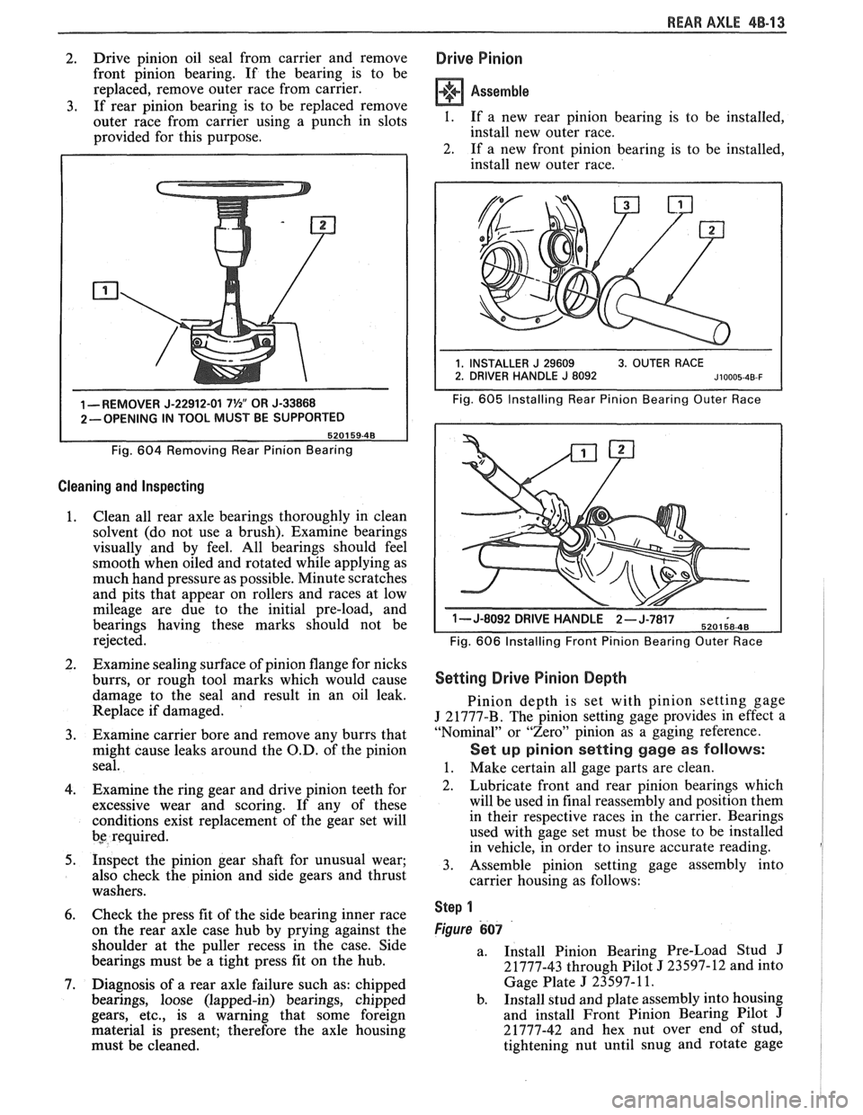
2. Drive
pinion oil seal from carrier and remove
front pinion bearing. If the bearing is to be
replaced, remove outer race from carrier.
3. If rear pinion bearing is to be replaced remove
outer race from carrier using a punch in slots
provided for this purpose.
1 -REMOVER J-22912-01 7%" OR J-33868
2-OPENING IN TOOL MUST BE SUPPORTED
Fig.
604 Removing Rear Pinion Bearing
Cleaning and Inspecting
1. Clean
all rear axle bearings thoroughly in clean
solvent (do not use a brush). Examine bearings
visually and by feel. All bearings should feel
smooth when oiled and rotated while applying as
much hand pressure as possible. Minute scratches
and pits that appear on rollers and races at low
mileage are due to the initial pre-load, and
bearings having these marks should not be
rejected.
2. Examine sealing surface of pinion flange for nicks
burrs, or rough tool marks which would cause
damage to the seal and result in an oil leak.
Replace if damaged.
'
3. Examine carrier bore and remove any burrs that
might cause leaks around the O.D. of the pinion
seal.
4. Examine the ring gear and drive pinion teeth for
excessive wear and scoring. If any of these
conditions exist replacement of the gear set will
bs required.
5. Inspect the pinion gear shaft for unusual wear;
also check the pinion and side gears and thrust
washers.
6. Check the press fit of the side bearing inner race
on the rear axle case hub by prying against the
shoulder at the puller recess in the case. Side
bearings must be a tight press fit on the hub.
7. Diagnosis of a rear axle failure such as: chipped
bearings, loose (lapped-in) bearings, chipped
gears, etc., is a warning that some foreign
material is present; therefore the axle housing
must be cleaned.
Drive Pinion
Assemble
I. If a new rear pinion bearing is to be installed,
install new outer race.
2. If a new front pinion bearing is to be installed,
install new outer race.
Fig. 605 Installing Rear Pinion Bearing Outer Race
1- J-8092 DRIVE H-,.wb- 6
Fig. 606 Installing Front Pinion Bearing Outer Race
Setting Drive Pinion Depth
Pinion depth is set with pinion setting gage
J 21777-B. The pinion setting gage provides in effect a
"Nominal" or "Zero" pinion as a gaging reference.
Set up pinion setting gage as follows:
1. Make certain all gage parts are clean.
2. Lubricate front and rear pinion bearings which
will be used in final reassembly and position them
in their respective races in the carrier. Bearings
used with gage set must be those to be installed
in vehicle, in order to insure accurate reading.
3. Assemble pinion setting gage assembly into
carrier housing as follows:
Step 1
Figure 607
a.
Install Pinion Bearing Pre-Load Stud J
21777-43 through Pilot J 23597-12 and into
Gage Plate
J 23597- 11.
b. Install stud and plate assembly into housing
and install Front Pinion Bearing Pilot
J
21777-42 and hex nut over end of stud,
tightening nut until snug and rotate gage
Page 290 of 1825
REAR AXLE 48-1 7
approached. No further tightening should be
attempted until the pre-load has been checked.
7. Check pre-load by using an inch pound torque
wrench.
NOTICE: After pre-load has been checked, final
tightening should be done very carefully. For
example, if when checking, pre-load was found to
be 0.6
N-m (5 lbs. in.), any additional tightening
of the pinion nut can add many additional pound
inch of torque. Therefore, the pinion nut should be
further tightened only a little at a time and the
pre-load should be checked after each slight
amount of tightening. Exceeding pre-load
specifications will compress the collapsible spacer
too far and require the installation of a new
collapsible spacer.
While observing the preceeding note, carefully set
pre-load at 2.7 to 3.6
N-m (24 to 32 1b.in.) on new
bearings or 1.0 to 1.4
N m (8 to 12 1b.in.) on used
bearings.
8. Rotate pinion several times to assure that
bearings have been seated. Check pre-load again.
If pre-load has been reduced by rotating pinion,
reset pre-load to specifications.
Rear Axle Backlash Adjustment
1. Install rear axle case into carrier, using shims as
determined by the side bearing pre-load
adjustment.
2. Rotate rear axle case several times to seat
bearings, then mount dial indicator. Use a small
button on the indicator stem so that contact can
be made near heel end of tooth. Set dial indicator
so that stem is in line as nearly as possible with
gear rotation perpendicular to tooth angle for
accurate backlash reading.
3. Check backlash at three or four points around
ring gear. Lash must not vary over
.05mm (.002")
around ring gear. Pinion must be held stationary
when checking backlash. If variation is over
.05mm (.002") check for burrs, uneven bolting
conditions or distorted case flange and make
corrections as necessary.
4. Backlash at the point of minimum lash should be
between .13 and
.23mm (.005" and ,009") for all
new gears.
5. If backlash is not within specifications, correct by
increasing thickness of one shim and decreasing
thickness of other shim the same amount. This
will maintain correct rear axle side bearing
pre-load.
For each
.03mm (.001") change in backlash
desired, transfer
.05mm (.002") in shim
thickness. To decrease backlash
.03mm (.00lU),
decrease thickness of right shim .05mm (.002")
and increase thickness of left shim .05mm (.
002 "). To increase backlash .05mm (.002 ")
increase thickness of right shim .10mm (.004")
and decrease thickness of left shim .10mm (.
004"). 6.
When backlash is correctly adjusted, remove both
bearing caps and both shim packs.
Keep packs in their respective position, right or
left side.
Select a shim
.10mm (.004") thicker than the one
removed from the left side, then insert left side
shim pack between the spacer and the left bearing
race. Loosely install bearing cap.
7. Select a shim
.10mm (.004") thicker than the one
removed from right side and insert between the
spacer and the right bearing race. It will be
necessary to drive the right shim into position
(Fig. 614).
8. Torque to 75 Nem (55 1b.ft.).
9. Recheck backlash
and correct if necessary.
10. Install axles (See Rear Axle Installation).
11.
Use sealant 1052366 or cover gasket
only.
Install cover and torque cover bolts to 27
N-m (20 1b.ft.).
12. Fill rear axle to proper level with the specified
lubricant. Refer to specifications.
LIMITED SLIP REAR AXLE (GONE TYPE)
The cone-type limited-slip differential has several
definite operating characteristics. An understanding of
these characteristics is necessary as an aid to diagnosis.
The clutch energizing force comes from the
thrust side of the gears. Consequently, a free spinning
wheel may not have enough resistance to drive torque
to apply the clutch cones. If this occurs, apply the
parking brake a few notches which will provide enough
resistance to energize the clutch cones.
Energizing the clutch cones is independent of
acceleration; therefore, a very slow application of the
throttle on starting is recommended to provide
maximum traction by preventing "break away" of
either rear wheel.
Improper operation is generally indicated by cone
slippage or grabbing. Sometimes this produces a
chatter or whirring sound. However, these sounds do
not always indicate failure as they could be produced
from a lack of proper lubrication. For example, under
certain conditions where one wheel is on
a very slippery
surface and the other on dry pavement, wheel spin can
occur if over acceleration is attempted. Continued
spinning may cause audible noise, such as a whirring
sound, due to the cones lacking sufficient lubricant.
This does not necessarily indicate failure of the unit.
During regular operation (straight ahead driving)
when both wheels rotate at equal speeds, there is an
approximately equal driving force delivered to each
wheel. When cornering, the inside wheel delivers extra
driving force causing slippage in both clutch cones.
Consequently, the operational life of the limited slip
unit is dependent upon equal rotation of both wheels
during straight ahead operation. If wheel rotation for
both rear wheels is not equal during straight ahead
operation, the limited-slip unit will constantly be
functioning as if the vehicle were cornering. This will
impose constant slippage on the clutch cones and will
eventually lead to abnormal wear on the clutch cones.
Therefore, it is important that there be no excessive
differences in the rear wheel tire sizes, air pressures, or
Page 291 of 1825
4B-18 REAR AXLE
tire wear patterns. One indication of this condition is
"swerving on acceleration." If swerving on
acceleration is encountered, check the rear wheels for
different tire size, air pressure, or excessively different
wear patterns, and tread depths, before proceeding into
an overhaul operation.
Checking Limited-Slip Operation
1. Place transmisison
in Park position.
2. Raise
rear of vehicle until wheels are off the
ground, remove one wheel and tire assembly.
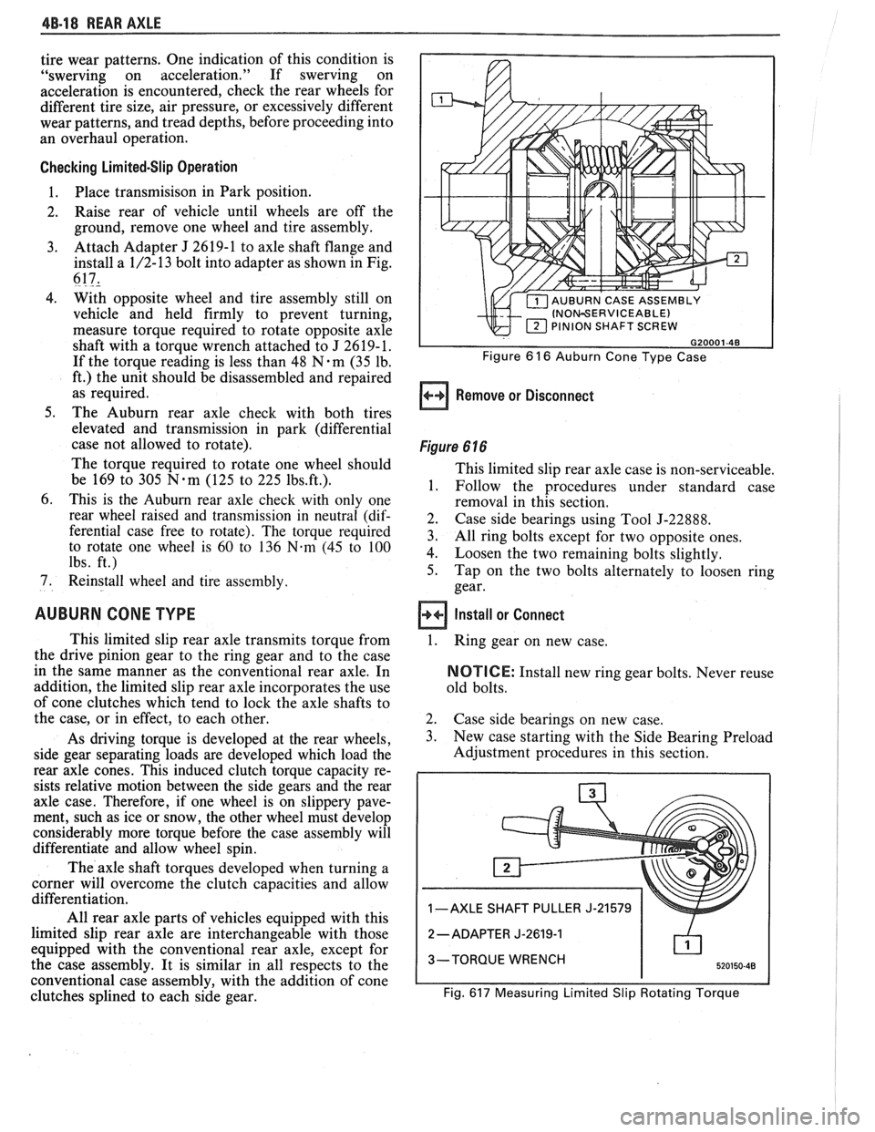
3. Attach Adapter J 2619-1 to axle shaft flange and
install a 1/2-13 bolt into adapter as shown in Fig.
617,
4. With opposite wheel and tire assembly still on
vehicle and held firmly to prevent turning,
measure torque required to rotate opposite axle
shaft with a torque wrench attached to J 2619-1.
If the torque reading is less than 48
N.m (35 lb.
ft.) the unit should be disassembled and repaired
as required.
5. The Auburn rear axle check with both tires
elevated and transmission in park (differential
case not allowed to rotate).
The torque required to rotate one wheel should
be 169 to 305
N-m (125 to 225 1bs.ft.).
6. This is the Auburn rear axle check with only one
rear wheel raised and transmission in neutral (dif-
ferential case free to rotate). The torque required
to rotate one wheel is
60 to 136 N-m (45 to 100
lbs. ft.)
7. Reinstall wheel and tire assembly.
AUBURN CONE TYPE
This limited slip rear axle transmits torque from
the drive pinion gear to the ring gear and to the case
in the same manner as the conventional rear axle. In
addition, the limited slip rear axle incorporates the use
of cone clutches which tend to lock the axle shafts to
the case, or in effect, to each other.
As driving torque is developed at the rear wheels,
side gear separating loads are developed which load the
rear axle cones. This induced clutch torque capacity re-
sists relative motion between the side gears and the rear
axle case. Therefore, if one wheel is on slippery pave-
ment, such as ice or snow, the other wheel must develop
considerably more torque before the case assembly will
differentiate and allow wheel spin.
The axle shaft torques developed when turning a
corner will overcome the clutch capacities and allow
differentiation.
All rear axle parts of vehicles equipped with this
limited slip rear axle are interchangeable with those
equipped with the conventional rear axle, except for
the case assembly. It is similar in all respects to the
conventional case assembly, with the addition of cone
clutches splined to each side gear.
INOWERVICEABLE) PINION SHAFT SCREW
Figure 6 16 Auburn Cone Type Case
Remove or Disconnect
Figure 6 16
This limited slip rear axle case is non-serviceable,
1. Follow the procedures under standard case
removal in this section.
2. Case side bearings using Tool J-22888.
3. All ring bolts except for two opposite ones.
4. Loosen the two remaining bolts slightly.
5. Tap on the two bolts alternately to loosen ring
gear.
Install or Connect
1.
Ring gear on new case.
NOTICE: Install new ring gear bolts. Never reuse
old bolts.
2. Case side bearings on new case.
3. New case starting with the Side Bearing Preload
Adjustment procedures in this section.
1 -AXLE SHAFT PULLER J-21579
2
-ADAPTER J-2619-1
3-TORQUE WRENCH
Fig.
617 Measuring Limited Slip Rotating Torque
Page 295 of 1825
5-2 BRAKES
GENERAL DESCRIPTION
COMPOSIE EASTER CYLINDER
This vehicle uses a composite master cylinder which has
an aluminum body and a clear nylon reservoir with fluid
level indicators. The master cylinder uses a "quick take-up" feature in the
rear chamber to reduce pedal travel which may result from
increased fluid displacement required to move the caliper
piston. The quick take-up master cylinder includes a spring
loaded ball check valve which holds pressure in the
large-
diameter rear chamber. When the brake is first applied, the
movement of the rear piston causes fluid to be displaced
forward, past the primary piston primary seal and into the
primary high pressure chamber, which feeds the front
brakes. At a predetermined pressure, 480-690
kPa (70-100
mi), the ball unseats and fluid from the largi! rear bore is
disblaced past the ball and into the reservoir. The primary
and secondary high pressure chambers supply pressure to
the front and rear brakes, respectively, in the usual way.
When the pedal is released, the large-bore chamber is filled
with fluid by drawing fluid from the reservoir around the
quick take-up lip seal, and also through a small orifice in the
ball seat.
BRAKE FLUID LEVEL INDICATOR
(Figure 1)
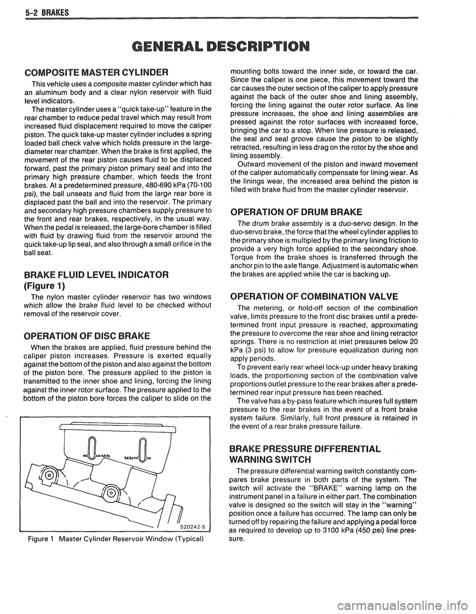
The nylon master cylinder reservoir has two windows
which allow the brake fluid level to be checked without
removal of the reservoir cover.
OPERATION OF DISC BRAKE
When the brakes are applied, fluid pressure behind the
caliper piston increases. Pressure is exerted equally
against the bottom of the piston and also against the bottom
of the piston bore. The pressure applied to the piston is
transmitted to the inner shoe and lining, forcing the lining
against the inner rotor surface. The pressure applied to the
bottom of the piston bore forces the caliper to slide on the
Figure
1 Master Cylinder Reservoir Window (Typical) mounting bolts toward the inner side,
or toward the car.
Since the caliper is one piece, this movement toward the
car causes the outer section of the caliper to apply pressure
against the back of the outer shoe and lining assembly,
forcing the lining against the outer rotor surface. As line
pressure increases, the shoe and lining assemblies are
pressed against the rotor surfaces with increased force,
bringing the car to a stop. When line pressure is released,
the seal and seal groove cause the piston to be slightly
retracted, resulting in less drag on the rotor by the shoe and
lining assembly.
Outward movement of the piston and inward movement
of the caliper automatically compensate for lining wear. As
the linings wear, the increased area behind the piston is
filled with brake fluid from the master cylinder reservoir.
OPERATION OF DRUM BRAKE
The drum brake assembly is a duo-servo design. In the
duo-servo brake, the force that the wheel cylinder applies to
the primary shoe is
multipled by the primary lining friction to
provide a very high force applied to the secondary shoe.
Torque from the brake shoes is transferred through the anchor pin to the axle flange. Adjustment is automatic when
the brakes are applied while the car is backing up.
OPERATION OF COMBINATION VALVE
The metering, or hold-off section of the combination
valve, limits pressure to the front disc brakes until a prede-
termined front input pressure is reached, approximating
the pressure to overcome the rear shoe and lining retractor
springs. There is no restriction at inlet pressures below 20
kPa (3 psi) to allow for pressure equalization during non
apply periods.
To prevent early rear wheel lock-up under heavy braking
loads, the proportioning section of the combination valve
proportions outlet pressure to the rear brakes after a prede-
termined rear input pressure has been reached.
The valve has a by-pass feature which insures full system
pressure to the rear brakes in the event of a front brake
system failure. Similarly, full front pressure is retained in
the event of a rear brake pressure failure.
BRAKE PRESSURE DIFFERENTIAL
WARNING
SWITCH
The pressure differential warning switch constantly com-
pares brake pressure in both parts of the system. The
switch will activate the "BRAKE" warning lamp on the
instrument panel in a failure in either part. The combination
valve is designed so the switch will stay in the "warning"
position once a failure has occurred. The lamp can only be
turned off by repairing the failure and applying a pedal force
as required to develop up to 3100
kPa (450 psi) line pres-
sure.
Page 345 of 1825
5F-2 SPECIFICATIONS AND SPECIAL TOOLS
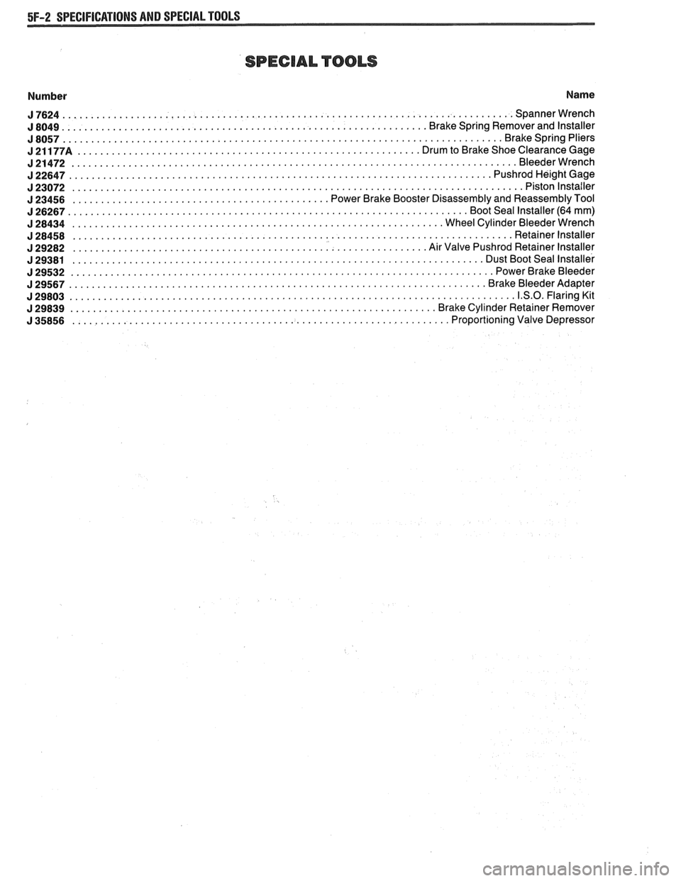
SPECIAL TOOLS
Number Name
J7624 ............................................................................... Spannerwrench
................................................................ J 8049 Brake Spring Remover and Installer
J8057 ............................................................................. Brakespringpliers
J21177A ............................................................ DrumtoBrakeShoeClearanceGage
J21472 .............................................................................. Bleederwrench
J22647 .......................................................................... PushrodHei ghtGage
J23072 ............................................................................... Pistonlnstailer
............................................. J 23456 Power Brake Booster Disassembly and Reassembly Tool
J26267 ...................................................................... BootSeallnstaller(64mm)
J28434 ................................................................. WheelCylinderBleederWrench
J28458 ............................................................................. Retainerlnstaller
.............................................................. J 29282 Air Valve Pushrod Retainer Installer
........................................................................ J 29381 Dust Boot Seal Installer
J29532 .......................................................................... PowerBrakeBleeder
J29567 ......................................................................... Br akeBleederAdapter
J29803 .............................................................................. 1.S.O.FlaringKit
................................................................ J 29839 Brake Cylinder Retainer Remover
.................................................................. J 35856 Proportioning Valve Depressor
Page 365 of 1825
BA2-14 2.8 LITER V-6
bores for oversize valves use tool 5-5330-1, 2 or 3,
respectively.
VALVE SEATS
Reconditioning the valve seats is very important,
because the seating of the valves must be perfect for the
engine to deliver the power and performance designed
into it.
Another important factor is the cooling of the
valve heads. Good contact between each valve and its
seat in the head is imperative to insure that the heat in
the valve head will be properly carried away.
Several different types of equipment are available
for reseating valve seats. The recommendations of the
manufacturer of the equipment being used should be
carefully followed to attain proper results.
VALVES
Valves that are pitted can be refaced, to the
proper angle, insuring correct relation between the
head and stem, on a valve
refacing machine. Valve
stems which show excessive wear, or valves that are
warped excessively should be replaced. When a valve
head which is warped excessively is
refaced, a knife
edge will be ground on part or all of the valve head due
to the amount of metal that must be removed to
completely
reface the valve. Knife edges lead to
breakage, burning or preignition due to heat localizing
on this knife edge. If the edge of the valve head is less
than
.8mm thick after grinding, replace the valve.
Several different types of equipment are available
for
refacing valves. The recommendations of the
manufacturer of the equipment being used should be
carefully followed to attain the proper results.
Assembly
Insert a valve in the proper port.
Install a valve stem seal over the valve stem and
valve guide base inlet only.
Drop an oil shedder and valve rotator over the
exhaust and a valve spring cap over the valve
spring.
Using tool
5-8062 compress the valve spring.
Install the square cut
"0" ring around the valve
stem in the lower groove, making sure it is not
twisted.
Insert valve, stem key locks and release tool.
Install the valve locks and release the compressor
tool making sure that the locks seat properly in
the upper groove of the valve stem. Grease may
be used to hold the locks in place while releasing
the compressor tool.
Install the remaining valves.
Check each valve stem oil seal by placing valve
stem leak detector, tool J-23994, over the end of
the valve stem and against the cap. Operate the
vacuum pump and make sure no air leaks pass the
seal.
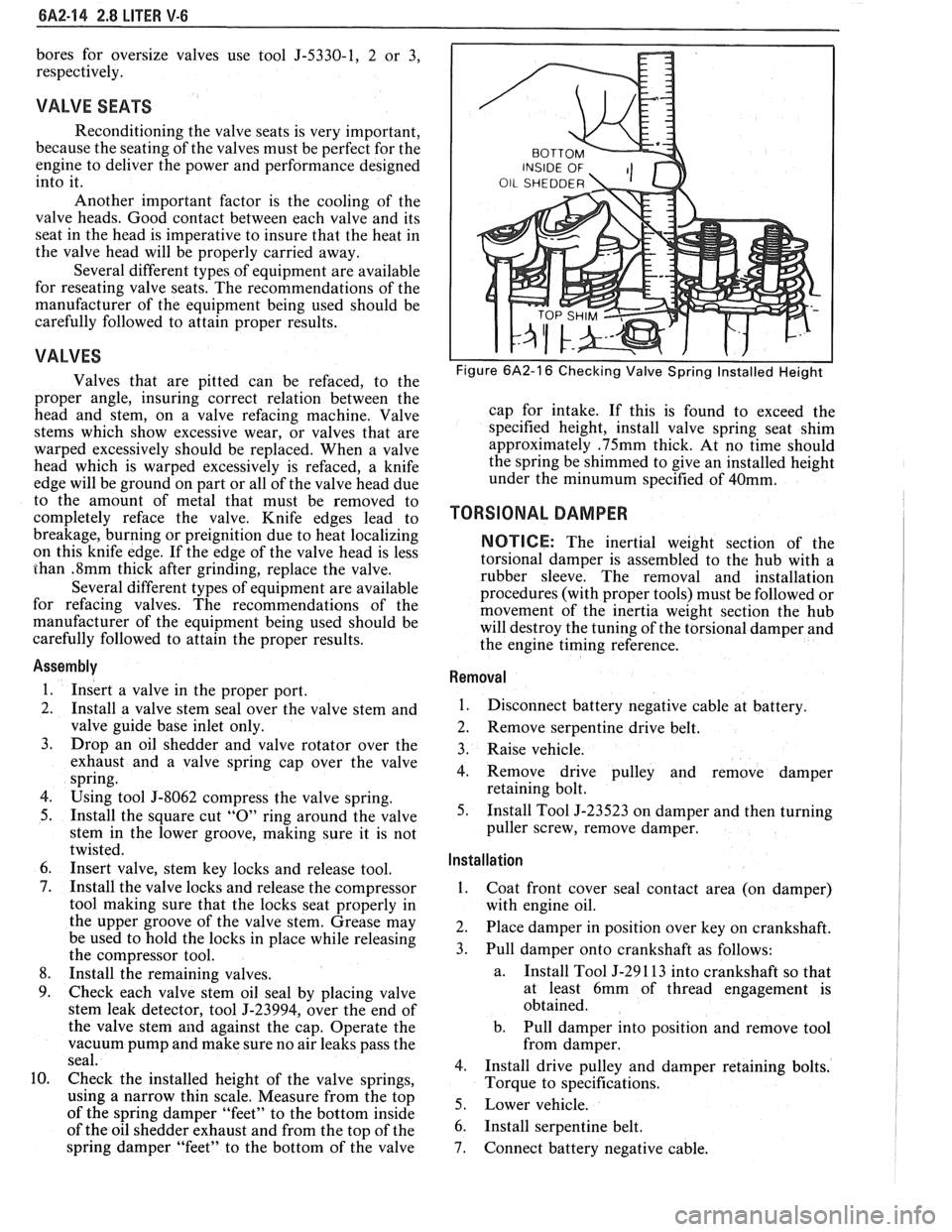
Check the installed height of the valve springs,
using
a narrow thin scale. Measure from the top
of the spring damper "feet" to the bottom inside
of the oil shedder exhaust and from the top of the
spring damper "feet" to the bottom of the valve
Figure 6A2-16 Checking Valve Spring Installed Height
cap for intake. If this is found to exceed the
specified height, install valve spring seat shim
approximately
.75mm thick. At no time should
the spring be shimmed to give an installed height
under the
minumum specified of 40mm.
TORSIONAL DAMPER
NOTICE: The inertial weight section of the
torsional damper is assembled to the hub with a
rubber sleeve. The removal and installation
procedures (with proper tools) must be followed or
movement of the inertia weight section the hub
will destroy the tuning of the torsional damper and
the engine timing reference.
Removal
1.
Disconnect battery negative cable at battery.
2. Remove serpentine drive belt.
3. Raise vehicle.
4. Remove drive pulley and remove damper
retaining bolt.
5. Install Tool J-23523 on damper and then turning
puller screw, remove damper.
Installation ,
1.
Coat front cover seal contact area (on damper)
with engine oil.
2. Place damper in position over key on crankshaft.
3. Pull damper onto crankshaft as follows:
a. Install
Tool J-29 1 13 into crankshaft so that
at least 6mm of thread engagement is
obtained.
b. Pull damper into position and remove tool
from damper.
4. Install drive pulley and damper retaining bolts.
Torque to specifications.
5. Lower vehicle.
6. Install serpentine belt.
7. Connect battery negative cable.
Page 373 of 1825
rebore the cylinder to fit an oversize piston in
order to insure satisfactory results.
3. If cylinder bore is tapered 0. lmm or more or is
out-of-round
O.lmm or more, it is advisable to
rebore for the smallest possible oversize piston
and rings. Below these limits, the cylinder bore
can be trued up with honing.
4. Clean carbon from piston surfaces and under side
of piston heads. Clean carbon from ring grooves
with suitable tool and remove any gum or varnish
from piston skirts with suitable solvent.
5. Carefully examine pistons for
rough or scored
surfaces; cracks in skirt or head; cracked or
broken ring lands; chipped or uneven wearing
pistons would cause rings to seat improperly or
have excessive clearance in ring grooves.
Damaged or faulty pistons should be replaced.
The pistons are cam ground, which means that
the diameter at a right angle to the wrist pin is
greater than the diameter parallel to the wrist pin.
When a piston is checked for size, it must be done
at points 90" to the piston pin. The piston should
be checked (for fitting purposes) in a plane
through the piston pin centerline.
6. Inspect surfaces of wrist pins and check for wear
by measuring worn or unworn surfaces with
micrometers. Occasionally pins will be found
tight due to gum or varnish deposits. This may be
corrected by removing the deposit with a suitable
solvent. If piston bosses are worn out-of-round or
oversize, the piston and pin assembly must be
replaced. Oversize pins are not practical due to
the pin being a press fit in the connecting rod.
Piston pins must fit the piston with an easy finger
push at 70°F (21°C)
(.0065 to .0091mm
clearance).
7. Examine all piston rings for scores, chips or
cracks. Check compression rings for tension by
comparing with new rings. Check gap of
compression rings by placing rings in bore at
bottom of ring travel. Measure gap with feeler
gage. Gap should be between
0.25mm and 0.
50mm. If gaps are excessive (over 0.50mm) it
indicates the rings have worn considerably and
should be replaced. Bore wear should be checked
before rings are replaced,
. l25mm bore wear will
result in
.39mm increase in ring gap.
Assembly
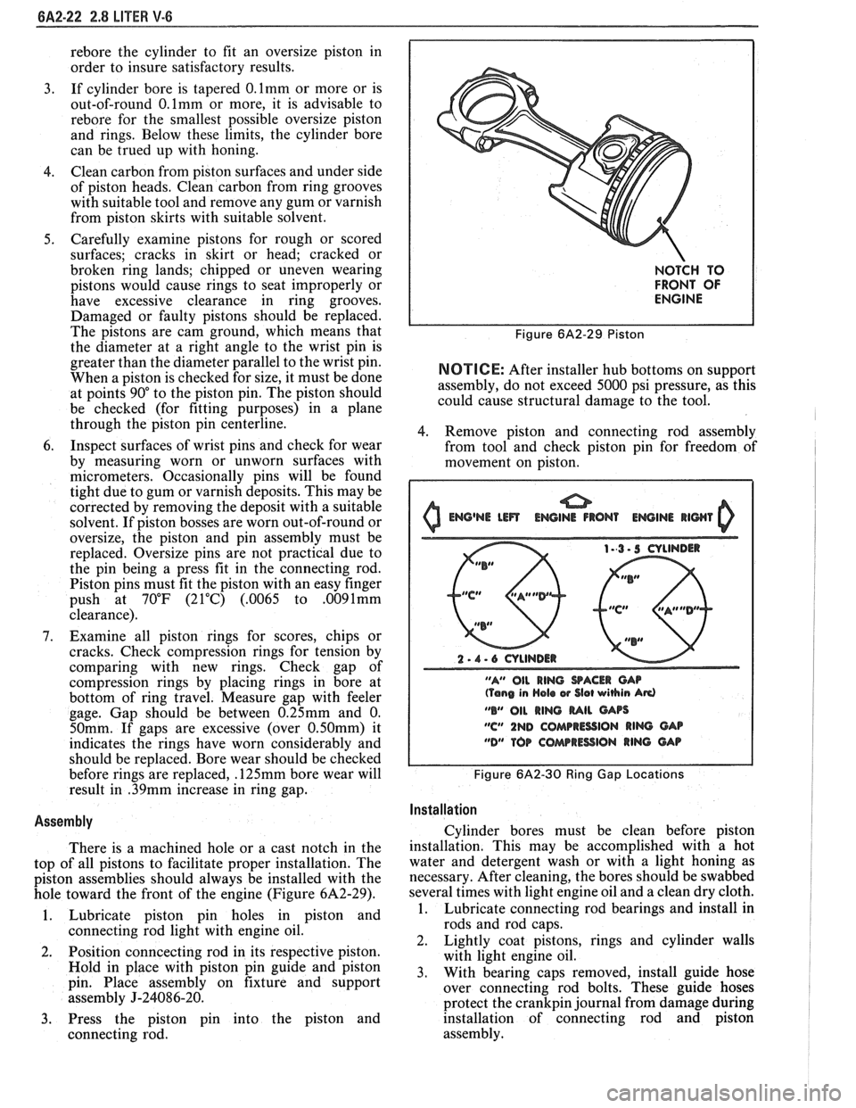
There is a machined hole or a cast notch in the
top of all pistons to facilitate proper installation. The
piston assemblies should always be installed with the
hole toward the front of the engine (Figure
6A2-29).
1. Lubricate piston pin holes in piston and
connecting rod light with engine oil.
2. Position
conncecting rod in its respective piston.
Hold in place with piston pin guide and piston
pin. Place assembly on fixture and support
assembly
J-24086-20.
3. Press the piston pin into the piston and
connecting rod.
NOTCH TO
FRONT OF
ENGINE
Figure 6A2-29 Piston
NOTICE: After installer hub bottoms on support
assembly, do not exceed 5000 psi pressure, as this
could cause structural damage to the tool.
4. Remove piston and connecting rod assembly
from tool and check piston pin for freedom of
movement on piston.
0 Emj@NE Lm ENGINE IRON1 EWINI llWl 0
2 - 1 - 6 CYLINDER
"A" OIL
RING SACER CAP (Tang in Hola w Slot wihin Ad
"B" 011 RING MIL GArs
"C" 1ND COMPRESSION RIM GAB
"DM TOP COAarRESSlON RING GAP
Figure 6A2-30 Ring Gap Locations I
I
Installation I
Cylinder bores must be clean before piston
installation. This may be accomplished with a hot
water and detergent wash or with a light honing as
necessary. After cleaning, the bores should be swabbed
several times with light engine oil and a clean dry cloth.
1. Lubricate connecting rod bearings and install in
rods and rod caps.
2. Lightly coat pistons, rings and cylinder walls
with light engine oil.
3. With bearing caps removed, install guide hose
over connecting rod bolts. These guide hoses
protect the
crankpin journal from damage during
installation of connecting rod and piston
assembly.
Page 374 of 1825
2.8 LITER V-6 8A2-23
4. Make sure the gap in the oil ring rails are in "up"
position toward center of engine and the gaps of
the compression rings are positioned as shown in
Figure
6A2-30.
5. Install each connecting rod and piston assembly
in its respective bore. Install with connecting rod
bearing tang slots on side opposite camshaft. Use
Tool J-8037 or J-8910 to compress the rings.
Guide the connecting rod into place on the
crankshaft journal.
Use a hammer handle and light blows to install
the piston into the bore. Hold the ring
compressor firmly against the cylinder block
until all piston rings have entered the cylinder
bore.
6. Install the bearing caps and torque nuts to
specifications. If bearing replacement is required
refer to "Connecting Rod Bearings".
Be sure to install new pistons in the same
cylinders for which they were fitted, and used
pistons in the same cylinder from which they
were removed. Each connecting rod and bearing
cap should be marked, beginning at the front of
the engine.
On V-6 engines, 1,3 and 5 are in the right bank
and 2,
4 and 6 are in the left bank. The numbers
on the connecting rod and bearing cap must be on
the same side when installed in the cylinder bore.
If a connecting rod is ever transposed from one
block or cylinder to another, new bearings should
be fitted and the connecting rod should be
numbered to correspond with the new cylinder
number.
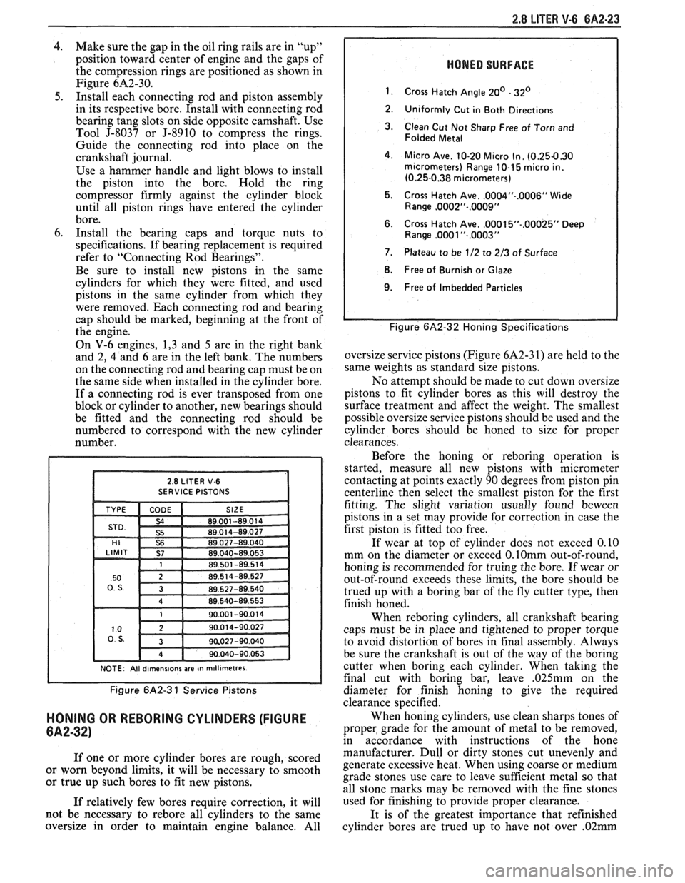
NOTE. All dlrnenslons are In rn~ll~rnetres.
Figure 6A2-3 1 Service Pistons
HONING OR REBORING CYLINDERS (FIGURE
6A2-32)
If one or more cylinder bores are rough, scored
or worn beyond limits, it will be necessary to smooth
or true up such bores to fit new pistons.
If relatively few bores require correction, it will
not be necessary to
rebore all cylinders to the same
oversize in order to maintain engine balance. All
HONED SURFACE
1.
Cross Hatch Angle 20' - 32'
2.
Uniformly Cut in Both Directions
3. Clean Cut Not Sharp Free of Torn and
Folded Metal
4. Micro Ave. 10-20 Micro In. (0.254.30 micrometers) Range 10-1 5 micro in.
(0.25-0.38 micrometers)
5. Cross Hatch Ave.
.0004"-.0006" Wide
Range ,0002"-.0009"
6. Cross Hatch Ave. ,0001 5"-.00025" Deep Ranw ,0081 "-.0003"
7. Plateau to be 1/2 to 2/3 of Surface
8. Free of Burnish or Glaze
I 9. Free of Imbedded Particles I
I I Figure 6A2-32 Honing Specifications
oversize service pistons (Figure 6A2-3 1) are held to the
same weights as standard size pistons.
No attempt should be made to cut down oversize
pistons to fit cylinder bores as this will destroy the
surface treatment and affect the weight. The smallest
possible oversize service pistons should be used and the
cylinder bores should be honed to size for proper
clearances.
Before the honing or
reboring operation is
started, measure all new pistons with micrometer
contacting at points exactly 90 degrees from piston pin
centerline then select the smallest piston for the first
fitting. The slight variation usually found
beween
pistons in a set may provide for correction in case the
first piston is fitted too free.
If wear at top of cylinder does not exceed 0.10
mm on the diameter or exceed
0.lOmm out-of-round,
honing is recommended for truing the bore. If wear or
out-of-round exceeds these limits, the bore should be
trued up with a boring bar of the fly cutter type, then
finish honed.
When
reboring cylinders, all crankshaft bearing
caps must be in place and tightened to proper torque
to avoid distortion of bores in final assembly. Always
be sure the crankshaft is out of the way of the boring
cutter when boring each cylinder. When taking the
final cut with boring bar, leave
,025mm on the
diameter for finish honing to give the required
clearance specified.
When honing cylinders, use clean sharps tones of
proper grade for the amount of metal to be removed,
in accordance with instructions of the hone
manufacturer. Dull or dirty stones cut unevenly and
generate excessive heat. When using coarse or medium
grade stones use care to leave sufficient metal so that
all stone marks may be removed with the fine stones
used for finishing to provide proper clearance.
It is of the greatest importance that refinished
cylinder bores are trued up to have not over
.02mm