1988 PONTIAC FIERO ESP
[x] Cancel search: ESPPage 375 of 1825
6A2-24 2.8 LITER V-6
out-of-round or taper. Each bore must be final honed
to remove all stone or cutter marks and provide a
smooth surface. During final honing, each piston must
be fitted individually to the bore in which it will be
installed and should be marked to insure correct
installation.
After final honing and before the piston is
checked for fit, each cylinder bore must be thoroughly
washed to remove all traces of abrasives and then dried
thoroughly. The dry bore should then be brushed clean
with a power-driven fibre brush. If all traces of the
abrasives are not removed, rapid wear of new pistons
and rings will result.
FITTING PISTONS
1. Remove all rings
from pistons which will be
fitted. It is not necessary to separate rods from
pistons. If an excess amount of varnish or carbon
appears as a ridge at the top of the cylinder,
remove by scraping or sanding.
2. Wipe bores
and pistons clean, removing oil or
other foreign material. Select a piston-rod
assembly for the bore to be fitted (or piston and
pin if a new piston is being fitted) and position
down into the bore with the top of piston down.
The piston should fall free by its own weight
through the bore when when the bottom of the
piston skirt is 12 to 25mm from top of block.
Caution must be used to insure piston is not
damaged when it "falls" through the cylinder. If
it does not, the piston fit is too tight and another
piston should be selected until the piston will slide
freely through the bore without any force being
applied. Mark piston and bore for proper
assembly.
3. After a piston has been slected, which will slide
freely through a bore, it must be determined if
piston fit will be too loose. This is done by placing
a ,060 mm feeler gage for used pistons and a
.050
mm feeler gage for new pistons at least 150mm
long and not over 12mm wide, down into the
same bore with selected piston while holding
feeler to top of the bore.
Position selected piston and feeler down into the
bore until the bottom of the skirt is again 12 to
25 mm from top of block, being sure that the
feeler gage is
90" from the pin. If the piston hangs
on the feeler gage and does not fall free, it
indicates that the piston is correctly fitted to that
respective bore. Mark both piston and bore before
going to the next bore. If the piston fell free
during this check with the
.060mm feeler gage (.
050mm feeler gage for new pistons) then that
particular piston is too small for the bore and a
larger diameter piston will be required.
When checking more than one bore, it is very
possible that what may be a piston too small for one
bore will be a correct fit in another.
PISTON RINGS
When new piston rings are installed without
reboring cylinders, the glazed cylinder walls should be
slightly dulled, but without increasing the bore
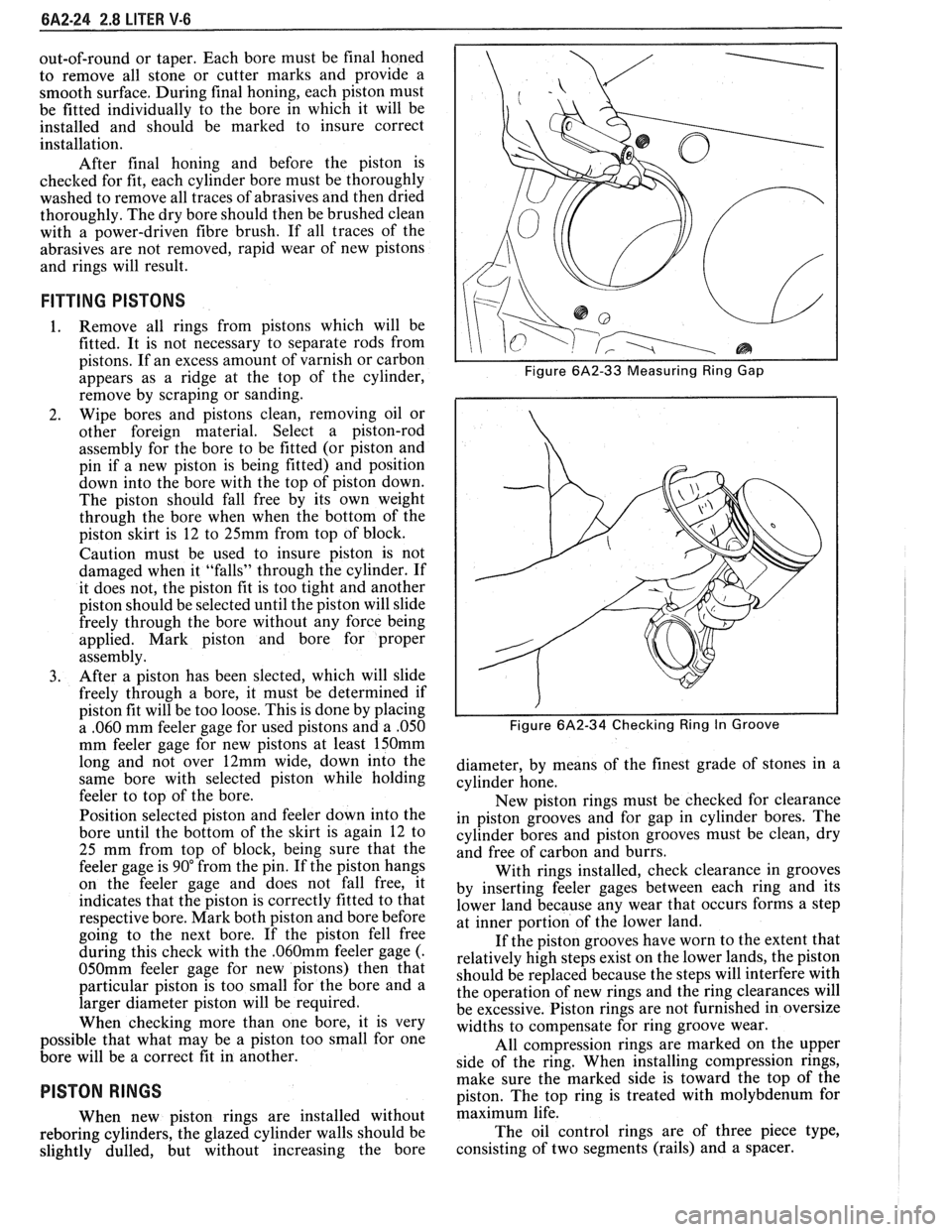
I I Figure 6A2-33 Measuring Ring Gap
i I
I I Figure 6A2-34 Checking Ring In Groove
diameter, by means of the finest grade of stones in a
cylinder hone.
New piston rings must be checked for clearance
in piston grooves and for gap in cylinder bores. The
cylinder bores and piston grooves must be clean, dry
and free of carbon and burrs.
With rings installed, check clearance in grooves
by inserting feeler gages between each ring and its
lower land because any wear that occurs forms a step
at inner portion of the lower land.
If the piston grooves have worn to the extent that
relatively high steps exist on the lower lands, the piston
should be replaced because the steps will interfere with
the operation of new rings and the ring clearances will
be excessive. Piston rings are not furnished in oversize
widths to compensate for ring groove wear.
All compression rings are marked on the upper
side of the ring. When installing compression rings,
make sure the marked side is toward the top of the
piston. The top ring is treated with molybdenum for
maximum life.
The oil control rings are of three piece type,
consisting of two segments (rails) and a spacer.
Page 376 of 1825
2.8 LITER V-6 6A2-25
Fitting
1. Select rings comparable in size to the piston being
used.
2. Slip
the compression ring in the cylinder bore;
then press the ring down into the cylinder bore
about 6mm above ring travel. Be sure ring is
square with cylinder wall.
3. Measure the space or gap between the ends of the
ring with a feeler gage (Figure
6A2-33).
4. If
the gap between the ends of the ring is below
specifications, remove the ring and try another
for fit.
5. Fit each compression ring to the cylinder in
which it is going to be used.
6. If the pistons have not been cleaned and inspected
as previously outlined, do so.
7. Slip the outer surface of the top and second
compression ring into the respective piston ring
groove and roll the ring entirely around the
groove (Figure
6A2-34). If binding occurs at any
point, the cause should be determined. If there is
a ring groove, remove by dressing with a fine cut
file. If the binding is caused by a distorted ring,
check a new ring.
Installation
1. Install oil ring spacer in groove being sure ends
are butted and not overlapped.
2. Hold
spacer ends butted and install lower steel oil
ring rail.
3. Install upper
steel oil ring rail with gap staggered.
4. Flex
the oil ring assembly to make sure ring is
free. If binding occurs, the cause should be
detemined. If caused by ring groove, remove by
dressing groove with a fine cut file. If binding is
caused by a distorted ring, check a new ring.
5. Install second compression ring. Stagger gap
from other rings.
6. Install top compression ring with gap properly
located.
ENGINE ASSEMBLY
Removal
Disconnect battery.
Remove air cleaner.
Remove hood. Drain radiator.
Remove lower radiator hose.
Remove upper fan shroud.
Remove upper radiator hose and coolant
recovery hose.
Remove transmission cooler lines. Remove radiator.
Remove fan assembly.
Remove heater hoses.
Disconnect carburetor linkage, includes cruise
control detent cable.
Remove vacuum brake booster line.
Remove distributor cap and lay wiring aside.
Disconnect necessary wires and hoses.
Remove power steering pump and lay aside. Raise
vehicle.
Remove exhaust pipes at exhaust manifold.
Remove dust cover.
Remove converter bolts.
Disconnect starter wires.
Remove bell housing bolts.
Remove motor mount through bolts.
Disconnect fuel lines at fuel pump.
Lower vehicle. Support transmission.
Remove
A.I.R./Converter pipes bracket.
Remove engine, include removing wire from
bracket at rear left of engine.
Installation
Position engine assembly in vehicle.
Attach motor mount to engine brackets and
lower engine in place.
Remove engine lifting device.
Remove transmission floor jack.
Raise vehicle on hoist.
Install mount "through" bolts. Torque to
specifications.
Install bell housing bolts. Torque to
specifications.
On vehicles with automatic transmission, install
converter to flywheel attaching bolts. Torque to
specifications.
Install flywheel splash shield of conveter housing
cover as applicable. Torque attaching bolts to
specifications.
Install starter wires.
Connect fuel lines.
Connect exhaust pipe at manifold.
Lower vehicle on hoist.
Reinstall power steering pump, if so equipped.
Connect necessary wires and hoses.
Install radiator and fan shroud and reconnect
radiator and heater hoses.
Fill cooling system.
Fill crankcase with oil. See owner's manual for
specifications.
Install air cleaner.
Install hood.
Connect battery cables.
NOTICE: To avoid possible arcing of battery,
connect positive battery cable first.
22. Start engine, check for leaks and check timing.
CRANKSHAFT
The crankshaft can be removed while the engine
is dissasembled for overhaul, as previously outlined or
without complete disassembly.
Removal
1. With the engine removed from the vehicle,
remove the clutch assembly (if equipped) and
flywheel. Mount engine in stand and clamp
securely.
Page 377 of 1825
6A2-26 2.8 LITER V-6
2. Remove the spark plugs. Installation
3. Remove
crankshaft pulley and torsional damper. 1. Install rear main bearing oil seal in cylinder block
4. Remove oil pan and oil pump. and
rear bearing cap grooves.
5. Remove water pump, crankcase front cover, 2. Lubricate seal with engine oil. Keep oil off
camshaft sprocket and timing chain. parting
line surface.
3. Install main bearings in cylinder block and main
6. Check the connecting rod caps for cylinder
bearing caps then lubricate bearing surface with
number identification. If necessary mark them.
engine oil.
7. Remove the connecting rod caps and
push the
4. 1n;tall crankshaft, being careful not to damage
pistons to top of bores.
bearing surfaces.
8. Remove main bearing caps and lift crankshaft out 5. Recheck bearing clearances using plastigage.
of cylinder block. 6.
Apply a thin coat of anaerobic sealant
# 1052357
9. Remove rear
main bearing oil seal and main or
equivalent to rear of the block mating surface
bearings from cylinder block and main bearing or corresponding
surface or rear main cap only.
caps. Do
not allow sealer on crankshaft or seal.
7. Install main bearing caps with arrow pointing
Cleaning and Inspection toward front of engine.
8. Torque all except
#3 main bearing cap bolts to
1. Wash crankshaft in solvent and dry with
specifications. Torque
#3 main bearing cap bolts
compressed air. to 14-16
N-m (10-12 lbs. ft.) then tap end of
2. Measure
dimensions of main bearing journals and crankshaft, first rearward then forward with a
crankpins with a micrometer for out-of-round, lead
hammer. This will line up rear main bearing
taper or undersize (See Specifications). and crankshaft
thrust surfaces.
Retorque all main
3. Check
crankshaft for run-out by supporting at bearing
cap bolts to specifications.
the front and rear main bearings journals in "V" 9. Measure crankshaft
end play with a feeler gage.
blocks and check at the front and rear Force crankshaft forward and measure clearance
intermediate journals with a dial indicator (See between the front of the
#3 main bearing and
Specifications). crankshaft thrust surface.
4. Replace or recondition the crankshaft if out of 10.
Install flywheel and torque to specifications.
specifications.
SPROCKET OR GEAR REPLACEMENT
Remove crankshaft sprocket using Tool J-5825,
install using Tool J-5590.
GENERAL DATA
TYPE .................................................................................................................................... 60" V-6
DISPLACEMENT
............................................................................................................. 2.8 Liter
RPO
........................................................................................................................................... LB8
BORE ......................................................................................................................................... 89
STROKE
................................... .... ............................................................................................... 76
COMPRESSION RATIO
....................................................................................................... 8.9: 1
FIRING ORDER
.......................................................................................................... 1-2-3-4-5-6
Cylinder Bore
DIAMETER .............................................................................................................. 88.992-88.070
OUT OF ROUND
............................................................................................................. .02 Max.
TAPER-THRUST SIDE
................................................................................................. .02 Max.
Piston
CLEARANCE .................................................................................................................. .O 17-,043
Piston Ring
Page 395 of 1825
6A3-16 V-8 ENGINE
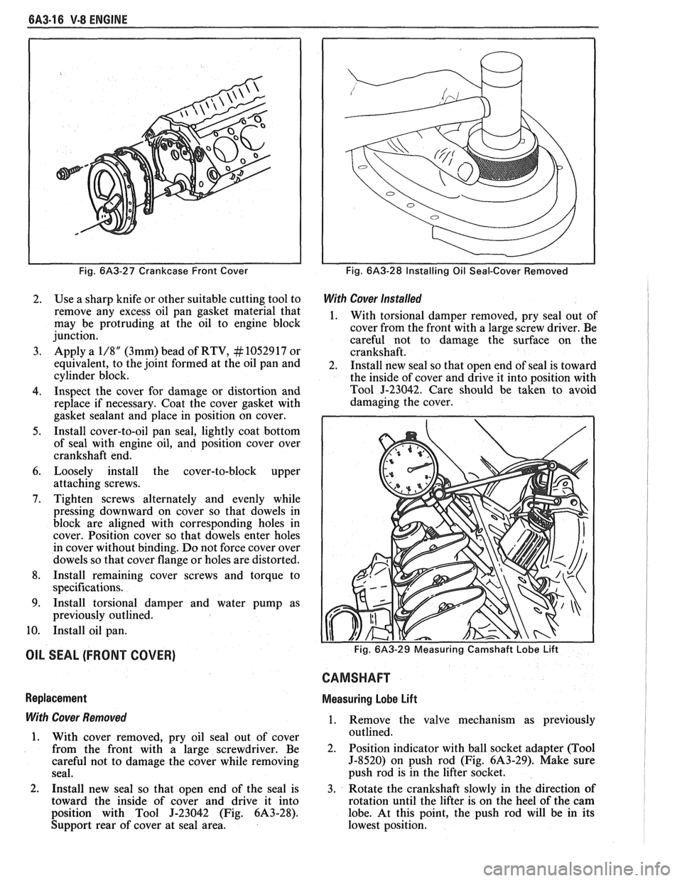
Fig. 6A3-27 Crankcase Front Cover
2. Use a sharp knife or other suitable cutting tool to
remove any excess oil pan gasket material that
may be protruding at the oil to engine block
junction.
3. Apply a 1/8" (3mm) bead of RTV, # 10529 17 or
equivalent, to the joint formed at the oil pan and
cylinder block.
4. Inspect the cover for damage or distortion and
replace if necessary. Coat the cover gasket with
gasket sealant and place in position on cover.
5. Install cover-to-oil pan seal, lightly coat bottom
of seal with engine oil, and position cover over
crankshaft end.
6. Loosely install the cover-to-block upper
attaching screws.
7. Tighten screws alternately and evenly while
pressing downward on cover so that dowels in
block are aligned with corresponding holes in
cover. Position cover so that dowels enter holes
in cover without binding.
Do not force cover over
dowels so that cover flange or holes are distorted.
8. Install remaining cover screws and torque to
specifications.
9. Install torsional damper and water pump as
previously outlined.
10. Install oil pan.
OIL SEAL (FRONT COVER)
Replacement
With Cover Removed
1. With cover removed, pry oil seal out of cover
from the front with a large screwdriver. Be
careful not to damage the cover while removing
seal.
2. Install new seal so that open end of the seal is
toward the inside of cover and drive it into
position with Tool
J-23042 (Fig. 6A3-28).
Support rear of cover at seal area.
Fig. 6A3-28 Installing Oil Seal-Cover Removed
With Cover Installed
1. With torsional damper removed, pry seal out of
cover from the front with a large screw driver. Be
careful not to damage the surface on the
crankshaft.
2. Install new seal so that open end of seal is toward
the inside of cover and drive it into position with
Tool
J-23042. Care should be taken to avoid
damaging the cover.
CAMSHAFT
Measuring Lobe Lift
1. Remove the valve mechanism as previously
outlined.
2. Position indicator with ball socket adapter (Tool
5-8520) on push rod (Fig. 6A3-29). Make sure
push rod is in the lifter socket.
3. Rotate the crankshaft slowly in the direction of
rotation until the lifter is on the heel of the cam
lobe. At this point, the push rod will be in its
lowest position.
Page 404 of 1825
V-8 ENGINE 6A3-25
Assembly
1. Lubricate piston pin holes in piston and
connecting rod to facilitate installation of pin.
2. Place connecting rod in piston and hold in place
with piston pin guide and piston pin. Place
assembly on fixture and support assembly.
3. Using piston pin installer, 5-24086-9, press the
piston pin into the piston and connecting rod (Fig.
6A3-46).
NOTICE: After installer hub bottoms on support
assembly, do not exceed
5000 psi pressure, as this
could cause structural damage to the tool.
4. Remove piston
and connecting rod assembly
from tool and check piston for freedom of
movement on piston pin.
Piston Rings
All compression rings are marked on the upper
side of the ring. When installing compression rings,
make sure the MARKED SIDE IS TOWARD THE
TOP
OF THE PISTON. The top ring is chrome faced,
or treated with molybdenum for maximum life. The
second compression ring is a tapered face acting as
both a compression and oil control ring.
The oil control rings are of three piece type,
consisting of two segments (rails) and a spacer.
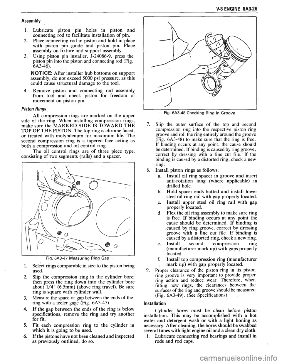
Fig. 6A3-47 Measuring Ring Gap
1. Select rings comparable in size to the piston being
used.
2. Slip the compression ring in the cylinder bore;
then press the ring down into the cylinder bore
about
1/4" (6.5mm) (above ring travel). Be sure
ring is square with cylinder wall.
3. Measure the space or gap between the ends of the
ring with a feeler gage (Fig.
6A3-47).
4. If the gap between the ends of the ring is below
specifications, remove the ring and try another
for fit.
5. Fit each compression ring to the cylinder in
which it is going to be used.
6. If the pistons have not been cleaned and inspected
as previously outlined, do so.
Fig. 6A3-48 Checking Ring in Groove
7. Slip the outer surface of the top and second
compression ring into the respective piston ring
groove and roll the ring entirely around the groove
(Fig.
6A3-48) to make sure that the ring is free.
If binding occurs at any point, the cause should
be determined. If binding is caused by ring groove,
correct by dressing with a fine cut file. If
the
binding is caused by a distorted ring, check a new
ring.
8. Install piston rings as follows:
a. Install oil ring spacer in groove and insert
anti-rotation tang (where applicable) in
drilled hole.
b. Hold spacer ends butted and install lower
steel oil ring rail with gap properly located.
c. Install
upper steel oil ring rail with gap
properly located.
d. Flex the oil ring assembly to make sure ring
is free. If binding occurs at any point the
cause should be determined. If binding is
caused by ring groove, correct by dressing
groove with a fine cut file. If binding is
caused by a distorted ring, check a new ring.
e. Install second compression ring
(manufacturer mark up) with gaps properly
located.
f. Install top compression ring (manufacturer
mark up) with gap properly located.
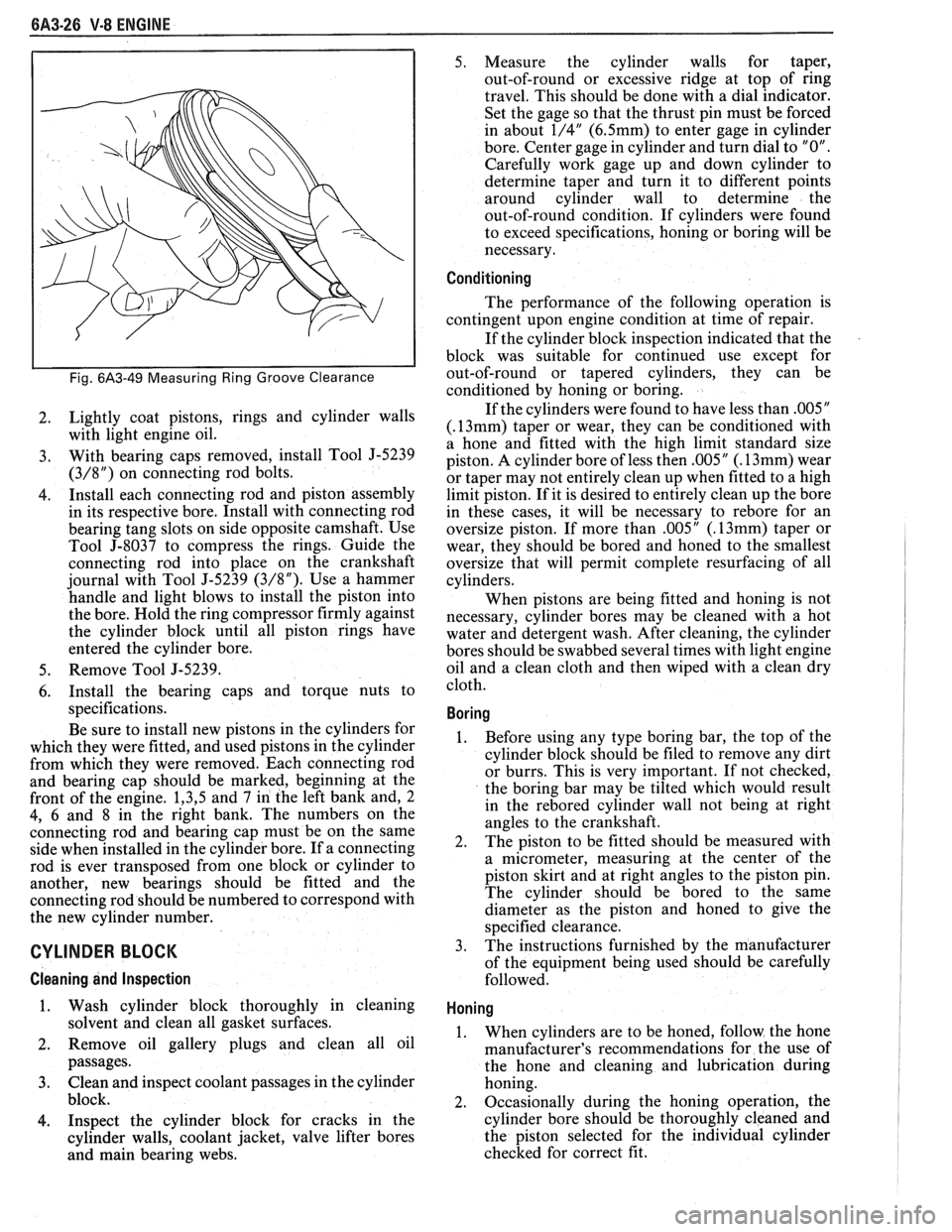
9. Proper clearance of the piston ring in its piston
ring groove is very important to provide proper
ring action and reduce wear. Therefore, when
fitting new rings, the clearances between the
surfaces of the ring and groove should be measured
(Fig.
6A3-49). (See Specifications).
Installation
Cylinder bores must be clean before piston
installation. This may be accomplished with a hot
water and detergent wash or with a light honing as
necessary. After cleaning, the bores should be swabbed
several times with light engine oil and a clean dry cloth.
1. Lubricate connecting rod bearings and install in
rods and rod caps.
Page 405 of 1825
6A3-26 V-8 ENGINE
Fig. 6A3-49 Measuring Ring Groove Clearance
2. Lightly coat pistons, rings
and cylinder walls
with light engine oil.
3. With bearing caps removed, install Tool J-5239
(3/8") on connecting rod bolts.
4. Install
each connecting rod and piston assembly
in its respective bore. Install with connecting rod
bearing tang slots on side opposite camshaft. Use
Tool
5-8037 to compress the rings. Guide the
connecting rod into place on the crankshaft
journal with Tool
5-5239 (3/8"). Use a hammer
handle and light blows to install the piston into
the bore. Hold the ring compressor firmly against
the cylinder block until all piston rings have
entered the cylinder bore.
5. Remove Tool J-5239.
6. Install the bearing caps and torque nuts to
specifications.
Be sure to install new pistons in the cylinders for
which they were fitted, and used pistons in the cylinder
from which they were removed. Each connecting rod
and bearing cap should be marked, beginning at the
front of the engine.
1,3,5 and 7 in the left bank and, 2
4, 6 and 8 in the right bank. The numbers on the
connecting rod and bearing cap must be on the same
side when installed in the cylinder bore. If a connecting
rod is ever transposed from one block or cylinder to
another, new bearings should be fitted and the
connecting rod should be numbered to correspond with
the new cylinder number.
CYLINDER BLOCK
Cleaning and Inspection
1. Wash cylinder block thoroughly in cleaning
solvent and clean all gasket surfaces.
2. Remove oil gallery plugs and clean all oil
passages.
3. Clean and inspect coolant passages in the cylinder
block.
4. Inspect the cylinder block for cracks in the
cylinder walls, coolant jacket, valve lifter bores
and main bearing webs. 5.
Measure the cylinder walls for taper,
out-of-round or excessive ridge at top of ring
travel. This should be done with a dial indicator.
Set the gage so that the thrust pin must be forced
in about
1/4" (6.5mm) to enter gage in cylinder
bore. Center gage in cylinder and turn dial to
"0".
Carefully work gage up and down cylinder to
determine taper and turn it to different points
around cylinder wall to determine the
out-of-round condition. If cylinders were found
to exceed specifications, honing or boring will be
necessary.
Conditioning
The performance of the following operation is
contingent upon engine condition at time of repair.
If the cylinder block inspection indicated that the
block was suitable for continued use except for
out-of-round or tapered cylinders, they can be
conditioned by honing or boring.
If the cylinders were found to have less than
.005"
(.13mm) taper or wear, they can be conditioned with
a hone and fitted with the high limit standard size
piston. A cylinder bore of less then
.005" (. 13mm) wear
or taper may not entirely clean up when fitted to a high
limit piston. If it is desired to entirely clean up the bore
in these cases, it will be necessary to
rebore for an
oversize piston. If more than
.005" (. 13mm) taper or
wear, they should be bored and honed to the smallest
oversize that will permit complete resurfacing of all
cylinders.
When pistons are being fitted and honing is not
necessary, cylinder bores may be cleaned with a hot
water and detergent wash. After cleaning, the cylinder
bores should be swabbed several times with light engine
oil and a clean cloth and then wiped with a clean dry
cloth.
Boring
1. Before using any type boring bar, the top of the
cylinder block should be filed to remove any dirt
or burrs. This is very important. If not checked,
the boring bar may be tilted which would result
in the
rebored cylinder wall not being at right
angles to the crankshaft.
2. The
piston to be fitted should be measured with
a micrometer, measuring at the center of the
piston skirt and at right angles to the piston pin.
The cylinder should be bored to the same
diameter as the piston and honed to give the
specified clearance.
3.
The instructions furnished by the manufacturer
of the equipment being used should be carefully
followed.
Honing
1. When cylinders are to be honed, follow the hone
manufacturer's recommendations for the use of
the hone and cleaning and lubrication during
honing.
2. Occasionally during the honing operation, the
cylinder bore should be thoroughly cleaned and
the piston selected for the individual cylinder
checked for correct fit.
Page 407 of 1825
6A3-28 V-8 ENGINE
16. Install
radiator and fan shroud and reconnect
radiator and heater hoses.
17. Fill cooling system.
18. Fill
crankcase with oil. See owner's manual for
specifications.
19. Install air cleaner.
20. Install hood.
21. Connect battery cables.
NOTICE: To avoid possible arcing of battery,
connect positive battery cable first.
22. Start engine, check for leaks and check timing.
CRANKSHAFT
The crankshaft can be removed while the engine
is disassembled for overhaul, as previously outlined, or
without complete disassembly.
Removal
With the engine removed from the vehicle and the
transmission and/or clutch housing removed
from the engine, mount engine in stand and
clamp securely.
Remove the oil dip stick and oil dip stick tube, (if
applicable).
Remove the starting motor, clutch assembly (if
equipped) and flywheel.
Remove the spark plugs.
Remove crankshaft pulley and torsional damper.
Remove oil pan and oil pump.
Remove crankcase front cover, and if so
equipped, remove timing chain and camshaft
sprocket.
Check the connecting rod caps for cylinder
number identification. If necessary, mark them.
Remove the connecting rod caps and push the
pistons to top of bores.
Remove main bearing caps and lift crankshaft out
of cylinder block.
Remove rear main bearing oil seal and main
bearings from cylinder block and main bearing
caps.
Cleaning and Inspection
1. Wash crankshaft in solvent and dry with
compressed air.
2. Measure dimensions of main bearing journals and
crankpins with a micrometer for out-of-round,
taper or undersize. (See Specifications.) 3.
Check crankshaft for run-out by supporting at
the front and rear main bearings journals in
"V"
blocks and check at the front and rear
intermediate journals with a dial indicator. (See
Specifications.)
4. Replace or recondition the crankshaft if out of
specifications.
SPROCKET OR GEAR REPLACEMENT
e Remove crankshaft sprocket using Tool
5-5825, install using Tool J-5590.
Installation
1.
Install rear main bearing oil seal in cylinder block
and rear main bearing cap grooves. Install with
lip of seal toward front of engine. Where seal has
two lips install lip with helix towards front of
engine.
2. Lubricate lips of seal with engine oil. Keep oil off
parting line surface.
3. Install main bearings in cylinder block and main
bearing caps then lubricate bearing surface with
engine oil.
4. Install crankshaft, being careful not to damage
bearing surfaces.
5. Recheck bearing clearances using plastigage.
6. Apply a thin coat of brush-on type oil sealing
compound to block mating surface and
corresponding surface of cap only. Do not allow
sealant on crankshaft or seal.
7. Install main bearing caps with arrows pointing
toward front of engine.
8. Torque all except rear main bearing cap bolts to
specifications. Torque rear main bearing cap bolts
to 10-12 lbs. ft. (14-16
N.m)then tap end of
crankshaft, first rearward then forward with a
lead hammer. This will line up rear main bearing
and crankshaft thrust surfaces.
Retorque all main
bearing cap bolts to specifications.
9. Measure crankshaft end play with a feeler gage.
Force crankshaft forward and measure clearance
between the front of the rear main bearing and the
crankshaft thrust surface.
10. Install flywheel and torque to specifications. A
wood block placed between the crankshaft and
cylinder block will prevent crankshaft from
rotating.
Align dowel hole in flywheel with dowel
hole in crankshaft. On vehicles equipped
with automatic transmissions, install
flywheel with the converter attaching pads
towards transmission.
GENERAL DATA
TYPE .................................................................................................................................. 90" V-8
DISPLACEMENT
............................................................................... 305 Cu. In., 350 Cu. In.
......................................................... LITER (VIN) ................................... ...... 5.0, (E), (F), 5.7 (8)
RPO ......................................................................................................................... L03, LB9, L98
BORE ........................................................................................................................ 3.736, 4.000
STROKE
........................... .. ....................................................................................... 3.480, 3.480
COMPRESSION RATIO
................................................................................... 931, 931, 9.5:1
FIRING ORDER .................................................................................................... 1-8-4-3-6-5-7-2
Page 417 of 1825
6B-8 ENGINE COOLING
PROBLEMS NOT REQUIRING DISASSEMBLY OF COOLING SYSTEM - 1. LARGE OBSTRUCTIONS BLOCKING RADIATOR OR CONDENSER
a. AUXILIARY OIL COOLERS
b. LICENSE PLATES R ELOCATE
c. SPARE TIRES
d. ICE, MUD OR SNOW OBSTRUCTING GRILLE - REMOVE
2. ENGINE OIL OVERFILL - CHECK ENGINE OIL DIPSTICK
3. WRONG RADIATOR FOR
APPLICATION - CHECK PART NO. AGAINST PARTS LlST
4. LOOSE, DAMAGED OR MISSING AIR SEALS - SEE BODY SERVICE MANUAL
5. MISSING OR DAMAGED LOWER AIR BAFFLE - SEE BODY SERVICE MANUAL
6. WRONG IGNITION TIMING - SEE CHASSIS SERVICE MANUAL PROBLEMS REQUIRING DISASSEMBLY OF COOLING SYSTEM -
1. INCORRECT OR DAMAGED FAN - CHECK PART NO. AGAINST PARTS LlST
2. FAULTY EMISSION SYSTEM COMPONENTS (COULD CAUSE OVERHEATING AT IDLE)
; SEE CHASSIS SERVICE MANUAL
3. PRESSURE CHECK COOLING SYSTEM WITH PRESSURE CAP INSTALLED - WILL SHOW
IF PRESSURE CAP LEAKS BECAUSE OF RADIATOR FILLER NECK DAMAGE
4. DEFECTIVE WATER PUMP
a. ERODED OR BROKEN IMPELLER VANES
b. FAILED BEARING OR SEAL - CHECK FOR SHAFT OR BEARING PLAY
5. PLUGGED RADIATOR TUBES - SEND TO RADIATOR REPAIR SHOP FOR FLOW CHECK
6. INTERNAL SYSTEM LEAKS
B. HEAD GASKET - SEE CHASSIS SERVICE MANUAL
b. CRACKED BLOCK
c. TIMING CHAIN COVER
d. INTAKE MANIFOLD GASKET
7. PLUGGED COOLANT PASSAGES IN CYLINDER HEADS - REMOVE HEADS AND CHECK VISUALLY
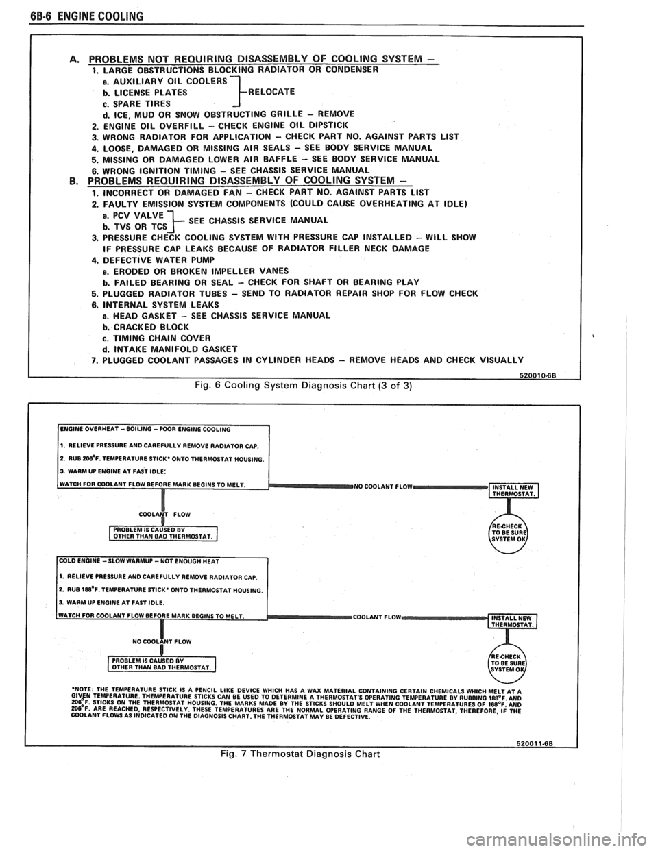
Fig. 6 Cooling System Diagnosis Chart (3 of 3)
1. RELIEVE PRESSURE AND CAREFULLY REMOVE RADIATOR CAP.
2. RUB W'F. TEMPERATURE STICK* ONTO THERMOSTAT MOUSING.
3. WARM UP ENGINE AT FAST IDLE:
WATCH FOR COOLANT FLOW BEFORE MAR
NO COOLANT FLOW INSTALL NEW
THERMOSTAT.
COLD ENGINE -SLOW WARMUP -NOT ENOUGH HEAT
1. RELIEVE PRESSURE AND CAREFULLY REMOVE RADIATOR CAP.
2. RUB 188'~. TEMPERATURE STICK' ONTO THERMOSTAT HOUSING.
3. WARM UP ENGINE AT FAST IDLE.
COOLANT FLOW
- 'NOTE: THE TEMPERATURE STICK IS A PENCIL LIKE DEVICE WHICH HAS A WAX MATERIAL CONTAINING CERTAIN CHEMICALS WHICH MELT AT A GIVEN TEMPERATURE THEWERATURE STICKS CAN BE USED TO DETERMINE A THERMOSTAT'S OPERATING TEMPERATURE BY RUBBING laB°F AN0 =OF. STICKS ON THE THERMOSTAT HOUSING. THE MARKS MADE BY THE STICKS SHOULD MELT WHEN COOLANT TEMPERATURES OF IWOF'AND W'F. ARE REACHED, RESPECTIVELY. THESE TEMPERATURES ARE THE NORMAL WERATING RANGE OF THE THERMOSTAT. THEREFORE, ~i WE COOLANT FLOWS AS INDICATED ON THE DIAGNOSIS CHART. THE THERMOSTAT MAY BE DEFECTIVE.
Fig. 7 Thermostat Diagnosis Chart