1988 PONTIAC FIERO ESP
[x] Cancel search: ESPPage 970 of 1825
DRIVEABILITY AND EMISSIONS - FUEL INJECTION 6E-9
ParWNelatral Switch IAC (Idle Air Control)
The indication in this mode may vary with This system is used to control engine idle speed to
manufacturer so the type of reading for a particular the desired rpm, for different operating conditions. In
tool should be checked in the operator's manual. The this mode, the numbers will indicate the position to
important thing is that the the reading changes state which
the ECM has moved the valve pintle. The ECM
(switches) when the gear selector is moved from moves
the IAC in counts, or steps, and the number of
paridneutral to drive or reverse. these counts are displayed on a "Scan" tool.
"Trque Convertor Clutch (TCC)
In this position, the tool will indicate when the
TCC has been commanded by the ECM to turn "ONJ'.
This does not necessarily mean that the clutch was
engaged but only that the
ECM grounded the circuit
internally. The best way to determine if the clutch has
engaged is to monitor engine rpm when the TCC
comes "ON".
EGR (Duty Cycle)
The EGR system uses a valve to feed a small
amount of exhaust gas back into the intake manifold
to control formation of NO,. Like all ECM outputs, the
"Scan" tool only indicates that the ECM has
commanded the function, and does not indicate that
the function has really happened.
EGR Position
This indicates the position of the EGR pintle.
Integrator and Block Learn
Normal readings for these positions are around
128. If higher, it indicates that the ECM is adding fuel
to the base fuel calculation because the system is lean,
and if the numbers are below 128, the ECM is taking
out fuel from the base calculation because the system
is rich. The integrator gives short term corrective
action, while the block learn portion (which is a long
term correction) will only change if the integrator has
seen a condition which lasts for a calibrated period of
time.
Block Learn Multiplier (BLM) Cell - or -
Block Learn Memory (BLM)
There are up to sixteen different cells,
corresponding to ranges of rpm and engine load
(indicated by MAF or MAP signals), and other
conditions, such as
A/C or P/N switch "ON" or "OFF",
etc. The ECM learns how much adjustment is needed
in each cell, and retains it in memory, so that the
adjustment will immediately be made when the
engine operates in that cell (or
rpmlload range). This
parameter will display what cell the ECM is currently
using for the fuel calculation.
Desired RPM
This indicates the rpm to which the ECM is trying
to control the idle.
Shift Light
This displays "yes" when the ECM is commanding
the shift light to turn "ON".
PPSW (Pump Prime Switch)
This is the voltage on the fuel pump feed circuit.
The ECM will adjust fuel injector base pulse width
from this voltage value rather than from battery
voltage.
NC Request
The state of the A/C signal line to the ECM is
shown. It should read "yes" whenever the
IVC is
requested.
NC Clutch
"ON" is displayed when the ECM has commanded
the
A/C clutch "ON".
Knock Retard
This indicates the number of degrees the ECM is
retarding the electronic spark timing (EST).
Knock Signal
This displays a "yes" when knock is detected by
the ECM, and a "no" when knock is not detected.
Battery Voltage
This displays the battery voltage detected at the
ECM ignition input.
Fan
"ON" is displayed when the cooling fan has been
commanded "ON".
Page 992 of 1825
HYDRAULIC DIAGNOSIS 700434-3
- The first to second gear shift point
- The second to third gear shift point
MANUAL SECOND (2)
2. With vehicle stopped, place gear selector in
"Second" (2) and accelerate to observe:
- The first to second gear shift point
3. Accelerate to 25 MPH (40 KPH) and observe:
- That a second to third gear shift does not
occur
- That TCC does not engage
MANUAL FIRST (I)
1. With vehicle stopped, place gear selector in
"First" (1) and accelerate to 15 MPH (24
KPH)
and observe:
- That no uoshift occurs
- That TCC does
REVERSE
1. With
vehicle stopped, place gear selector in
"Reverse" (R) and slowly accelerate to observe
reverse gear operation.
All possible throttle positions and corresponding
MPH shift point information has not been
provided.
TRANSMISSION PRESSURE CHECK
PROCEDURE
Inspect
e Fluid level
e TV cable adjustment
e Manual linkage
e Engine mechanical, emissions, electrical and fuel
delivery systems
not engage
Install or Connect (Figure 3)
a Oil pressure gage
a Tachometer
Page 1100 of 1825
AUTOMATIC TRANSMISSION 700-R4-49
--
NO. DESCRIPTION I 301 VALVE, T.V. MODULATOR DOWNSHIFT
302 SPRING, T.V. MODULATOR DOWNSHIFT
VALVE
303 VALVE, T.V. MODULATOR UPSHIFT
304 SPRING, T.V. MODULATOR UPSHIFT VALVE
305 SLEEVE, CONVERTER CLUTCH THROTTLE
306 SPRING, CONVERTER CLUTCH THROTTLE
307 VALVE, CONVERTER CLUTCH THROTTLE
308 VALVE, CONVERTER CLUTCH SHlFT
309 SLEEVE, 3-4 THROTTLE VALVE
3 10 SPRING, 3-4 THROTTLE VALVE
31 1 VALVE, 3-4 THROTTLE
312 VALVE, 3-4 SHlFT
31 3 SLEEVE, 2-3 THROTTLE VALVE
314 SPRING, 2-3 THROTTLE VALVE
31
5 VALVE, 2-3 THROTTLE
31 6 VALVE, 2-3 SHlFT
31 7 SLEEVE, 1-2 THROTTLE VALVE
31
8 SPRING, 1-2 THROTTLE VALVE
31 9 VALVE, 1-2 THROTTLE
322 VALVE, 1-2 SHlFT
323 SLEEVE, THROTTLE VALVE PLUNGER
324 PLUNGER, THROTTLE VALVE
325 SPRING, THROTTLE VALVE
326 VALVE, THROTTLE
328 VALVE, 3-4 RELAY
329 VALVE, 4-3 SEQUENCE
330 SPRING, 4-3 SEQUENCE VALVE
331 SPRING, T.V.
LIMIT VALVE
332 VALVE, T.V.
LIMIT
333 VALVE, 1-2 ACCUMULATOR
334 SLEEVE, 1-2 ACCUMULATOR VALVE
335 SPRING, 1-2 ACCUMULATOR VALVE
336 VALVE,
LlNE BlAS
337 SPRING, LlNE BlAS VALVE
338 SPRING, 3-2 CONTROL
339 VALVE, 3-2 CONTROL
340 VALVE, MANUAL
341 PIN, COILED SPRING
342 PIN, COILED SPRING
343 RETAINER, SPRING (SLEEVE)
344 PLUG, VALVE BORE
345 PLUG, CUP
(-33 DIA.)
346 SWITCH ASM., PRESSURE (3RD CLUTCH)
347 SWITCH ASM., PRESSURE (4-3 PULSE)
348 SWITCH ASM., PRESSURE
(4TH CLUTCH)
349 SWITCH ASM., PRESSURE
(T.C.C.
SIGNAL)
350 BODY, CONTROL VALVE
351 PLUG, T.V. LIMIT
352 PLUG, VALVE BORE (12.5
- O.D.)
354 PLUG, CONVERTER CLUTCH SHlFT VALVE
BORE
(ECM CONTROLLED VEHICLES)
355 PLUG, CONVERTER CLUTCH T.V. BUSHING
BORE
(ECM CONTROLLED VEHICLES)
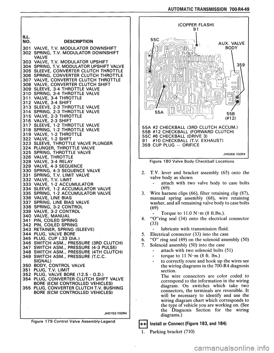
Figure 179 Control Valve Assembly-Legend
(COPPER FLASH) 9 1
55A
#2 CHECKBALL (3RD CLUTCH ACCUM.)
558 #12 CHECKBALL (FORWARD CLUTCH)
55C #6 CHECKBALL (DRIVE 3) 91 #10 CHECKBALL (T.V. EXHAUST)
359 CUP PLUG - ORIFICE
Figure 180 Valve Body Checkball Locations
2. T.V. lever and bracket assembly (65) onto the
valve body as shown
- attach with two valve body to case bolts
(69).
3. Wire harness
clips (66), filter retaining clip (87),
manual spring assembly (68), wire retaining
washer, and all remaining valve body to case bolts
(69) - Torque to 11.0 Nam (8 ft.lbs.).
4. "0"ring seal (34) onto the electrical connector
(33)
- lubricate with transmission fluid.
5. Electrical connector
(33) into the case
6.
"0" ring seal (49) on the solenoid assembly (50)
7. Solenoid assembly (50) into the case
- attach with two solenoid bolts (51)
- torque to 11 N . m (8 ft. lbs.)
- to correctly route and hook up the wires see
the wiring diagrams in the 700-R4 diagnosis
section.
The wire connectors are color coded to
correspond to the information in the wiring
diagram. On switches which take two
connectors, the terminals are reversible.
It
will be necessary to identify and use the
wiring diagram chart which corresponds to
the type
of vehicle you are working on. (See
the Diagnosis Section for the wiring
diagrams.)
Install or Connect (Figure 183, and 184)
1. Parking bracket (710)
Page 1169 of 1825
INTRODUCTION 1:
This manual contains the following kinds of
diagnostic information:
e Electrical Schematics
Component Location Lists
@ Harness Connector Faces
@ ?koubleshooting Hints
@ System Checks
System Diagnoses
@ Circuit Operation Descriptions
@ Harness Routing Views
Using these elements together will make elec-
trical troubleshooting faster and easier. Each
element is described below.
The Electrical
Seher~latic should always be
your starting point in using this Electrical
Troubleshooting Manual. The schematic shows
the electrical current paths when a circuit is
operating properly. It is essential to under-
stand how a circuit
should work before trying to
figure out why it doesn't.
The Harness Connector Faces show the cav-
ity or terminal locations in all the multi-pin
connectors shown in the schematic. Together
with the wire colors and terminals given in the
schematic, they help you locate test points. The
drawings show the connector faces you see
after the harness connector has been discon-
nected from a component. When more than one
connector is connected to a component the con-
nectors are all shown together.
The Troubleshooting Hints offer short-cuts
or checks to help you determine the cause of
a
complaint. They are not intended to be a rigid procedure
for solving an electrical situation.
Rather, Troubleshooting Nints represent a
common-sense approach, based on an under-
standing of the circuit.
The System Check gives a summary of how
the circuit should be operated and what should
happen. This is especially important when you
are working on a new system. The System
Check will help you identify symptoms, lead
you to diagnosis and confirm the system after
repair.
The System Diagnosis provides a procedure
to follow that will locate the condition in a cir-
cuit. If your own knowledge of the system and
the Troubleshooting Hints have not produced
a
quick fix, follow the System Diagnosis. All pro-
cedures are based on symptoms to assist you in
locating the condition as fast as possible.
The Circuit Operation will help you under-
stand the circuit. It describes the components
and how the circuit works.
The Component Location List helps you find
where the parts of the circuit are in the vehicle.
A brief statement of the location is given and
also a reference to a drawing that shows the
component and its connecting wires. These
Colnponent Location Views are in cell 201.
Harness Routing Views are found in cell 203.
These views show the routing of the major wir-
ing harnesses and the in-line connectors
between the major harnesses. These views will
make troubleshooting easier when you are not
sure about harness routing.
PAGE NUMBER
This section is organized into cells with most
cells containing a circuit schematic and the text
for that circuit. This makes the section easy to
use, since the page number for a schematic will
normally stay the same year after year, and it
will also be the same in
all the GM publications
about that circuit. For example, the Cruise Con-
trol schematics will always be the first pages of
cell 34. The other information for Cruise Con-
trol follows them on pages
34-2,34-3, etc.
Some cells may have more than one circuit
schematic, such as Power Distribution, Interior
Lights, and Air Conditioning. The circuit you
want can either be located by using the index, or
by a quick look through the related cell.
All the engine circuits for a particular engine
VIN type are in the same cell. This makes that
cell easy to use, since schematics for other cars
are not in your way. The instrument panel sche-
matics are organized similarly. If you are work-
ing on a car with a Digital Cluster, only the
schematics that apply to that car's Digital
Cluster will be in the cell you use. Information
on the Indicators and Gages Clusters will be in
other cells.
Page 1172 of 1825
INTRODUCTION
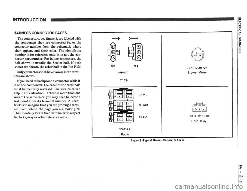
HARNESS CONNECTOR FACES
The connectors, see figure 3, are labeled with
the component they are connected to, or the
connector number from the schematic where
they appear, and their color. The identifying
number is for reference only; it is not the con-
nector part number. For in-line connectors, the
half shown is usually the Socket half. If both
views are shown, the other half is the Pin
Half.
Only connectors that have two or more termi-
nals are shown.
If you need to backprobe a connector while it
is on the component, the order of the terminals
must be mentally reversed. The wire color is a
help
in this situation. If there is more than one
wire of the same color, you may need to locate a
test point from its terminal number.
A useful
trick is to imagine that you are probing a termi-
nal from behind the page you are looking at.
Then mentally locate that terminal with respect
to the keyway or other reference mark.
v03000.2 Blower Motor
C3 BLU
C2 WHT
C1 BLK
v00010.0
Radio
BLU 12015196
Horn Relav
Figure 3 -Typical Harness Connector Faces
Page 1182 of 1825
TROUBLESHOOTING PROCEDURES
Step 2: Read the Headlights electrical sche-
matic, see figure
9. This is the step that will
save you time and labor. Remember, it is
essential to understand how a circuit
should
work, before trying to figure out why it
doesn't.
After you understand how the circuit should
operate, read the schematic again, this time
keeping in mind what you have learned by
operating the circuit.
Since both low beams work. you know that
the
Light Switch. the YEI, wire. the I,o con-
tacts of the Headlight Dimmer Switch. termi-
nal
1E of C100. the TAN wires. and grounds
6105 and G 109 are all good.
Furthermore, since you saw that the High
Beam Indicator came on when the Headlight
Dimmer Switch was moved to Hi. you know
that the Hi contacts of the
dimmer switch and
the
I,T GRN wire between the dimmer switch
and ClOO are good.
At this point. you could test for
voltage at
the RH Headlight with the dimmer switch in
Hi. However. it is extremely unlikely that the
high beam filaments have burned out in
both
headlights. or that both headlight connections
are bad. The cause must be a bad connection at
C100, or a break in the I,T GRN wire between
ClOO and the RH Headlight.
I,T GRN wire, locate the exact trouble point,
and make the repair.
Step 4: Check the repair by performing a sys-
tem check on the Headlights circuit. This, of
course, means making sure that both high
beams, both low beams, and the High Beam
Indicator are all working.
Now suppose that the symptoms were dif-
ferent. You may have operated the Headlights
and found that the low beams were working,
but neither the high beams nor the High Beam
Indicator were working. Looking at the sche-
matic, you might conclude the
following.
It is unlikely that both high beam filaments
and the High Beam Indicator have all burned
out at once. The cause is probably the dimmer
switch or its connector.
You have quickly narrowed the possible
causes down to one specific area, and have
done absolutely
no work on the car itself.
Step 3: Find the cause and repair it. Using the
Component Location List and the correspond-
ing figure. you can quickly find ClOO and the
Page 1187 of 1825
REPAIR PROCEDURES 0) B
ELECTRICAL REPAIRS
This section provides instruction in the fol-
lowing repairs:
- Circuit Protection
- Typical Electrical Repairs
- Splicing Copper Wire
- Splicing Aluminum \l.ire
- Splicing Txisted Shielded Cable
- Repairing Connectors (Except Weather
Pack
V and
- Repairing breather I'ack * (Environmen-
tal) Connectors
Note: After any electrical repair is made, always
test the circuit by operating the devices in the
circuit. This confirms not only that the repair is
correct, but also that the cause of the complaint
was correctly identified.
CIRCUIT PROTECTION
All electrical circuits are protected against
excessive loads which might occur because of
shorts or overloads in the wiring system. Such
protection is
prolrided by a fuse. circuit
breaker. or fusible link.
Fuses
The most common method of automotive
wiring circuit protection is the fuse. Whenever
there is an excessive amount of current flow-
ing through a circuit the fusible element will
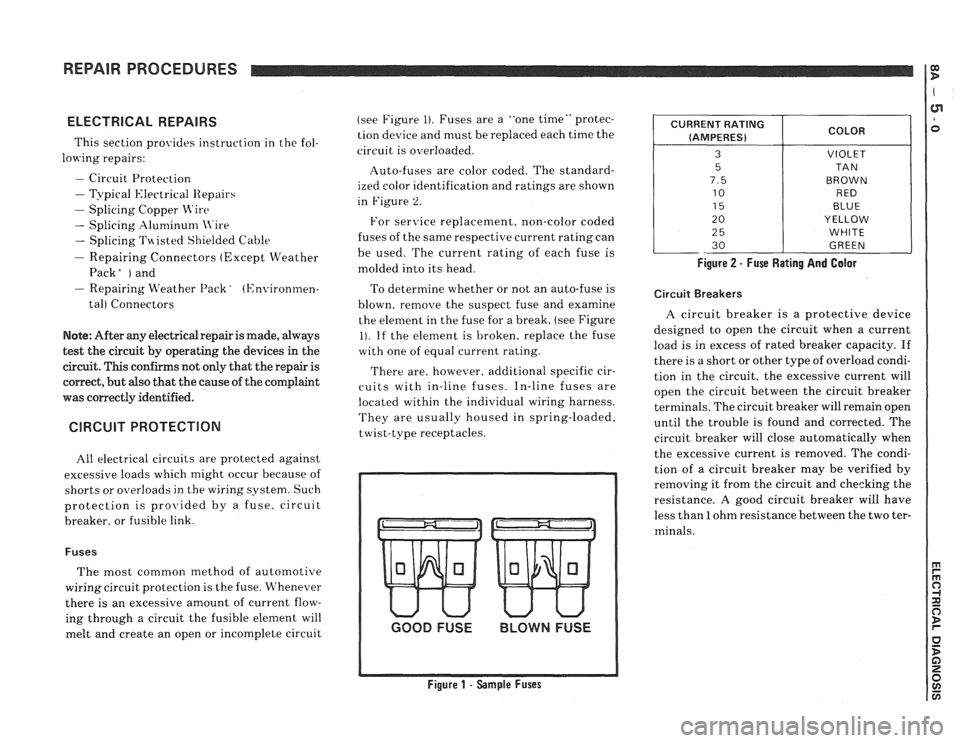
melt and create an open or incomplete circuit (see
Figure
1). Fuses are a "one time" protec-
tion device and must be replaced each time the
circuit is overloaded.
Auto-fuses are color coded. The standard-
ized color identification and ratings are shown
in Figure
2.
For senrice replacement. non-color coded
fuses of the same respective current rating can
be used. The current rating of each fuse is
molded into its head.
To determine whether or not an auto-fuse is
blown, remove the suspect fuse and examine
the element in the fuse for a break, (see Figure
1). If the element is broken, replace the fuse
with one of equal current rating.
There are, however. additional specific cir-
cuits with in-line fuses. In-line fuses are
located within the individual wiring harness.
They are usually housed in spring-loaded,
twist-type receptacles.
GOOD FUSE BLOWN FUSE
Figure 1 - Sample Fuses Figure
2 - Fuse Rating And Galor
CURRENT
RATING
(AMPERES)
3
5
7.5
10
15
20
2
5
30
Circuit Breakers
COLOR
VIOLET
TA N
BROWN RED
BLUE
YELLOW
WHITE
GREEN
A circuit breaker is a protective device
designed to open the circuit when a current
load is in excess of rated breaker capacity. If
there is a short or other type of overload condi-
tion in the circuit, the excessive current will
open the circuit between the circuit breaker
terminals. The circuit breaker will remain open
until the trouble is found and corrected. The
circuit breaker will close automatically when
the excessive current is removed. The condi-
tion of a circuit breaker may be verified by
removing it from the circuit and checking the
resistance.
A good circuit breaker will have
less than
1 ohm resistance between the two ter-
minals.
Page 1209 of 1825
POWER DISTRIBUTION
CIRCUIT OPERATION
Electrical power for the car is provided by the
Generator when the engine is running. The
schematic diagram shows how each circuit gets
its power. For more details about the Gener-
ator, and connections to the Battery and
Starter, see Starter and Charging System, Sec-
tion
8A-30.
The car's Power Distribution System con-
sists of Fusible Links, Fuses, Circuit Breakers,
the Light Switch and the Ignition Switch. Fusi-
ble Links are short pieces of wire to which they
supply power. They are covered with a special
high-temperature insulation. When conducting
a high current, the Fusible Link will melt and
stop current flow. They are designed to protect
the car's electrical system from electrical
shorts where it is not protected by the Circuit
Breakers and Fuses. See Fuse Block Details
and Light Switch Details for complete wiring to
the first component in each circuit.
The Ignition Switch has six positions, five of
which have detents. The BULB TEST position
is after the RUN position and just before the
START position. BULB TEST does not have a
detent. As shown in the schematic, circuits
which are supplied from the Ignition Switch are
On (Hot) for different switch positions. Indi-
vidual schematics show their fuses supplied
from headings such as "Not In Run. "The head-
ing corresponds to the Ignition Switch position
in which power is On.