1988 PONTIAC FIERO roof rack
[x] Cancel search: roof rackPage 102 of 1825

BUMPERS 28-1
SECTION 2B
BUMPERS
NOTICE: These fasteners are important attaching parts in that they could affect the performance of vital parts and
systems,
andlor could result in major repair expense. They must be replaced with one of the same part number or with an
equivalent
part if replacement becomes necessary. Do not use a replacement part of lesser quality or substitute design.
Torque values must be used as specified during reassembly to assure proper retention of all parts. There is to be no
welding as it may result in extensive damage and weakening of the metal.
NOTICE: The anti-theft label on some major sheet metal, engines, and transmissions must be masked prior to
painting, rustproofing, undercoating, etc. The mask MUST be removed following the above operations. Failure to keep
the label clean and readable may result in liability for violation of Federal Vehicle Theft Prevention Standard, and subject
the vehicle owner to possible suspicion that the part was stolen.
CONTENTS
General Description ................................ 2B-1 On-Vehicle Service ..................................... 2B-4
........................................... ..................... Service Procedures .. ........... 2B- 1 Specifications 2B-5
GENERAL DESCRIPWIBN
The bumpers on all Pontiac automobiles are remover.
Install new tape (double-coated neoprene
designed so that the vehicle can withstand a collision foam type)
to the back side of the rub strip.
into a fixed barrier at
5 mph. After absorbing the
energy of a collision, the bumpers restore themselves After
rub strip is installed, roll along entire
to their original position. surface with a roller
in order to insure a good bond.
The front and rear bumper fascias are made of
urethane. Urethane will withstand minor impact and
return to its original shape. Some front bumper fascias
are integral with the front end panel.
Some models use both steel and aluminum
bumper reinforcements. Usage is based on
EPA weight
class requirements.
BUMPER FASCIA RUB STRIPS
Some front and rear fascia rub strips are made of
a shiny plastic material. If a rub strip of this type loses
its lustre, the original shine can be restored by using
GM Plastic Cleaner or its equivalent. Follow directions
on the label.
SERVICE PROCEDURES
RUB STRIPS
Remove and Replace
Some plastic rub strips have an adhesive tape
backing (similar to a body side molding) and some have
studs or retaining tabs. In order to properly remove the
adhesive tape and avoid paint damage to the fascia, use
either a release agent or a heat lamp to soften the bond
of the adhesive tape to the fascia. In some cases, it will
be necessary to replace the rub strip with a new rub
strip instead of reusing the old one.
If the old rub strip is salvagable, remove all tape
from the back side of the rub strip as previously
described. Wipe strip clean with a wax and adhesive
FRONT BUMPER FASCIA (FRONT END PANEL)
Removal
Place a jack stand under fascia assembly before
removing bolts to prevent it from dropping down when
fascia attaching bolts are removed. Fascia will pivot on
the opposite end when one end is disconnected. Do not
rotate energy absorber any more than necessary to
align mounting holes.
1. Remove fascia attaching bolts and fascia to
fender attaching screws on right and left side, and
remove fascia and spacers.
2. If energy absorber is to be replaced, remove the
bolts and nuts from the front of the unit and the
nut from the stud at the rear.
Installation
1. Install energy absorber if removed.
2. Support fascia during installation to prevent
rotation of energy absorbers.
3. Install spacers and bolts at fascia to energy
absorber brackets.
4. Install fascia to fender attaching screws.
5. Check for proper clearance.
6. If adjustment is required to align fascia, loosen
energy absorber mounting bolts and position as
required (holes are slotted). Adjustment side to
side can be made by loosening fascia bracket
bolts. Torque all bolts and nuts. (See
Specifications.)
Page 1760 of 1825

ROOF - F STYLE 8H-1
SECTION 8H
ROOF
CONTENTS
Formed Headlining .......................................... 8H- 1
Interior Roof Attachments
.............................. 8H- 1
Interior Garnish Moldings .............................. 8H-2
Exterior Roof Moldings and
Attachments
.................................... .... ... 8H-3
Twin Lift-off Panel
......................................... 8H-3
Convertible Top
Top Operation
............................................ 8H-7
Header Inner Garnish
................................. 8H-8
"A" Pillar Inner Garnish
........... .;. .............. 8H-9
Header
"A" Pillar Seal ................................ 8H-9
Side Rail Seal and Retainer
......................... 8H-9
Main Pillar Seal and Retainer
..................... 8H-9
No.
5 Bow Seal .......................................... 8H-9
No. 1 Bow Garnish Molding
....................... 8H-9
Top Cover Assembly
.................................... 8H- 1 1
Side Stay Pads ............................................. 8H-13
Rear Stay Pads ............................................ 8H- 13
No.
1 and No. 2 Bows ................................. 8H- 13 NO. 3
BOW
.................................................... 8H-15
NO. 4 BOW ................................................ 8H-15
NO. 5 BOW ................................................. 8H-15
Top Stack Assembly Complete .................... 8H- 16
Quarter Inner Upper Trim Cap
.................. 8H- 17
Quarter Trim Panel
.................................... 8H- 17
Quarter Cap Belt Molding
........................... 8H- 17
Tonneau Panel Latch
................................. 8H- 17
Tonneau Release Solenoid
........................... 8H- 17
No. 5 Bow Release Handle
.......................... 8H- 19
No.
5 Bow Latch ....................................... 8H-19
Tonneau Panel
.......................................... 8H- 19
Tonneau Panel Seal
............................. ......... 8H-20
Deck Lid Spoiler ........................................ 8H-2 1
Center High Mount Stop Lamp .................. 8H-21
Deck Lid .................................................... 8H-21
Deck Lid Panel Seal
................................. 8H-22
Door Cap Belt Molding ............................... 8H-22
Front Belt Retractor Assembly ................... 8H-22
FORMED HEADLINING 1. Load the headlining through the rear
The one-piece formed headlining (Fig. 1) consists
of a molded fiberglass substrate covered with a foam
and cloth facing. The one-piece construction requires
the headlining be serviced as a complete assembly.
The headlining is held partially in place by
retaining fasteners located in the headlining which fit
into slots in the roof panel. Final attachment is
accomplished when the interior moldings and
attaching screws that retain the sunshade brackets,
dome lamp base and coat hooks are installed.
Removal
1. Remove the following items:
e Back body opening upper garnish molding
r Windshield side upper garnish molding (1,
Fig. 3 or
6)
e Rear vertical garnish molding
a Windshield header courtesy reading and
console lamp
e Sunshades
e Partially remove shoulder belt bezel and
belt
a Coat hooks and rail panel inserts
2. Grasp headlining assembly with both hands at
outer edges and move to the right of centerline to
disengage fastener assemblies from front
attaching slots.
3. Remove headlining assembly through right front
door.
lnstallation
Care must be exercised when loading assembly.
Excessive flexing may result in damage. compartment
opening.
2. Align headlining with cutouts for sunshades and
dome lamp and install sunshade brackets and
dome lamp base. Do not tighten sunshade bracket
and dome lamp attaching retainers completely
until headlining is aligned properly at all
hardware attaching locations.
3. Align headlining to roof inner panel with
fasteners positioned over holes in roof panel and
using palm of hand, push up on headlining at
fastener locations.
4. Install all previously removed hardware and
interior moldings.
INTERIOR ROOF ATTACHMENTS
DOME LAMPS
The dome lamp operates in conjunction with the
door jamb switch and/or the
headlamp switch. The
dome lamp harness extends up the right windshield
pillar, outboard of the sunshade support and across the
roof inner panel to the dome lamp.
Removal and Installation (Typical)
1. Grasp lens portion of dome lamp assembly,
squeeze and pull down to remove.
2. Remove bulb from terminal clips.
3. Remove retainers from studs.
4. Disengage wire harness from lamp housing and
remove dome lamp housing.
5. To install dome lamp assembly, reverse removal
procedure.
Page 1772 of 1825

@ -
ROOF - F STYLE 8N-13
7. Rear stay pad and side stay pad from No. 4 bow
by sliding off.
Install or Connect
1. Side
stay pad and rear stay pad onto the No. 4
bow.
2. Screws
3. Rivet using
1/8" x 3/16" aluminum rivet.
4. Position side stay
pad to No. 1 bow and install
rivets using
1/8" x 3/16" aluminum rivets.
5. Tape (7)
6. With top
latched to windshield header and No.
Fig. 14 No. 1 Bow Garnish Molding 5 bow latched to tonneau panel, staple side stay
pad to No. 2 and No. 3 bows using 5/16" x 5/16"
stainless steel staplea. -
20. Release
and raise the tonneau panel to its full 7. Top cover assembly (see procedure). vertical position.
Release and raise the tonneau panel to its full
vertical position.
Lower the No,
5 bow to its original position.
Unlatch the top from
8-e windshield header and
lower the top halfway.
Apply adhesive such as Hughes HC-4183,
3M
8046 or equivalent to cementing area of No. 1
bow and to corresponding surface of top cover
and flaps.
Pull top cover 6 mm
(1/4") past reference mark
over No. 1 bow and secure top to No. 1 bow
starting at center working toward outboard ends.
Raise and latch top
*o windshield header and
latch No. 5 bow tu tonneau panel. Check
appearance of top cover, top
opeation and
latching effort to top. If additional tension is
needed in top cover, repeat step 25 and pull top
cover farther forward.
.
Trim off excess material along No. 1 bow.
Main pillar seal retainers.
Screws (5)
Apply continuous bead of 3M Super
Weatherstrip Adhesive, part number 08008 or
equivalent to the retainer channels.
Main pillar seals using a flat-bladed tool, engage
seal into retainer.
32. Side
rail seal and retainer assemblies
33. Screws (2)
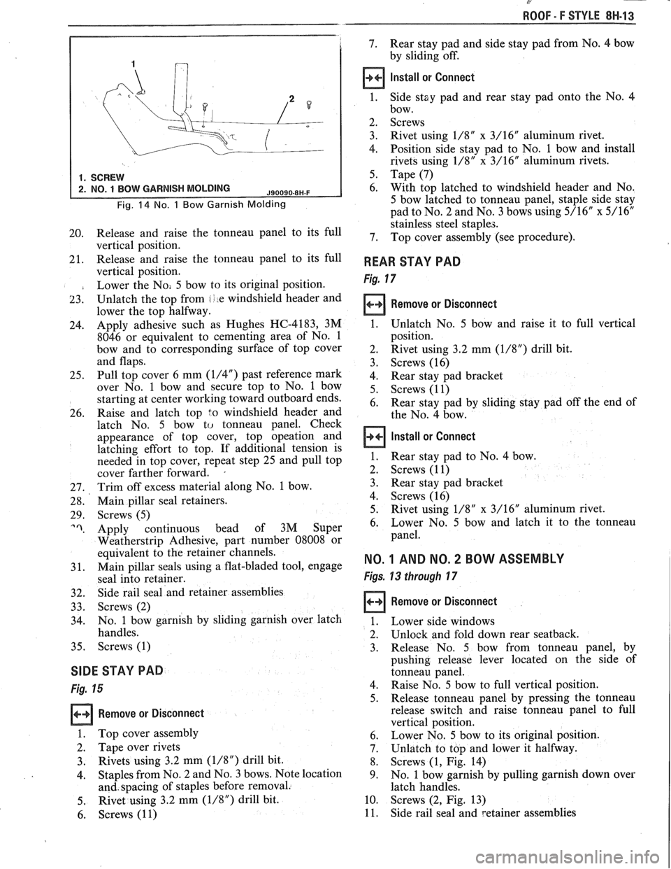
34. No. 1
bow garnish by sliding garnish over latch
handles.
35. Screws (1)
SIDE STAY PAD
Fig. 15
Remove or Disconnect
1. Top cover assembly
2. Tape over rivets
3. Rivets using 3.2 mm (1/8") drill bit.
4. Staples from No. 2 and No. 3 bows. Note location
and. spacing of staples before removal.
5. Rivet
using 3.2 mm
(1/8") drill bit.
6. Screws
(1 1)
REAR STAY PAD
Fig. 17
Remove or Disconnect
1. Unlatch No. 5 bow and raise it to full vertical
position.
2. Rivet using
3.2 mm
(1/8") drill bit.
3. Screws (16)
4. Rear stay pad bracket
5. Screws (1 1)
6.
Rear stay pad by sliding stay pad off the end of
the No. 4 bow.
Install or Connect
1. Rear
stay pad to No. 4 bow.
2. Screws (1 1)
3. Rear stay pad bracket
4. Screws (16) 5. Rivet
using
1/8" x 3/16" aluminum rivet.
6. Lower No.
5 bow
and latch it to the tonneau
panel.
NO. 1 AND NO. 2 BOW ASSEMBLY
Figs. 13 through 17
Remove or Disconnect
Lower side windows
Unlock and fold down rear seatback.
Release No. 5 bow from tonneau panel, by
pushing release lever located on the side of
tonneau panel.
Raise No. 5 bow to full vertical position.
Release tonneau panel by pressing the tonneau
release switch and raise tonneau panel to full
vertical position.
Lower No. 5 bow to its original position.
Unlatch to top and lower it halfway.
Screws (1, Fig. 14)
No. 1 bow garnish by pulling garnish down over
latch handles.
Screws
(2, Fig. 13)
Side rail seal and setainer assemblies
Page 1775 of 1825

C
8H-16 ROOF - F STYLE
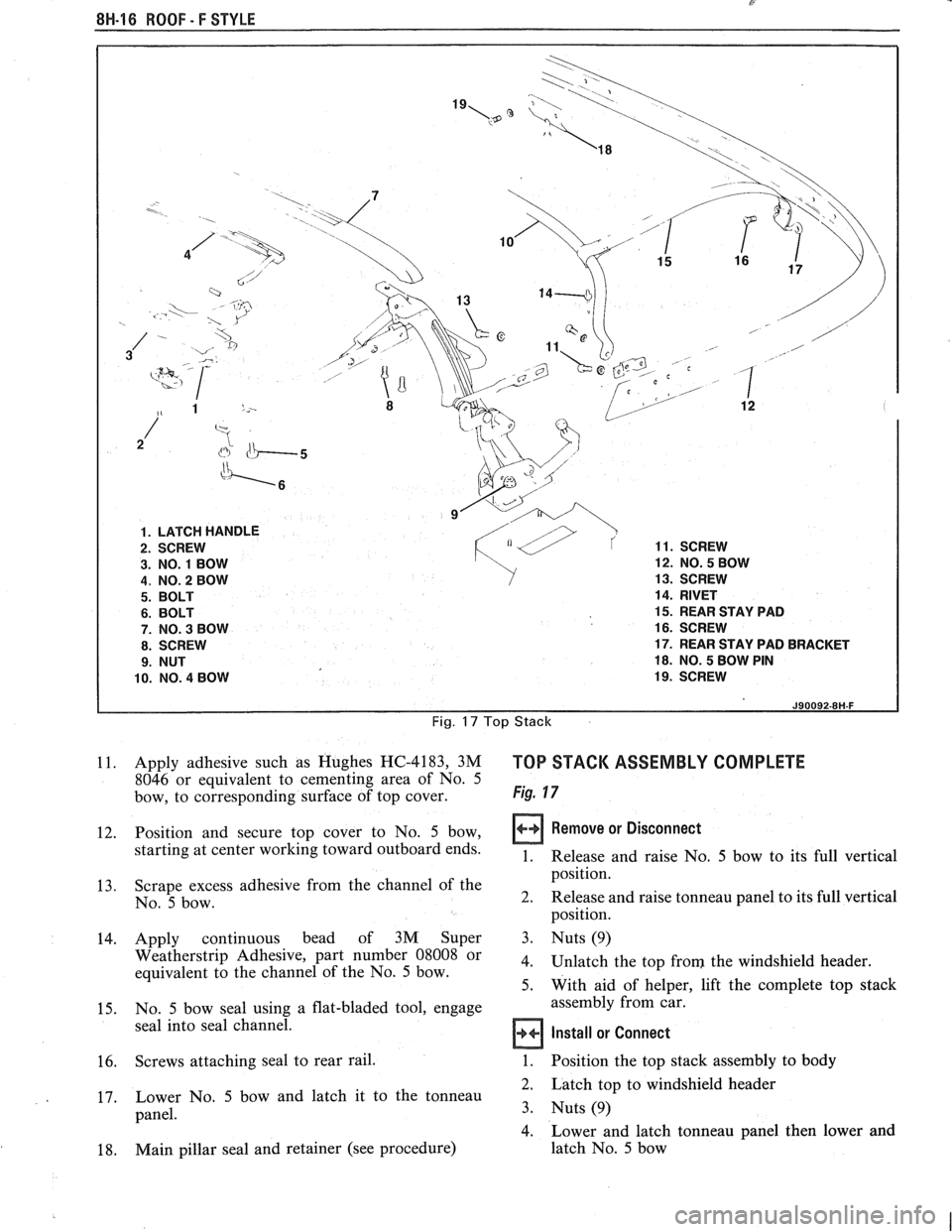
1. LATCH HANDLE
3. NO.
1 BOW 12.
NO. 5 BOW
4, NO. 2 BOW 13.
SCREW
14. RIVET
15. REAR STAY PAD
16. SCREW
17. REAR STAY PAD BRACKET
18. NO. 5 BOW PIN
10. NO. 4 BOW 19.
SCREW
Fig. 17 Top Stack
11. Apply adhesive such as Hughes HC-4183, 3M TOP STACK ASSEMBLY COMPLETE 8046 or equivalent to cementing area of No. 5
bow, to corresponding surface of top cover. Fig. 7 7
12. Position
and secure top cover to No. 5 bow, Remove or Disconnect
starting at center working toward outboard ends. Release and raise No, bow to its full vertical
position.
13. Scrape
excess adhesive from the channel of the
No.
5 bow. 2.
Release
and raise tonneau panel to its full vertical
position.
14. Apply continuous bead of
3M Super 3. Nuts (9)
Weatherstrip Adhesive, part number Ogoo8 Or 4. Unlatch the top from the windshield header. equivalent to the channel of the No. 5 bow. 5. With aid of helper, lift the complete top stack
15. No.
5 bow
seal using a flat-bladed tool, engage assembly
from car.
seal into seal channel.
Install or Connect
16. Screws attaching seal to rear rail. 1. Position the top stack assembly to body
2. Latch top to windshield header
17. Lower
No.
5 bow and latch it to the tonneau
panel.
3. Nuts(9)
4. Lower and latch tonneau panel then lower and
18. Main
pillar seal and retainer (see procedure) latch
No. 5 bow