1988 PONTIAC FIERO radio
[x] Cancel search: radioPage 1555 of 1825
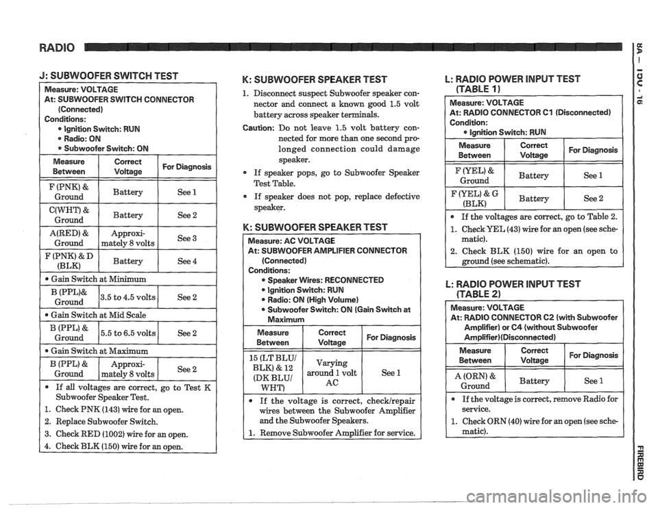
J: SUBWOOFER SWITCH TEST
At: SUBWOOFER SWITCH CONNECTOR
lgnition Switch: RUN
. Radio: ON
* Subwoofer Switch: ON
Measure Correct
I Voltage I For Diagnosis
Between
I F(PNK'& I Battery / See 1 I Ground
I C(WHT" I Battery / See2 1 Ground
I (P,","ip" 1 Battery 1 See 4 I
A(RED) &
Ground
I 0 Gain Switch at Minimum I
Approxi-
mately
8 volts
I * Gain Switch at Mid Scale 1
See 3
(PPL'&
Ground
1 (PPL'& 15.5 to 6.5 volts / See 2 I Ground
3.5 to 4.5 volts
1. Check PNK (143) wire for an open.
2. Replace Subwoofer Switch.
3. Check RED (1002) wire for an open. See
2
I
I
* Gain Switch at Maximum
K: SUBWOOFER SPEAKER TEST
1. Disconnect suspect Subwoofer speaker con-
nector and connect a
known good 1.5 volt
battery across speaker te
B (PPL)
&
Ground
Caution: Do not leave 1.5 volt battery con-
nected for more than one second pro-
longed connection could damage
speaker.
If speaker pops, go to Subwoofer Speaker
Test Table.
If speaker does not pop, replace defective
speaker.
K: SUBWOOFER SPEAKER TEST
If all voltages are correct, go to Test K
Subwoofer Speaker Test.
Approxi-
mately 8 volts
lFlER CONNECTOR
* Speaker Wires: RECONNECTED
lgnition Switch: RUN
* Radio: ON (High Volume)
0 Subwoofer Switch: ON (Gain Switch at
If the voltage is correct, checklrepair
wires between the Subwoofer Amplifier
and the Subwoofer Speakers.
See
2
L: RADlO POWER INPUT TEST
(TABLE
11
Measure: VOLTAGE
At: RADIO CONNECTOR
Cl (Disconnected)
Condition:
Measure Correct
I Voltage I For Diagnosis
Between
I Ground IYEL'& I Battery I See 1
F(YEL' &G I Battery (BLK) See 2
0 If the voltages are correct, go to Table 2.
1. Check UEL (43) wire for an open (see sche-
matic).
2. Check BLK
(150) wire for an open to
L: RADIO POWER INPUT TEST
(TABLE
2)
Measure: VOLTAGE
At: RADIO CONNECTOR
62 (with Subwoofer
Amplifier) or
64 (without Subwoofer
Amplifier)(Disconnected)
Measure Correct
For Diagnosis
Between
Voltage
I A (ORN) & I Battery I See l ( Ground
* If the voltage is correct, remove Radio for
service.
1. Check ORN (40) wire for an open (see sche-
matic).
Page 1556 of 1825
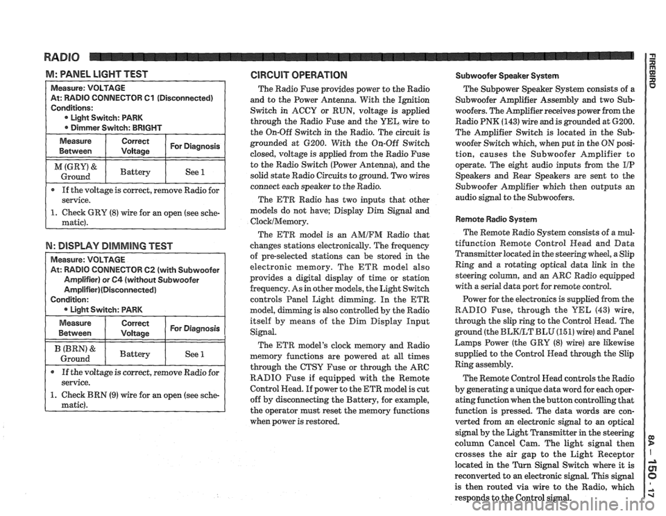
M: WNEL LIGHT TEST GlRGUlT OPERATION Subwoofer Speaker System
TOR 61 (Disconnected)
If the voltage is correct, remove Radio for
N: DISPLAY DIMMING TEST
TOW 62 (with Subwoofer
The Radio Fuse provides power to the Radio
and to the Power Antenna. With the Ignition
Switch in ACCY or RUN, voltage is applied
through the Radio Fuse and the
UEL wire to
the On-Off Switch in the Radio. The circuit is
grounded at 6200. With the On-Off Switch
closed, voltage is applied from the Radio Fuse
to the Radio Switch (Power Antenna), and the
solid state Radio Circuits to ground. Two wires
connect each speaker to the Radio.
The ETR Radio has two inputs that other
models do not have; Display Dim Signal and
ClocklMemory.
The ETR model is an AMIFM Radio that
changes stations electronically. The frequency
of pre-selected stations can be stored
in the
electronic memory. The ETR model also
provides a digital display of time or station
frequency. As in other models, the Light Switch
controls Panel Light dimming. In the
ETR
model, g is also controlled by the Radio
itself by means of the Dim Display Input
Signal.
The ETR model's clock memory and Radio
memory functions are powered at all times
through the CTSY Fuse or through the ARC
RADIO Fuse if equipped with the Remote
Control Head. If power to the ETR model is cut
off by disconnecting the Battery, for example,
the operator must reset the memory functions
when power is restored. The
Subpower Speaker
System consists of a
Subwoofer Amplifier Assembly and two Sub-
woofers. The Amplifier receives power from the
Radio PNK
(143) wire and is grounded at 6200.
The Amplifier Switch is located in the
Sub-
woofer Switch which, when put in the ON posi-
tion, causes the Subwoofer Amplifier to
operate. The eight audio inputs from the
I/P
Speakers and Rear Speakers are sent to the
Subwoofer Amplifier which then outputs an
audio signal to the Subwoofers.
Remote Radio System
The Remote Radio System consists of a mul-
tifunction Remote Control
Head and Data
Transmitter located in the steering wheel, a Slip
Ring and a rotating optical data link in the
steering
colurnn, and an ARC Radio equipped
with a serial data port for remote control.
Power for the electronics is supplied from the
RADIO Fuse, through the
YEL (43) wire,
through the slip ring to the Control Head. The
ground (the
BLKLT BLU (15 1) wire) and Pand
Larnps Power (the GRY (8) wire) are Likewise
supplied to the Control Head through the Slip
Ring assembly.
The Remote Control Head controls the Radio
by generating a unique data word for each oper-
ating function when the button controlling that
function is pressed. The data words are con-
verted from an electronic signal to an optical
signal by the Light Transmitter in the steering
column Cancel Cam. The light signal then
crosses the air gap to the Light Receptor
located in the
Turn Signal Switch where it is
reconverted to
an electronic signal. This signal
is then routed via wire to the Radio, which
responds to the Control signal.
Page 1558 of 1825
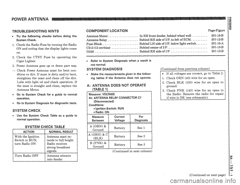
POWER ANTENNA
TROUBLESHOOTING HINTS
r Try the following checks before doing the
System Check.
1. Check the Radio Fuse by turning the Radio
ON and noting that the display lights come
on.
2. Check the CTSY Fuse by operating the
Cigar Lighter.
3. Power Antenna goes up or down part way
- Check Power Antenna mast for bent con-
dition or dirt. If
mast is dirty and/or bent,
straighten the mast and clean off the dirt.
Lube with light oil and check operation. If
the mast is straight and clean, replace the
Antenna Motor.
c Go to System Check for a guide to normal
operation.
e Go to System Diagnosis for diagnostic tests.
SYSTEM CHECK
a Use the System Check Table as a guide to
normal operation.
SYSTEM CHECK '6ABLE
Radio receives
COMPONENT LOCATION Page-Figure
................. ......... Antenna Motor. In RW front fender, behind wheel well 201-16-B
.................. .......... Antenna Relay Behind RN side of I/P, to
left of ECM 201-12-B
..................... ...... Fuse Block. Behind LR side
of UP, below light switch. 201-10-A
........................ ................ 6212 (12 cavities) Behind center of I/P 201-13-B
...................... .......................... 6320 Behind RH side of IIP 201-12-33
Refer to System Diagnosis when a result is
not normal.
SYSTEM DlAGNOSlS
o Make the measurements given in the follow-
ing tables if the Antenna does not operate.
A: ANTENNA DOES MOT OPERATE
(TABLE 1)
At: ANTENNA RELAY CONNECTOR 61
(Continued in next column) Continued
from previous
column)
2. Check BLK (150) wire for an open to
ground.
3. Check PNK (143) wire for an open to
the Radio. Remove the radio for repair
(Continued on next page)
Page 1559 of 1825
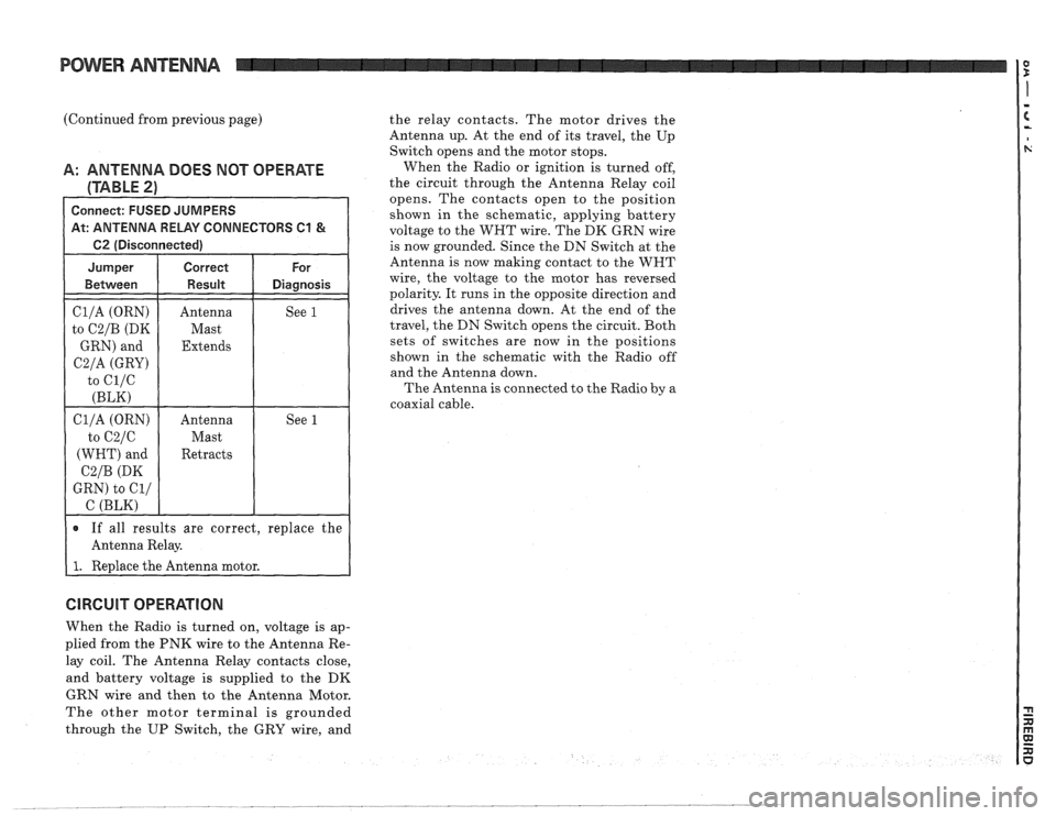
POWER ANTENNA
(Continued from previous page) the relay contacts. The motor drives the
Antenna up. At the end of its travel, the Up
Switch opens and the motor stops.
A: ANTENNA DOES NOT OPERATE When the Radio or ignition is turned off,
(TABLE 2) the circuit through the Antenna Relay coil
opens. The contacts open to the position
Connect: FUSED JUMPERS shown in the schematic, applying battery At: ANTENNA RELAY CONNECTORS C1 & voltage to the WHT wire. The DK GRN wire
1 62 (Disconnected) I
Cl/A (ORN)
to
C2/B (DK
GRN) and
C2/A (GRY)
to ci/c
(BLK)
Antenna
Mast
Extends See 1
If all results are correct,
replace the
Antenna Relay.
I 1. Redace the Antenna motor. is
now grounded.
Since the DN Switch at the
Antenna is now making contact to the WNT
wire, the voltage to the motor has reversed
polarity. It runs in the opposite direction and
drives the antenna down. At the end of the
travel, the DN Switch opens the circuit. Both
sets of switches are now in the positions
shown in the schematic with the Radio off
and the Antenna down.
The Antenna
is connected to the Radio by a
coaxial cable.
CIRCUIT OPERATION
When the Radio is turned on, voltage is ap-
plied from the PNK wire to the Antenna Re-
lay coil. The Antenna Relay contacts close,
and battery voltage is supplied to the
DK
GRN wire and then to the Antenna Motor.
The other motor terminal is grounded
through the UP Switch, the GRY wire, and
Page 1585 of 1825
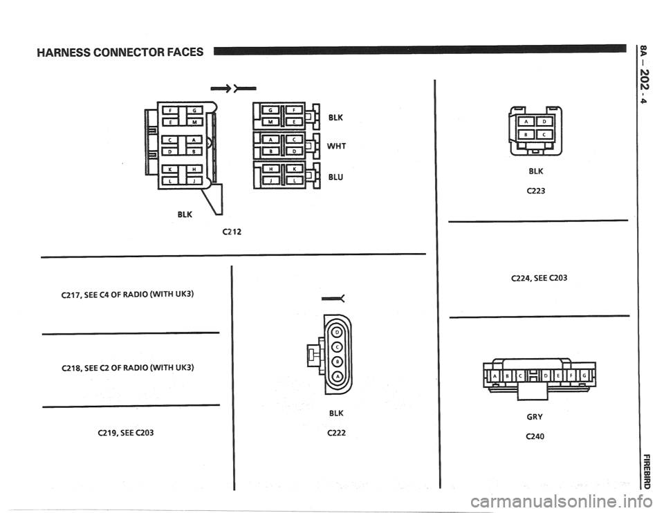
HARNESS CONNECTOR FACES If
BLK
WHT
BLU
BLK
C217, SEE C4 OF RADIO (WITH UK3)
C218, SEE C2 OF RADIO (WITH UK3)
C219, SEE C203 BLK BLK
C223
C224, SEE C203
Page 1593 of 1825
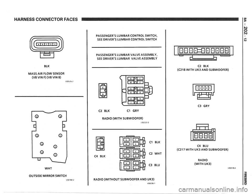
HARNESS CONNECTOR FACES
BLK
MASS AIR FLOW SENSOR
(V8 WIN F) (V8 WIN 8)
V00526.2
WHT
OUTSIDE MIRROR SWITCH
V00184 2
PASSENGER'S LUMBAR CONTROL SWITCH,
SEE DRIVER'S LUMBAR CONTROL SWITCH
, PASSENGER'S LUMBAR VALVE ASSEMBLY,
1 SEE DRIVER'S LUMBAR VALVE ASSEMBLY
C2 BLK C1 CRY
RADIO (WITH SUBWOOFER)
~00320 0
C4 BLK
C1 BLK
C2 WHT
C3 BLU
RADIO (WITHOUT SUBWOOFER AND
UK3)
V00236 1
C2 BLK
(C218 WITH UK3 AND SUBWOOFER)
C4 BLU
(C217 WITH UK3 AND SUBWOOFER)
RADIO
(WITH UK3)
V00578.0
Page 1594 of 1825
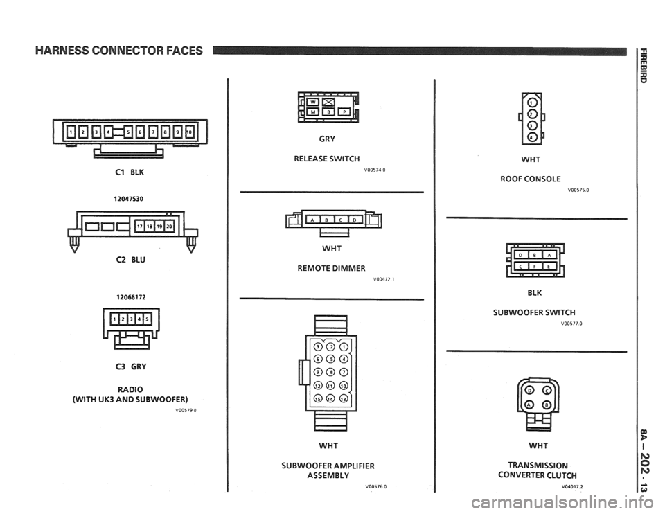
HARNESS CONNECTOR FACES
C1 BLK
12047530
C2 BLU
CRY
RELEASE SWITCH
WHT
REMOTE DIMMER
V00412 1
C3 GRY
RADIO
(WITH UK3 AND SUBWOOFER)
V00579 0
SUBWOOFER AMPLIFIER
ASSEMBLY
V00576.0
WHT
ROOF CONSOLE
V00515.0
BLK
SUBWOOFER SWITCH
V00577.0
WHT
TRANSMISSION
CONVERTER CLUTCH
V040 17.2
Page 1612 of 1825
INSTRUMENT PANEL, GAGES & CONSOLE 8C-'I
SECTION 8C
NSTRUMENT PANEL, GAGES & CONSOLE
CONTENTS
General Description ................................... 8C-1
Instrument Panel and Gages ........................ 8C-1
Printed Circuit .......................................... 8C-1
Instruments ................................................... 8C- 1
Speed Sensors
............................ .. ............. 8C- 1
Pinion Gear
............................................. 8C-2
Photo Speed Sensor ................................ 8C-2
PM Generator ................... .. ...... ............... 8C-2
Speedometer ................................................ 8C-2
Mechanical ....................... .. .................... 8C-2
Quartz ........................ .. .......................... 8C-2
Digital .................... .. ...... ................. 8C-2
Fuel Gage .................................................... 8C-2
Temperature Warning Light ...................... 8C-3
Generator Warning Light ............................ 8C-3
Engine Oil Pressure Light ............................ 8C-3
"Service Engine Soon" Light ....................... 8C-3
Upshift Indicator Light .............................. 8C-3
Diagnosis .................... .. ........................... 8C-3
General Information .................................. 8C-3
Instrument Panel & Gages ...................... ..... 8C-3
On-Car Service ......................... .. ........... 8C-4
Instrument Panel Pad ................................... 8C-4
Instrument Panel Cluster ........................... 8C-4
Instrument Panel Carrier ............................. 8C-4
Headlight Switch .......................................... 8C-4
Console Mounted Switches and
Accessories
............................................... 8C-4
Console ......................................................... 8C-4
Speedometer .................................................. 8C-5
Illustra3ions ................................................. 8C-5
IP Pad ........................................................... 8C-5
IP Carrier ................................................... 8C-6
Instrument Cluster ....................................... 8C-6
Lower IP Covers ......................................... 8C-7
IP Trimplates ............................................... 8C-7
IP Hush Panels; with A/C .......................... 8C-8
..................... IP Lower Trim Pad (Console) 8C-8
Map Holder or Map Pocket ........................ 8C-8
IP Hush Panels; without A/C ..................... 8C-9
Radio Mounting ........................................... 8C-9
Subwoofer & Hatch Release
Switches/Covers ........................................ 8C- 10
Foglamp Switch/Cover ................................ 8C- 10
Oil Pressure and Temperature
Switches
..................................................... 8C-11
Heater/Ventilation/Defroster
Ductwork .................................................. 8C- 12
A/C and Defroster Ductwork ..................... 8C-13
Ram Vent System Ductwork ....................... 8C-14
Console Mounted Switches
&
Accessories ................................................. 8C- 14
Dash Insulators
............................................ 8C- 15
Heater Floor Outlet
..................................... 8C-15
................ Headlamp/Parking Lamp Switch 8C- 15
............. Dash Mounted Accessory Switches 8C- 15
GENERAL DESCRIPTION
INSTRUMENT PANEL AND GAGES
INSTRUMENTS
Instruments consist of fuel gage, temperature
The instrument panel on most cars is a sing,e unit indicator light, generator light, oil pressure indicator
design and all parts attach to the main instrument light, and speedometer. See Section 9F for optional
panel with clips and screws. To service the instrument Gages and tachometer. Service on instruments
panel and components see on-car service information, can be obtained through authorized repair stations.
However, knowledge of instrument circuit checks will
PRINTED CIRCUIT
All models are equipped with printed circuits
which supply current to most instrument panel lights
and instruments. These circuits are made of copper foil
which is die cut and bonded to a polyester base film
(usually mylar). The printed circuit electrical power is
supplied by a connector containing several wires, as
shown in the instrument panel wiring harness
installation instructions. The connector also helps
retain the printed circuit to the speedo cluster. The rest
of the circuit is retained by additional connectors (if
used) and snap-in
bulbs/sockets. For individual
printed circuit diagrams, see Section
8A-80/8 1/82/83,
'Instrument Panel'. help
in determining if operating difficulties lie in the
instrument itself or its related circuit.
Instruments have been designed for easy removal
by elimination of separate wiring. With the wiring
provisions integrated with the instrument panel wiring,
the instruments can be removed after removing the
trim and lens.
SPEED SENSORS
There are three speed sensors currently in use:
1. PINION GEAR; used in mechanical systems
2. PHOTO SPEED SENSORS; used in mechanical
systems
3. PM GENERATOR; used in electronic systems