1988 PONTIAC FIERO radio
[x] Cancel search: radioPage 711 of 1825
6E3-B-2 2.8L (VIN 5) DRIVEABILITY AND EMISSIONS
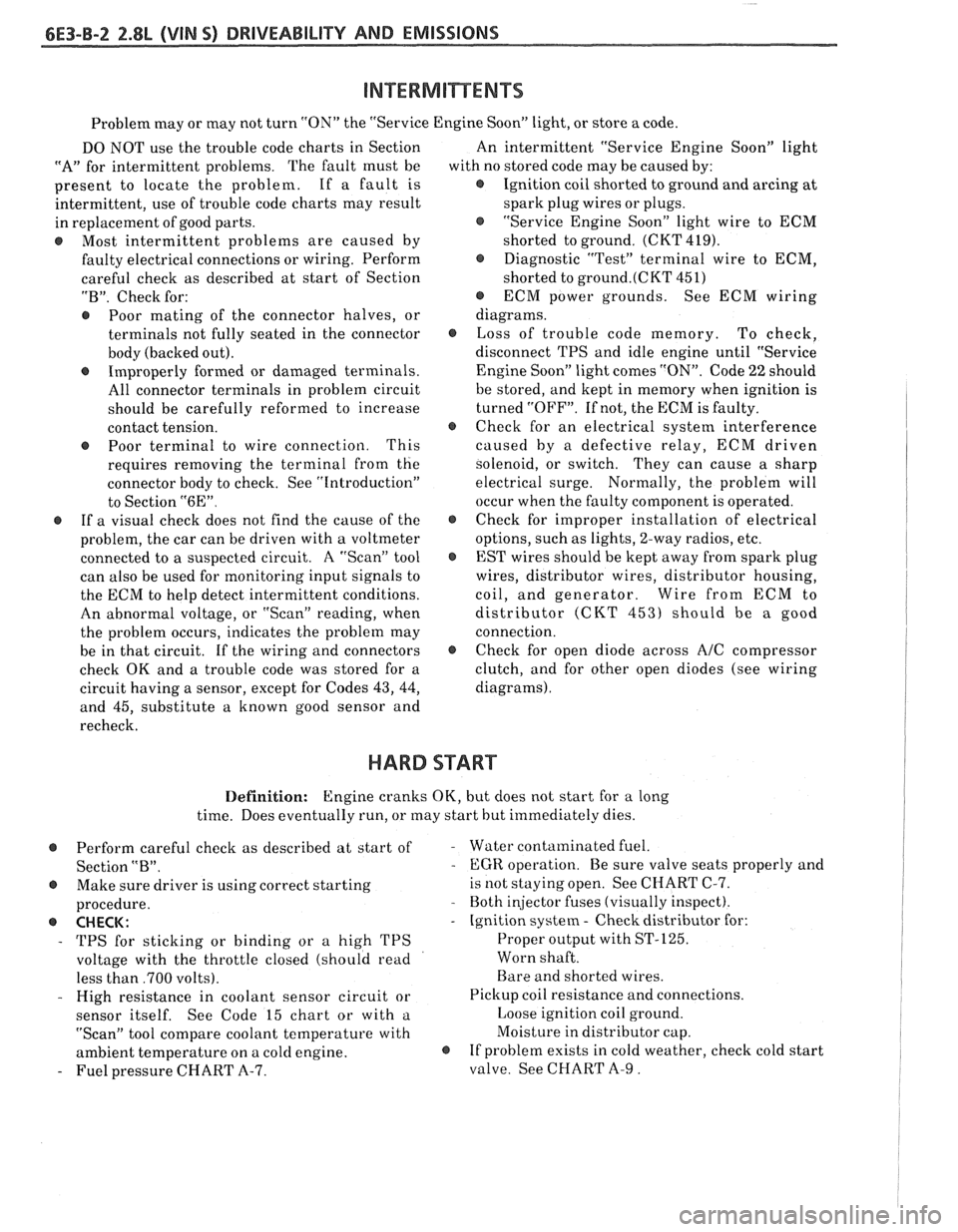
Problem may or may not turn "ON" the "Service Engine SoonJ' light, or store a code.
DO NOT use the trouble code charts in Section
"A" for intermittent problems. The fault must be
present to locate the problem. If a fault is
intermittent, use of trouble code charts may result
in replacement of good parts.
@ Most intermittent problems are caused by
faulty electrical connections or wiring. Perform
careful check as described at start of Section
"B". Check for:
@ Poor mating of the connector halves, or
terminals not fully seated in the connector
body (backed out).
@ Improperly formed or damaged terminals.
All connector terminals in problem circuit
should be carefully reformed to increase
contact tension.
@ Poor terminal to wire connection. This
requires removing the terminal from the
connector body to check. See "Introduction"
to Section
"6E".
@ If a visual check does not find the cause of the
problem, the car can be driven with a voltmeter
connected to a suspected circuit. A "Scan" tool
can also be used for monitoring input signals to
the ECM to help detect intermittent conditions.
An abnormal voltage, or "Scan" reading, when
the problem occurs, indicates the problem may
be in that circuit. If the wiring and connectors
check OK and a trouble code was stored for a
circuit having a sensor, except for Codes
43, 44,
and 45, substitute a known good sensor and
recheck. An
intermittent "Service Engine Soon" light
with no stored code may be caused by:
@ Ignition coil shorted to ground and arcing at
spark plug wires or plugs.
@ "Service Engine Soon" light wire to ECM
shorted to ground. (CKT 419).
@ Diagnostic "Test" terminal wire to ECM,
shorted to
ground.(CKT 451)
@ ECM power grounds. See ECM wiring
diagrams.
@ Loss of trouble code memory. To check,
disconnect TPS and idle engine until "Service
Engine Soon" light comes "ON". Code
22 should
be stored, and kept in memory when ignition is
turned "OFF". If not, the ECM is faulty.
@ Check for an electrical system interference
caused by a defective relay, ECM driven
solenoid, or switch. They can cause
a sharp
electrical surge. Normally, the problem will
occur when the faulty component is operated.
@ Check for improper installation of electrical
options, such as lights, 2-way radios, etc.
@ EST wires should be kept away from spark plug
wires, distributor wires, distributor housing,
coil, and generator. Wire from ECM to
distributor (CKT
453) should be a good
connection.
@ Check for open diode across A/C compressor
clutch, and for other open diodes (see wiring
diagrams).
HARD START
Definition: Engine cranks OK, but does not start for a long
time. Does eventually run, or may start hut immediately dies.
@ Perform careful check as described at start of -
Section "B".
@ Make sure driver is using correct starting
procedure.
@ CHECK:
- TPS for sticking or binding or a high TPS
voltage with the throttle closed (should read
less than
,700 volts).
- High resistance in coolant sensor circuit or
sensor itself. See Code 15 chart or with
a.
"Scan" tool compare coolant temperature with
ambient temperature on
a cold engine. 8
- Fuel pressure CHART A-7. Water contaminated
fuel.
EGR operation. Be sure valve seats properly and
is not staying open. See CHART C-7.
Both injector fuses (visually inspect).
Ignition system
- Check distributor for:
Proper output with ST-125.
Worn shaft.
Bare and shorted wires.
Pickup coil resistance and connections.
Loose ignition coil ground.
Moisture in distributor cap.
If problem exists in cold weather, check cold start
valve. See CHART A-9.
Page 867 of 1825
6E3-B-2 5.OL (VIN F) & 5.7L (VIN 8) DRIVEABILITY AND EMISSIONS
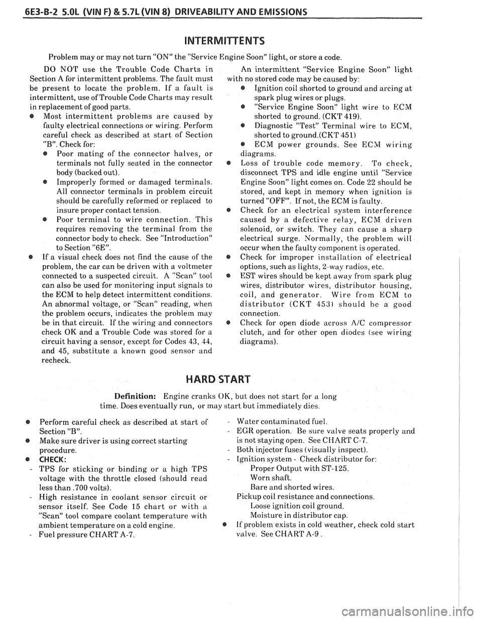
Problem may or may not turn "ON" the "Service Engine Soon" light, or store a code.
DO NOT use the Trouble Code Charts in
An intermittent "Service Engine Soon" light
Section A for intermittent problems. The fault must
with no stored code may be caused by:
be present to locate the problem. If a fault is
@ Ignition coil shorted to ground and arcing at
intermittent, use of Trouble Code Charts
may result
spark plug wires or plugs.
in replacement of good parts.
"Service Engine Soon" light wire to
ECM
@ Most intermittent problems are caused by
shorted to ground. (CKT 419).
faulty electrical connections or wiring. Perform
Diagnostic "Test" Terminal wire to ECM,
careful check as described at start of Section
shorted to
ground.(CKT 451)
"B". Check for:
@ ECM power grounds. See ECSI wiring
@ Poor mating of the connector halves, or diagrams.
terminals not fully seated in the connector
@ Loss of trouble code memory. To check,
body (backed out). disconnect TPS and idle engine until "Service
@ Improperly formed or damaged terminals.
Engine Soon" light comes on. Code 22 should be
All connector terminals in problem circuit
stored, and kept in memory when ignition is
should be carefully reformed or replaced to turned "OFF". If not, the ECM is faulty.
insure proper contact tension.
@ Check for an electrical system interference
@ Poor terminal to wire connection. This caused by a defective relay, ECM driven
requires removing the terminal from the
solenoid, or switch. They can cause a sharp
connector body to check. See "Introduction"
electrical surge. Normally, the problem will
to Section
"6E". occur when the faulty component is operated.
@ If a visual check does not find the cause of the @ Check for improper installation of electrical
problem, the car can be driven with a voltmeter
options, such as lights,
%way radios, etc.
connected to
a suspected circuit. A "Scan" tool
EST wires should be kept away from spark plug
can also be used for monitoring input signals to wires, distributor wires, distributor housing,
the ECM to help detect intermittent conditions. coil, and generator. Wire from
ECM to
An abnormal voltage, or "Scan" reading, when distributor
(CKT 453) should be a good
the problem occurs, indicates the problem
may connection.
be in that circuit. If the wiring and connectors
@ Check for open diode across AIC compressor
check OK and a Trouble Code was stored for a
clutch, and for other open diodes (see wiring
circuit having a sensor, except for Codes
43, 44, diagrams).
and 45, substitute a known good sensor and
recheck.
HARD START
Definition: Engine cranks OK, but does not start for a long
time. Does eventually run, or may start but immediately dies.
Perform careful check as described at start of
Section
"B".
@ Make sure driver is using correct starting
procedure.
@ CHECK:
- TPS for sticking or binding or a high TPS
voltage with the throttle closed (should read
less than
.700 volts).
- High resistance in coolant sensor circuit or
sensor itself. See Code 15 chart or with
a
"Scan" tool compare coolant temperature with
ambient temperature on a cold engine.
- Fuel pressure CHART A-7.
- Water contaminated fuel.
- EGR operation. Be sure valve seats properly and
is not staying open. See CHART C-7.
- Both injector fuses (visually inspect).
- Ignition system - Check distributor for:
Proper Output with ST-125.
Worn shaft.
Bare and shorted wires.
Pickup coil resistance and connections.
Loose ignition coil ground.
Moisture in distributor cap.
@ If problem exists in cold weather, check cold start
valve. See CHART A-9.
Page 1166 of 1825
CONTENTS
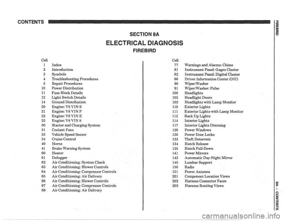
ELECTRICAL DIAGNOSIS
Cell
1
2
3
4 5
10
11
12 14
20
21
22
23
30
31
33
34
40
4
1
60
61
62
63
64
65
66
67
68
Index
Introduction
Symbols
Troubleshooting Procedures Repair Procedures
Power Distribution
Fuse Block Details
Light Switch Details
Ground Distribution
Engine:
V6 VIN S
Engine: V8 VIN
F
Engine: V8 VIN E
Engine:
V8 VIN 8
Starter and Charging System
Coolant Fans
Vehicle Speed Sensor
Cruise Control Horns
Brake Warning System
Heater
Defogger
Air Conditioning: System Check
Air Conditioning: Blower Controls
Air Conditioning: Compressor Controls
Air Conditioning: Air Delivery
Air Conditioning: Blower Controls
Air Conditioning: Compressor Controls
Air Conditioning: Air Delivery Cell
77
8
1
82
86 90
9
1
100
102
103
110
111
112
114
117
120
130
133
134
135
141
143
145
150
151
201 202
203
Warnings and Alarms: Chime
Instrument Panel: Gages Cluster
Instrument Panel:
Digital Cluster
Driver Information Center
(DIC)
WiperlWasher
WiperlWasher: Pulse
Headlights
Headlight Doors
Headlights with Lamp Monitor
Exterior Lights
Exterior Lights with Lamp Monitor
Back Up Lights
Interior Lights
Interior Lights Dimming
Power Windows
Power Door Locks
Theft Deterrent
Hatch Release
Hatch Pull-Down
Power Mirrors
Automatic Day-Night Mirror
Lumbar Support
Radio Power Antenna
Component Location Views
Harness Connector Faces
Harness Routing Views
Page 1167 of 1825
Page
Air Conditioning
Air Delivery
Electronic
.................... 68-0
Manual
....................... 65-0
Blower Controls
Electronic
.................... 66-0
Manual
....................... 63-0
Compressor Controls Electronic
.................... 67-0
Manual
....................... 64-0
................... System Check 62-0
Alarms (Audible)
Chime
......................... 77-0
Antenna(Power) ................... 151-0
Brakes
................. Warning System 41-0
................... Charging system 30-7
...................... Cigar Lighter 114-0
Circuit Breaker Details
PWR ACC Circuit
.......... Breaker 10.1.10.3.10.5.1 1.3
WDO Circuit Breaker
10.1. 10.3. 10.5. 11-4
.......... Component Location Views 201-0
Connectors (Harness Connector Faces) 202-0
el00 .......................... 202-0
............... Junction Block ((2238) 202-2
Coolant Fan
....................... 31-0
Cruise Control
..................... 34-0
Defogger
......................... 61-0
Digital Clock
...................... 150-0
Displays Digital Cluster
.................. 82-0
Coolant Temperature
........... 82-2
Page
......................... Fuel 82-3
................... Oil Pressure 82-2
.................. Speedometer 82-3
................. Door Locks (Power) 130-0
...... Driver Information Center (DIC) 86-0
Engines
... Multi-Port Fuel Injection (VIN S) 20-0
.... Multi-Port Fuel Injection (VIN 8) 23-0
.... Throttle
Body Injection (VIN E) 22-0
...... Tuned
Port Injection (VIN F) 21-0
................. Fuse Block Details 11-0
Fuse Details
........... INST LP 10.0.10.2.10.4.1 1.1
.............. TAIL 10.0.10.2.10.4.1 1.2
................ CRANK 10.0.10.2.1 0.4
.............. CTSY 10~0.10.2.10.4.1 1.2
......... STOP HAZ 10.1.10.3.10.5.1 1.3
............ RADIO 10.1.10.3.10.5.1 1.4
............ WIPER 10.1.10.3.10.5.1 1.4
.................... HATCH 10.2.1 0.4
........... HTR AlC 10.1.10.3.10.5.1 1.4
........... CIH.FAN 10.1.10.3.10.5.1 1.4
......... TURN BIU 10.1.10.3.10.5.1 1.4
............ GAGES 10.1.10.3.10.5.1 1.4
ECM-IGN
(V6 VIN S. V8 VIN F.
........ V8 VIN 8. V8 VIN E) 10.1.1 1.7
............ INJ 1 (V6 VIN S) 10.1.1 1.10
......... FPIINJ 2 (V6 VIN S) 10.1.1 1.10
... INJ 1 (V8 VIN F. V8 VIN 8) 10.3.1 1.11
FPIINJ 2 (V8 VIN F. V8 VIN 8) 10.3.1 1.11
............ CLSTR 10.1.10.3.10.5.1 1.13
............. FPIINJ 2 (V8 VIN E) 11-12
Page
Gages
................... Gages Cluster 81-0
........... Coolant Temperature 81-2
......................... Fuel 81-3
................... Oil Pressure 81-2
.................. Speedometer 81-3
................ Ground Distribution 14-0
Harness Routing Views
............. 203-0
........................... Heater 60-0
............................ Horns 40-0
Indicators
.................. Digital Cluster 82-0
................ Brake Warning 82-4
.................. Fasten Belts 82-1
...................... Hi Beam 82-1
...................... Security 82-1
............ Service Engine Soon 82-4
......................... Shift 82-5
......................... Turn 82-1
................... Gages Cluster 81-0
................ Brake Warning 81-0
.................. Fasten Belts 81-0
...................... Hi Beam 81-0
............ Service Engine Soon 81-0
......................... Shift 81-1
......................... Turn 81-0
Instrument Panel
Digital Cluster
.................. 82-0
Gages Cluster
................... 81-0
............ Interior Lights Dimming 117-0
...................... Introduction 2-0
Lights (Exterior)
........................ Back Up 112-0
...................... Fog 100.3,10 3.0
Page 1168 of 1825
INDEX
Page
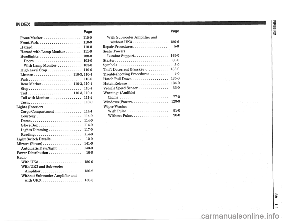
................... Front Marker 110-0
...................... Frontpark 110-0
......................... Hazard 110-0
........ Hazard with Lamp Monitor 111-0
..................... Headlights 100-0
........................ Doors 102-0
............ With Lamp Monitor 103-0
................. Nigh Level Stop 110-0
................... License 110.3,11 0.4
Park
........................... 110-0
............... Rear Marker 110.3,11 0.4
stop
........................... 110-1
...................... Tail 110.3,11 0.4
................ Tail with Monitor 111-2
Turn ........................... 110-0
Lights (Interior)
.............. Cargo Compartment 114-1
....................... Courtesy 114-0
.......................... Dome 114-0
...................... Glove Box 114-0
................. Lights Dimming 117-0
........................ Reading 114-0
................ Light Switch Details 12-0
.................... Mirrors (Power) 141-0
Automatic
DayINight ............ 143-0
................. Power Distribution 10-0
Radio
...................... With UK3 150-0
With
UK3 and Subwoofer
..................... Amplifier 15 0-2
Without Subwoofer Amplifier and
with
UK3 ..................... 150-5 With
Subwoofer Amplifier and
without UK3
..................
.................. Repair Procedures
Seats (Power)
Lumbar Support
.................
Starter ............................
........................... Symbols
........... Theft Deterlent (Passkey)
......... Troubleshooting Procedures
.................. Hatch Pull-Down
..................... Hatch Release
............... Vehicle Speed Sensor
Warnings (Audible)
Chime
.........................
................... Windows (Power)
WiperIWasher
With Pulse .....................
................... Without Pulse
Page
Page 1172 of 1825
INTRODUCTION
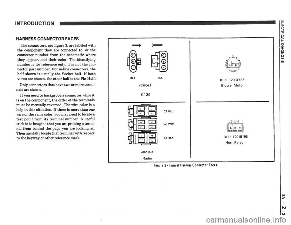
HARNESS CONNECTOR FACES
The connectors, see figure 3, are labeled with
the component they are connected to, or the
connector number from the schematic where
they appear, and their color. The identifying
number is for reference only; it is not the con-
nector part number. For in-line connectors, the
half shown is usually the Socket half. If both
views are shown, the other half is the Pin
Half.
Only connectors that have two or more termi-
nals are shown.
If you need to backprobe a connector while it
is on the component, the order of the terminals
must be mentally reversed. The wire color is a
help
in this situation. If there is more than one
wire of the same color, you may need to locate a
test point from its terminal number.
A useful
trick is to imagine that you are probing a termi-
nal from behind the page you are looking at.
Then mentally locate that terminal with respect
to the keyway or other reference mark.
v03000.2 Blower Motor
C3 BLU
C2 WHT
C1 BLK
v00010.0
Radio
BLU 12015196
Horn Relav
Figure 3 -Typical Harness Connector Faces
Page 1186 of 1825
TROUBLESHOOTING TESTS m r rn 0
With a Short Finder
1. Remove the blown fuse, leaving the Battery
connected.
2. Connect the Short Finder across the fuse
terminals.
3. Close all switches in series with the circuit
you are troubleshooting.
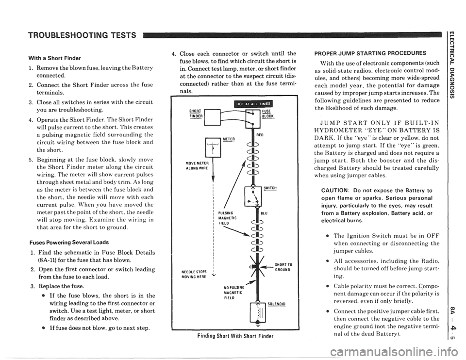
4. Operate the Short Finder. The Short Finder
will pulse current to the short. This creates
a pulsing magnetic field surrounding the
circuit wiring between the fuse block and
the short.
5. Beginning at the fuse block. slowly move
the Short Finder meter along the circuit
wiring. The meter will show current pulses
through sheet
inetal and body trim. As long
as the meter is between the fuse block and
the short, the needle will move with each
current pulse. When you have
moved the
meter past the point of the short. the needle
will stop
moving. Examine the wiring in
that area for the short to ground.
Fuses Powering Several Loads
1. Find the schematic in Fuse Block Details
(8A-11) for the fuse that has blown.
2. Open the first connector or switch leading
from the fuse to each load.
3. Replace the fuse.
@ If the fuse blows, the short is in the
wiring leading to the first connector or
switch. Use a test light, meter, or short
finder as described above.
@ If fuse does not blow, go to next step.
4. Close each connector or switch until the PROPER JUMP STARTING PROCEDURES
fuse blows, to find which circuit the short is
With the use of electronic components (such
in. Connect test lamp, meter, or short finder
as solid-state radios, electronic control
mod- at the connector to the suspect circuit (dis- ules, and others) becoming more wide-spread
connected) rather than at the fuse termi- each model year, the potential for damage nals. caused by improper jump starts increases. The
SHORT FUSE FINDER - BLOCK -
MOVE METER
NEEDLE STOPS
MOVING HERE
NO PULSING
MAGNETIC
FIELD
Cb
SHORT TO
GROUND
w-
Finding Short With Short Finder
following guidelines are presented to reduce
the likelihood of such damage.
JUMP START ONLY IF BUILT-IN
HYDROMETER "EYE" ON BATTERY IS
DARK. If the "eye" is clear or yellow, do not
attempt to jump start. If the "eye" is green,
the Battery is charged and does not require a
jump start. Both the booster and the dis-
charged Battery should be treated carefully
when using jumper cables.
CAUTION: Do not expose the Battery to
open flame or sparks. Serious personal
injury, particularly
to the eyes, may result
from
a Battery explosion, Battery acid, or
electrical burns.
The Ignition Switch must be in OFF
when connecting or disconnecting the
jumper cables.
All accessories. including the Radio.
should be turned off before jump start-
ing.
Cable polarity must be correct. Compo-
nent damage can occur
if the polarity is
re~~ersed. even if only briefly.
a Connect the positive jumper cable first.
then connect the negative cable to the
engine ground (not the negative termi-
nal of the dead Battery).
Page 1217 of 1825
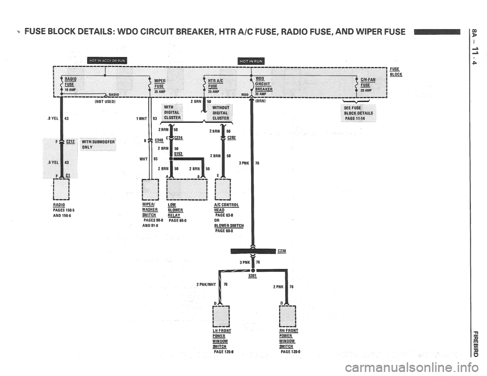
FUSE BLOCK DETAILS: WDO ClRGUlT BREAKER, HTR A16 FUSE, RADlO FUSE, AND WIPER FUSE
RADIO - PAGES 150-5 AND 150.6
WIPER1 LOW A/C CONTROL
WASHER BLOWER HEAD - SWlTCH PAGE 63-0 PAGES 90-0 PAGE 664 OR
AND 91-0 BLOWER SWITCH
PAGE 600
3 PNK 76
LH FRONT RH FRONT
POWER
- POWER WINDOW WINDOW
PAGE
120-0 PAGE 120-0