1988 PONTIAC FIERO service indicator
[x] Cancel search: service indicatorPage 267 of 1825
4B1-14 REAR AXLE
8. Shims should be clean and free from burrs.
9. Check rear cover for tears and any damage which
may prevent effective sealing.
10. Discard all damaged bolts.
Assemble
Differential Assembly
Lubricate all gears and thrust washers with rear
axle lubricant.
Install side gears thrust washers in differential
case. Hold washers in place with grease.
Install side gear in differential case large half.
Position thrust block in case.
Drive long pinion cross shaft through case,
thrust washers, pinion, and thrust block bores.
Align retainer pin hole with hole in
case.Caution
should be taken so differential pinion thrust
washers are not damaged.
Install other two pinions and thrust washers in
differential case large half. Drive two short pinion
cross shafts through case, pinions and into thrust
block bores. Align retainer pin holes with holes
in case.
Drive three cross shaft retaining pins through
case and shafts. Leave the long cross shaft
retaining pin protruding 6 mm from case locating
other case half.
Install remaining side gear and thrust washer in
small case half.
Install side gear through case bore, and mate the
case halves on retaining pin. Rotate side gear to
ensure that gears are meshing.
Install ring gear on housing and tighten bolts to
the specified torque.
Flanged head durlok bolts can be re-used after
cleaning.
Important
NOTICE: Left hand thread bolts.
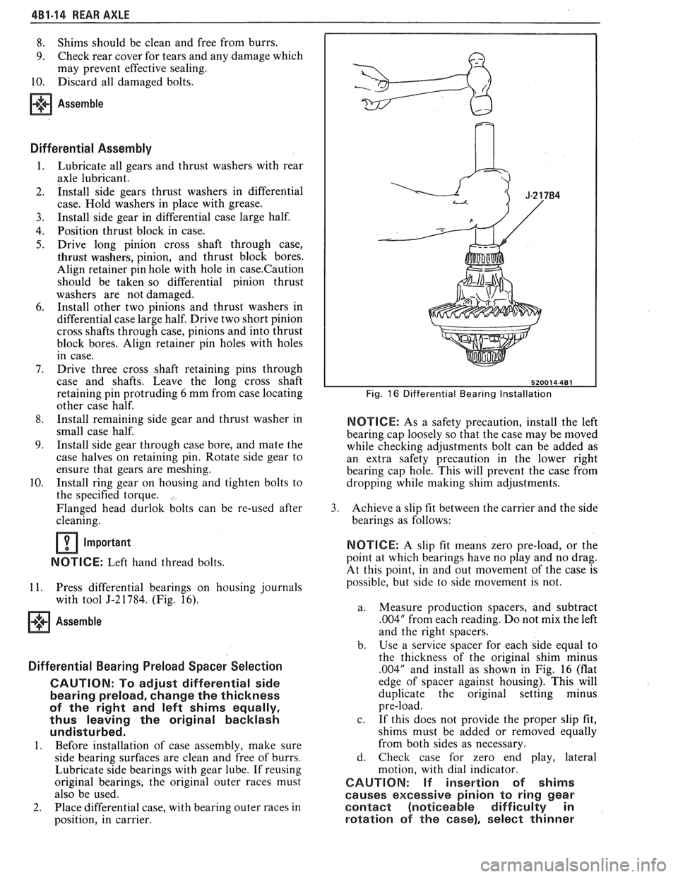
11. Press differential bearings on housing journals
with tool
5-2 1784. (Fig. 16).
Assemble
Differential Bearing Preload Spacer Selection
CAUTION: Po adjust differential side
bearing preload, change the thickness
of the right and left shims equally,
thus leaving the original backlash
undisturbed.
1. Before installation of case assembly, make sure
side bearing surfaces are clean and free of burrs.
Lubricate side bearings with gear lube. If reusing
original bearings, the original outer races must
also be used.
2. Place differential case, with bearing outer races in
position, in carrier.
Fig. 16 Differential Bearing Installation
NOTICE: As a safety precaution, install the left
bearing cap loosely so that the case may be moved
while checking adjustments bolt can be added as
an extra safety precaution in the lower right
bearing cap hole. This will prevent the case from
dropping
while making shim adjustments.
3. Achieve a slip fit between the carrier and the side
bearings as follows:
NOTICE: A slip fit means zero pre-load, or the
point at which bearings have no play and no drag.
At this point, in and out movement of the case is
possible, but side to side movement is not.
a. Measure production spacers, and subtract
.004" from each reading. Do not mix the left
and the right spacers.
b. Use
a service spacer for each side equal to
the thickness of the original shim minus
.004" and install as shown in Fig. 16 (flat
edge of spacer against housing). This will
duplicate the original setting minus
pre-load.
c. If this does not provide the proper slip fit,
shims must be added or removed equally
from both sides as necessary.
d. Check case for zero end play, lateral
motion, with dial indicator.
CAUTION: If insertion of shims
causes excessive pinion to ring gear
contact (noticeable difficulty in
rotation of the case), select thinner
Page 269 of 1825
4B1-16 REAR AXLE
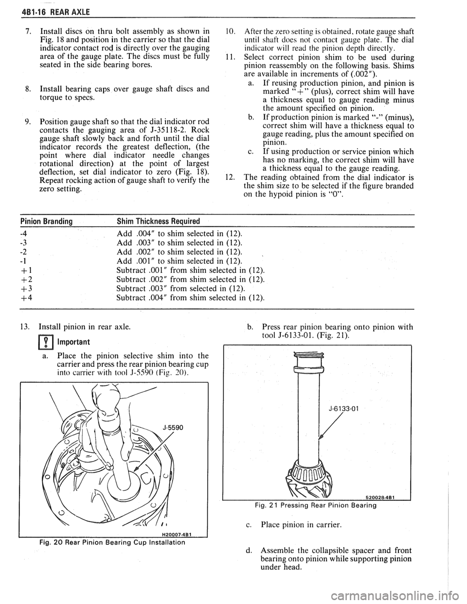
7. Install discs on thru bolt assembly as shown in 10. After the zero setting is obtained, rotate gauge shaft
Fig.
18 and position in the carrier so that the dial
until shaft does not contact gauge plate. The dial
indicator contact rod is directly over the gauging
indicator will read the pinion depth directly.
area of the gauge plate. The discs must be fully
11.
Select correct pinion shim to be used during
seated in the side bearing bores.
pinion reassembly on the following basis. Shims
are available in increments of
(.002").
a.
If reusing production pinion, and pinion is 8. Install bearing caps over gauge shaft discs and
marked "+" (plus), correct shim will have
torque to specs.
a thickness equal to gauge reading minus
the amount specified on
ini ion.
Position gauge shaft so that the dial indicator rod
contacts the gauging area of J-35 1 18-2. Rock
gauge shaft slowly back and forth until the dial
indicator records the greatest deflection, (the
point where dial indicator needle changes
rotational direction) at the point of largest
deflection, set dial indicator to zero (Fig. 18).
Repeat rocking action of gauge shaft to verify the
zero setting. b. If production-pinion is marked "-" (minus),
correct shim will have a thickness equal to
gauge reading, plus the amount specified on
pinion.
c. If using production or service pinion which
has no marking, the correct shim will have
a thickness equal to the gauge reading.
The reading obtained from the dial indicator is
the shim size to be selected if the figure branded
on the
hypoid pinion is "0".
Pinion Branding Shim Thickness Required
-4
Add ,004" to shim selected in (12).
- 3 Add ,003" to shim selected in (12).
-2 Add .002" to shim selected in (12).
- 1 Add ,001" to shim selected in (12).
+ 1 Subtract .001" from shim selected in (12).
+2 Subtract .002" from shim selected in (12).
+3 Subtract ,003" from selected in (12).
+4 Subtract ,004" from shim selected in (12).
13. Install pinion in rear axle.
Important
a. Place the pinion selective shim into the
carrier and press the rear pinion bearing cup
into carrier with
tool 3-5590 (Fig. 30).
b. Press rear pinion bearing onto pinion with
tool
5-6133-01. (Fig. 21).
Fig. 21 Pressing Rear Pinion Bearing
c. Place pinion in carrier.
Fig. 20 Rear Pinion Bearing Cup Installation
d. Assemble the collapsible spacer and front
bearing onto pinion while supporting pinion
under head.
Page 287 of 1825
4B-14 REAR AXLE
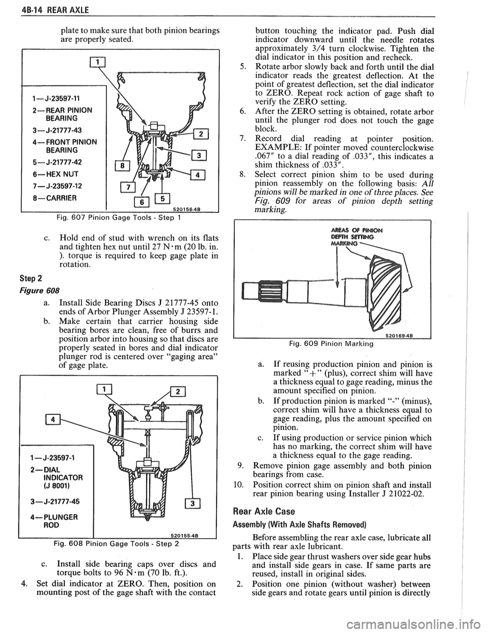
plate to make sure that both pinion bearings
are properly seated.
1 - J-23597-11
2-- REAR PINION
3--- J-21777-43
4---- FRONT PINION
5- J-21777-42
6-HEX NUT
7 - J-23597-12
Fig. 607 Pinion Gage Tools - Step 1
c. Hold end of stud with wrench on its flats
and tighten hex nut until 27
N.m (20 lb. in.
). torque is required to keep gage plate in
rotation.
Step 2
Figure 608
a. Install Side Bearing Discs J 21777-45 onto
ends of Arbor Plunger Assembly
J 23597- 1.
b. Make certain that carrier housing side
bearing bores are clean, free of burrs and
position arbor into housing so that discs are
properly seated in bores and dial indicator
plunger rod is centered over "gaging area"
of gage plate.
1 - J-23597-4
3- J-21777-45
4--- PLUNGER
Fig. 608 Pinion Gage Tools
- Step 2
c.
Install side bearing caps over discs and
torque bolts to 96
N-m (70 lb. ft.).
4. Set dial indicator at ZERO. Then, position on
mounting post of the gage shaft with the contact button
touching the indicator pad. Push dial
indicator downward until the needle rotates
approximately 3/4 turn clockwise. Tighten the
dial indicator in this position and recheck.
5. Rotate arbor slowly back and forth until the dial
indicator reads the greatest deflection. At the
point of greatest deflection, set the dial indicator
to ZERO. Repeat rock action of gage shaft to
verify the ZERO setting.
6. After the ZERO setting is obtained, rotate arbor
until the plunger rod does not touch the gage
block.
7. Record dial reading at pointer position.
EXAMPLE: If pointer moved counterclockwise
.067" to a dial reading of .033", this indicates a
shim thickness of
,033 " .
8. Select correct pinion shim to be used during
pinion reassembly on the following basis:
All
pinions will be marked in one of three places. See
Fig. 609 for areas of pinion depth setting
marking.
Fig. 609 Pinion Marlcing
a.
If reusing production pinion and pinion is
marked
"+" (plus), correct shim will have
a thickness equal to gage reading, minus the
amount specified on pinion.
b. If production pinion is marked
"-" (minus),
correct shim will have
a thickness equal to
gage reading, plus the amount specified on
pinion.
c. If using production or service pinion which
has no marking, the correct shim will have
a thickness equal to the gage reading.
9. Remove pinion gage assembly and both pinion
bearings from case.
10. Position correct shim on pinion shaft and install
rear pinion bearing using Installer
J 21022-02.
Rear Axle Case
Assembly (With Axle Shafts Removed)
Before assembling the rear axle case, lubricate all
parts with rear axle lubricant.
1. Place side gear thrust washers over side gear hubs
and install side gears in case. If same parts are
reused, install in original sides.
2. Position one pinion (without washer) between
side gears and rotate gears until pinion is directly
Page 364 of 1825
2.8 LITER V.6 6A2.13
Torque bolts as shown in Figure 6A2-15.
4. Install
push rods and loosely retain with rocker
arms. Make sure lower ends of
pushrods are in
lifter seats.
5. Install intake manifold.
6. Raise vehicle.
7. Install dipstick tube bracket.
8. Connect exhaust pipe
to exhaust manifold flange.
9. Lower vehicle.
10. Adjust
valve lash as previously outlined.
11. Continue
following intake manifold installation
for build up.
Removal (Right)
Remove intake manifold as previously outlined.
Raise vehicle.
Disconnect exhaust pipe.
Drain engine block.
Lower vehicle.
Loosen rocker arms until able to remove push
rod.
Remove serpentine belt.
Remove tensioner.
Remove A.I.R. bracket.
Remove generator bracket.
Remove head bolts.
Remove head.
Installation (Right)
The gasket surfaces on both the head and cylinder
case
deck must be clean of any foreign matter and free
of nicks of heavy scratches. Cylinder bolt threads in the
case and threads on the cylinder head bolts must be
clean. Dirt will affect bolt torque.
1. Place the gasket in position, over the dowel pins,
with the note "This Side Up" showing.
2. Install cylinder head.
3. Coat cylinder head bolt threads with sealer,
#lo52080 or equivalent, and install bolts.
Torque bolts as shown in (Figure
6A2-15).
Install push rods and loosely retain with rocker
arms. Make sure lower ends of push rods are in
lifter seats.
Install intake manifold.
Raise vehicle.
Install exhaust pipe to exhaust manifold flange.
Lower vehicle.
Adjust valve lash as previously outlined.
Install AIR bracket.
Install tensioner.
Install generator bracket.
Continue following intake manifold installation
for build up.
Disassembly
1. With cylinder head removed, remove rocker arm
nuts, balls and rocker arms (if not previously
done).
2. Using tool J-8062, compress the valve springs and
remove valve keys. Release the compressor tool and
remove spring caps, oil shedders, springs and
damper assemblies, then remove oil seals.
3. Remove valves from cylinder head and place
them in a rack so they can be installed in their
original positions.
Cleaning and Inspection
Clean all carbon from combustion chambers and
valve ports using 'tool
5-8089.
Thoroughly clean valve guides using 5-8 10 1.
Clean all carbon and sludge from push rods,
rocker arms and push rod guides.
Clean valve stems and heads on a buffing wheel.
Clean carbon deposits from head gasket mating
surface.
Inspect cylinder head for cracks in the exhaust
ports, combustion chambers, or external cracks
to the water jacket.
Inspect the valves for burned heads, cracked faces
or damaged stems.
NOTICE: Excessive valve stem to bore clearance
will cause high oil consumption and may cause
valve breakage. Insufficient clearance will result in
noise and sticky functioning of the valve and
disturb engine smoothness.
8. Measure valve stem clearance as follows:
a. Clamp
a dial indicator on one side of the
cylinder head. Locate the indicator so that
movement of the valve stem from side to
side (crosswise to the head) will cause direct
movement of the indicator stem. The
indicator stem must contact the side of the
valve stem just above the guide.
b. Drop
the valve head
1.5mm off the valve
seat.
c. Move
the stem of the valve from side to side,
using light pressure, to obtain a clearance
reading. If clearance exceeds specifications,
it will be necessary to ream valve guides for
oversize valves. Service valves are available
in std., 089,
.394 and .775mm O.S. sizes.
9. Check
valve spring tension with tool J-8056,
spring tester. Springs should be compressed to the
specified height and checked against the
specifications chart. Springs should be replaced if
not within 44
N (10 Ibs.) of the specified load
(without dampers).
10. Inspect
rocker arm studs for wear or damage.
ROCKER ARM STUDS
Cylinder heads use threaded rocker arm studs.
Rocker arm studs that have damaged threads should
be replaced with new studs. If, for some reason, the
threads in the head
are damaged or stripped, the head
can be retapped, and a helical type insert added. If such
an insert is not available, the head should be replaced.
VALVE GUIDES
Valves with oversize stems are available in .089,
,394 and ,775mm over sizes. To ream the valve guide
Page 464 of 1825
CHARGING SYSTEM 6D3-1
SECTION 6D3
CHARG NG SYSTEM
CONTENTS
General Description ................................. 6D3- 1 Charging System ........................................ 6D3- 1
.......................................... Charging System - CS ............................... 6D3- 1 On-Car Service 6D3-2
................................................... Diagnosis .. 6D3- 1 Generator 6D3-3 ...................... ......................... ............................................. 6D3- 1 Specifications 6D3-3 Service Procedures .................................. Unit Repair .. 6D3-4-6 ............................... ............
GENERAL DESCRIPTION
The engine electrical system includes the battery,
ignition (primary and secondary), starter (and related
wiring) and the generator (and related wiring).
Diagnostic charts (see Section 6D) will aid in
trouble-shooting system faults. When a fault is traced
to a particular component, refer to that components'
section of the service manual.
CHARGING SYSTEM-CS
The CS Charging System has several sizes
available, including the CS-130 and CS-144. The
number (130 or 144) denotes the
OD in mm of the
stator laminations.
CS generators use a new type regulator and a
diode trio is not used. A delta stator, rectifier bridge,
and rotor with slip rings and brushes are electrically
similar to earlier generators. A conventional pulley and
fan is used and, on the CS-130, an internal fan cools the
slip ring end frame, rectifier bridge and regulator.
Unlike three-wire generators, the CS-130 and
CS-144 may be used with only two connections
-
battery positive and an "L" terminal to the charge
indicator bulb. Use of "P",
"F", and "S" terminals is
optional. The "P" terminal is connected to the stator,
and may be connected externally to
a tachometer or other
device. The
"F" terminal is connected internally
to field positive, and may be used as a fault indicator.
The "S" terminal may be connected externally to a
voltage, such as battery voltage, to sense voltage to be
controlled.
As on other charging systems, the charge
indicator lights when the switch is closed, and goes out
when the engine is running. If the charge indicator is
on with the engine running, a charging system defect
is indicated. For all kinds of defects, the indicator will
glow at full brilliance, not "half lit". Also, the charge
indicator will be on with the engine running if system
voltage is too high or too low. The regulator voltage
setting varies with temperature, and limits system
voltage by controlling rotor field current.
This regulator switches rotor field current on and
off at a fixed frequency of about 400 cycles per second.
By varying the on-off time, correct average field
current for proper system voltage control is obtained.
At high speeds, the on-time may be 10% and the
off-time 90%. At low speeds, with high electrical loads,
on-off time may be 90% and
lo%, respectively.
No periodic maintenance on the generator is
required.
DIAGNOSIS
SERVICE PROCEDURES
CHARGING SYSTEM
The generator does not require periodic
lubrication. The rotor shaft is mounted on ball bearings
at the drive end and roller bearings at the slip ring end.
Each contains a permanent grease supply. At periodic
intervals, check mounting bolts for tightness and adjust
belt tension (see Section
6B), if applicable.
e When adjusting belt tension, apply pressure at
center of generator, never against either end
frame.
GENERATOR BENCH CHECK-CS
To check generator in a test stand, remove as
specified in On-Car Service and proceed as follows: 1.
Make connections as shown in Figure
lH, except
leave the carbon pile disconnected. The ground
polarity of generator and battery must be the
same. The battery must be fully charged. Use a
30-500
OHM resistor between battery and "L"
terminal.
2. Slowly increase generator speed and observe
voltage.
3. If the voltage is uncontrolled and increases above
16.0 volts, the rotor field is shorted, the regulator
is defective, or both.
A shorted rotor field coil can
cause the regulator to become defective. NOTE:
The battery must be fully charged when making
this test.
Page 580 of 1825

DRIVEABILITY AND EMISSIONS - 5.OL (\/IN El 6EZ-CZ-5
sent to the ECM. The ECM then increases the injector
base pulse width, permitting increased fuel flow.
As the throttle valve rotates in response to
movement of the accelerator pedal, the throttle shaft
transfers this rotational movement to the
'I'PS. A
potentiometer (variable resistor) within the TPS
assembly changes its resistance (and voltage drop) in
proportion to throttle movement.
By applying a reference voltage (5.0 volts) to the
TPS input, a varying voltage (reflecting throttle
position) is available at the TPS output. For example,
approximately 2.5 volts results from a 50% throttle
valve opening (depending on TPS calibration). The
voltage output from the TPS assembly is routed to the
ECM for use in determining throttle position.
FUEL PUMP
The fuel pump is a turbine type, low pressure
electric pump, mounted in the fuel tank. Fuel
is
pumped at a positive pressure (above 62
kPa or 9 psi)
from the fuel pump through the in-line filter to the
pressure regulator in the TBI assembly Excess
fuel is
returned to the fuel tank through the fuel return line.
The fuel pump is attached to the fuel gage sender
assembly. A fuel strainer is attached to the fuel pump
inlet line and prevents dirt particles from entering the
fuel line and tends to separate
water from the fuel
Vapor lock problems are reduced when using an
electric
pump because the fuel is pushed from the tank
under pressure rather than being pulled
under
vacuum, a condition that produces vapor.
An inoperative fuel pump would cause
a. no start
condition. A fuel pump which does not provide enough
pressure can result in poor performance. (See "Fuel
System Pressure Test" procedure).
FUEL PUMP ELECTRICAL CIRCUIT
When the key is first turned "ON" without the
engine running, the ECM turns the
Fuel pump relay
"ON" for two seconds. This builds
up the fuel pressure
quickly. If the engine is not started within two
seconds, the
ECM shuts the fuel pump "OFF" and
waits until the engine starts. As soon as the engine is
cranked, the ECM turns the relay
"ON" and runs the
fuel pump.
As a backup system to the fuel pump relay, the
fuel pump can also be turned on
by the oil pressure
switch. The oil pressure sender has two circuits
internally. One operates the oil pressure indicator or
gage in the instrument cluster,
itnd the other is
anormally open switch which closes when oil pressure
reaches about 28
kPa (4 psi). If the fuel pump relay
fails, the oil pressure switch will run the fuel pump. An
inoperative fuel pump relay can result in long
cranking times, particularly if the engine is cold. The
oil pressure switch will turn on the fuel pump as soon
as oil pressure
reaches about 28 kPa (4 psi).
FUEL CONTROL
Always start with the "Diagnostic Circuit Check"
in Section
"6E2-A". This will reduce diagnosis time
and prevents unnecessary replacement of parts. The
information in this check will direct diagnosis
concerning "Engine
Crunlis But Won't Run" and the
"Fuel Control System," Section
"6E2-C2", including
diagnosis of an injector, pressure regulator,
fuel pump,
fuel
pump relay, and oil pressure switch.
Idle Air Control (IAC) Valve
A "Scan" tool reads IAC position in steps, calletl
"Counts." "0" steps indicates the ECM is commanding
the
IAC to be driven in, to a fully seiltetl position
(minimum idle air).
The higher the number steps, the
more idle air being allowed to pass
by the IAC valve.
cnose Refer to CHART C-2C for information to cliil,
the function of the IAC valve.
Driva bility
Refer to Section "B" for driveability symptoms
related to the fuel control.
ON-VEHICLE SERVICE
GENERAL SEWVICE INFORMATION
CAUTION:
e To prevent personal injury or damage to the
vehicle
as the result sf an accidental start,
disconnect and reconnect the negative
battery cable before and after service is
performed.
@ Also, catch any fuel that leaks out when
disconnecting the fuel lines, by covering the
fittings with
a shop cloth. Place the cloth in
an approved container when work is
complete.
The 'FBI unit repair procedures cover component
replacement with the unit on the vehicle,
tIowever,
throttle body replacement requires that the complete
unit
be removed from the enginc.
Page 968 of 1825
DRIVEABILITY AND EMISSIONS - FUEL INJECTION 6E-7
On engines that can be monitored in the open
mode, it allows certain parameters to be obtained
without changing the engine operating
characteristics. The parameters capable of being read
vary from engine family to engine family. Most
"Scan" tools are programmed so that the system will
go directly into the special mode
if the "open" mode is
not available.
ALDL (7 OK, or Special) Mode
(not used on
all engines)
In this mode, all information incorporated into a
specific
engine and ECM is obtainable. However, in
this mode the system operating characteristics are
modified as follows.
@ "Closed Loop" timers are bypassed
EST (spark) is advanced
@ IAC will control engine idle to 1000 rpm I
50 rpm (if applicable)
@ On some engines, canister purge solenoid will
be enabled
@ P/N restrict functions will be disabled.
Factory Test (Back-up or 3.9 K) Mode
(TBI, Port)
In this mode, the ECM is operating on the fuel
back-up logic and is calibrated by the Calpak or Mem-
cal. These are used to control the fuel delivery
if the
ECM fails. This mode verifies that the back-up feature
is OK. The parameters that can be read on a
"Scan"
tool in this mode are not of much use for service.
"SCAN" TOOL LIMITATIONS AND USE
The "Scan" tool allows a quick check of sensors
and switches which are inputs to the ECM. However,
on some applications the data update rate makes the
tool less effective as a voltmeter when trying to detect
an intermittent which lasts for a very short time.
However, the "Scan" tool allows one to manipulate
wiring harnesses or components under the hood while
observing the "Scan" readout. This helps in locating
intermittents with the engine not running.
intermittent Conditions
for a period of time to see if there is any change in the
readings that indicates intermittent operation.
The "Scan" tool is also a useful and quick way of
comparing operating parameters of a poorly operating
engine with a known good one. For example;
A sensor
may shift in value but not set a code. Comparing with
a known good vehicle may uncover the problem.
The "Scan" tool has the ability to save time in
diagnosis and prevent the replacement of good parts.
The key to using the "Scan" tool successfully for
diagnosis lies in the technician's ability to understand
the system he is trying to diagnose as well as an
understanding of the "Scan" tool's limitations.
Therefore, the technician should read the tool
manufacturer's operating manual to become familiar
with the operation. The following information will
describe most of the "Scan" tool positions and how
they can be helpful in diagnosis.
"SCAN" TOOL POSITIONS
The following positions may not be applicable to
all engines. See the facing page
of the diagnostic
circuit check for a particular engine to decide which
positions apply to that engine.
Mode
Check with the manufacturer to determine what
the function of this mode is. In most cases it allows the
user to place the ECM in different operating modes.
Injector Pulse Width
In this position, the reading is given in
milliseconds, which is the
"ON" time that the ECM is
commanding to the
injector(s1.
Closed LoopIOpen Loop
This position will indicate whether the engine
control system is operating in "Open Loop" or "Closed
Loop". Most systems go "Closed Loop" after a certain
amount of running time, when coolant temperature is
high enough, and the oxygen sensor becomes active.
Exhaust (RichILean Indicator)
The "Scan" tool is helpful in cases of intermittent
This indicates the O2 sensor voltage at the instant operation' The can be in and observed that the data stream is sampled. If voltage is less than
while driving the vehicle under the condition where
350 mv, the value will be lean. If above 550 mv, a rich the light comes "ON" momentarily, or the engine exhaust is indicated. driveability is poor momentarily. If the problem
seems to be related to certain areas that can be
Codes checked on the "Scan" tool, then those are the
positions that should be checked while driving the
This will display any trouble codes stored in the
vehicle. If there does not seem to be any correlation
ECM memory. between the problem and any specific circuit, the
"Scan" tool can be checked on each position, watching
Page 1122 of 1825
AUTOMATIC TMNSMISSION ON-VEHICLE SERVICE 7A1-3
e Propeller shaft oil seal worn or damaged
o Governor cover
e Line pressure pipe plug loose
@ Porous casting
3. Leak at converter end:
Converter seal damaged
- Seal lip cut. (Check converter hub for
damage.)
- Bushing moved forward and damaged
- Garter spring missing from seal
o Converter leak in weld area. (Refer to
Torque Converter.)
Porous casting (Case or pump)
4. Fluid comes out vent pipe or fill tube:
Over-filled
Water or coolant in fluid. Fluid will appear
milky.
e Case porous
e Incorrect fluid level indicator
e Plugged vent
e Drain back holes plugged
Mispositioned oil pump to case gasket (if
equipped)
Case Porosity Repair
1. Clean the leak area with solvent and air dry.
CAUTION: Epoxy adhesive may cause
skin irritations and eye damage. Read
and follow all information on the
container label as provided by the
manufacturer.
2. Mix a sufficient amount of epoxy adhesive,
# 1052533, or equivalent, following the
manufacturer's recommendations.
3. While the transmission case is hot, apply epoxy
adhesive with a clean, dry soldering acid brush.
4. Allow the epoxy adhesive to cure for three hours
before starting the engine.
5. Repeat fluid leak diagnosis procedures.
TORQUE CONVERTER CLUTCH ELECTRICAL
CONTROLS
The Torque Converter Clutch (TCC) system uses
controls that are internal as well as external to the
transmission. For internal control components of the
TCC system, refer to the I-Iydraulic Diagnosis Section
for for wiring diagrams and switch locations.
The external control components of the TCC
system include:
1. Brake Release Switch - To avoid stalling the
engine when braking, the converter clutch is
released any time the brakes are applied.
2. Electronic Control ModuOe - Receives input
signals and grounds TCC solenoid to apply clutch
when proper operating conditions are met.
3. Throttle Position Sensor - Sends throttle
position information to Electronic Control
Module.
4. Vacuum Sensor - Sends engine vacuum (load)
information to Electronic Control Module.
5. Vehicie Speed Sensor - Sends vehicle speed
information to Electronic Control Module.
6. Coolant Temperature Sensor - Sends engine
coolant temperature information to Electronic
Control Module.
TORQUE CONVERTER CLUTCH DIAGNOSIS
To properly diagnose the Torque Converter
Clutch (TCC) system perform all electrical testing first
and then the hydraulic testing. Refer to the appropriate
Driveability and Emissions Section (6E) for additional
Torque Converter Clutch Information
ON-VEHICLE SERVICE
SI-IIFT CONTROL CABLE
Remove or Disconnect (Fig. 1)
1. Negative battery cable.
2. Raise car, see Section OA.
3. Cable attachments at transmission.
4. Lower car.
5. Console, see Section
8C.
6. Cable at control lever and base.
7. Cable from floor.
install or Connect
1. Cable to floor.
2. Cable at base and control lever.
3. Console, see Section 8C.
4. Place control lever in "NEUTRAL"
5. Raise car.
6. Cable attachments at transmission.
7. Adjust cable.
8. Lower car.
9. Negative battery cable.
Adjust (Fig. 1)
1. Place control lever in "N" (Neutral).
2. Raise car, see Section 0.4.
3. Loosen cable
attachment at shift lever.
4. Rotate shift lever "clockwise" to park detent and
then back to neutral.
5. Tighten cable attachment.
15
N-m (11 lbs. ft.)
Important
Levg must be held out of "PARK" when
torquing nut.
6. Lower car.
7. Check cable adjustment by rotating control lever
thru the detents.
Remove or Disconnect (Fig. 2)
1. Negative battery cable.
2. Console, see Section 8C.
3. Cable at control lever and base.