1988 PONTIAC FIERO wheel torque
[x] Cancel search: wheel torquePage 1613 of 1825

842-2 INSTRUMENT PANEL. GAGES & CONSOLE
Pinion Gear
The PINION GEAR is attached to the
traaasmission/transaxle output shaft and rotates in
proportion to the speed of the car. This rotation is
transferred from the pinion gear to the speedometer
head by the speedometer cable.
Photo Speed Sensor
On vehicles that use a mechanical drag-cup
speedometer, the PHOTO SPEED SENSOR is
inserted into the frame of the mechanical speedometer
to provide an electrical feedback to the ECM that
represents vehicle speed. The ECM needs to know how
fast the car is traveling in order to control and operate
the cruise control, cooling fan, and transmission and
evaporative systems.
The photo speed sensor is made up of two special
electronic devices: a Eight-Emitting Diode (LED) and
a photo transistor (a light-sensitive amplifying device).
In the mechanical speedometer, there is a reflective
blade attached to the rotating magnet that is polished
to
reflect light from the LED back to the photo
transistor. Whenever the light strikes the photo
transistor, it conducts electricity. The rate that the
transistor conducts and does not conduct is
proportional to the speed of the magnet, which reflects
the speed of the vehicle. This voltage signal from the
photo transistor is sent to a buffer amplifier (part of the
speed sensor) to be conditioned to a signal the ECM
can understand and use.
PM Generator
The PM (Permanent Magnet) GENERATOR is
a small
AC generator used to sense vehicle speed. The
shaft of the generator fits into a pinion gear in the
transmission/transaxle output shaft (as does the cable
in
a mechanical system).
When the output shaft rotates, the magnet rotates
and generates a voltage. Except for the permanent
magnet, the
PM Generator is exactly like a miniature
alternator. The PM generator is constructed to provide
a voltage whose frequency is about
1.1 cycles per
second for every mile per hour of vehicle speed. This
signal is sent to a buffer amplifier, and then to the
speedometer and the
EGM.
SPEEDOMETER
The speedometer is a road speed indicator with
an odometer to record total mileage, and, on some cars,
a resettable trip odometer.
The major types of speedometers in use are
mechanical instruments and electronic instruments.
Mechanical speedometers use a dial needle to indicate
road speed. Electronic speedometers include
instruments that use a dial indicator and those using
bar-graph
LCD's (Liquid Crystal Displays) or VTF
(Vacuum Tube Fluorescent) displays.
Meehanice! Speedometers
A mechanical speedometer uses a cable driven
(through a pinion gear) by the transmission output
shaft. The cable connects to a magnetic drag-cup inside the
speedometer, which rotates the speedometer
needle. The end of the rotating cable causes a small bar
magnet to rotate within a metal cup. As the magnet
rotates within the cup, it magnetically attracts (drags)
the metal cup along behind it. Two things work to
prevent the cup from rotating as quickly as the magnet.
1. The distance of the magnet from the cup reduces
its effect on the cup.
2. A counterspring is wound around the shaft of the
cup in such a way as to oppose the normal
rotation of the cup. The counterspring loads the
drag-cup to give correct indication of the speed,
prevent needle overshoot, and also to return the
drag cup to a zero point.
Mechanical speedometers require a photo speed
sensor to provide road speed information for the ECM
and other systems, such as Cruise Control and the TCC
(Torque Converter Clutch).
The odometer on these instruments consists of
numbered wheels that are rotated by the speedometer
cable through worm gears.
Quartz Speedometer
The quartz speedometer is an electrically driven
instrument. The indicator needle is driven by a
precision DC motor, and is countersprung to provide
a mechanical load, prevent overshoot of the needle, and
return the indicator to zero when the road speed is
zero.
The source of speed information for a quartz
speedometer is the PM generator. From the PM
generator, speed information goes to the buffer
amplifier to be converted to digital voltage, and then
to the cluster circuitry, which interprets the speed of
the vehicle and produces small voltage to apply to the
speedometer motor.
The odometer on this instrument consists of
numbered wheels that are electrically driven by a
special precision DC motor called a stepper motor.
Digital Speedometer
Digital clusters utilize two types of displays: LCD
(Liquid Crystal Display) and VTF (Vacuum Tube
Fluorescent). They are used in digital speedometers
and bar-graph tachometers, fuel gages, etc.
Speed information entering the cluster from the
buffer amplifier is interpreted by a microcomputer
which controls the speed indication, the tachometer
display and the odometer reading.
The odometers associated with these instruments
utilize either numbered wheels driven by a small motor
or electronic displays. With an electronic display, the
mileage reading is stored in a computer chip (called a
non-volatile RAM chip; NVRAM) that does not
become 'erased' when the vehicle is turned off,
as the
display does not retain the information.
FUEL GAGE
An electrical fuel gage is used on all models,
consisting of an instrument panel gage and a fuel tank
pick-up. The fuel gage indicates the quantity of fuel in
Page 1791 of 1825
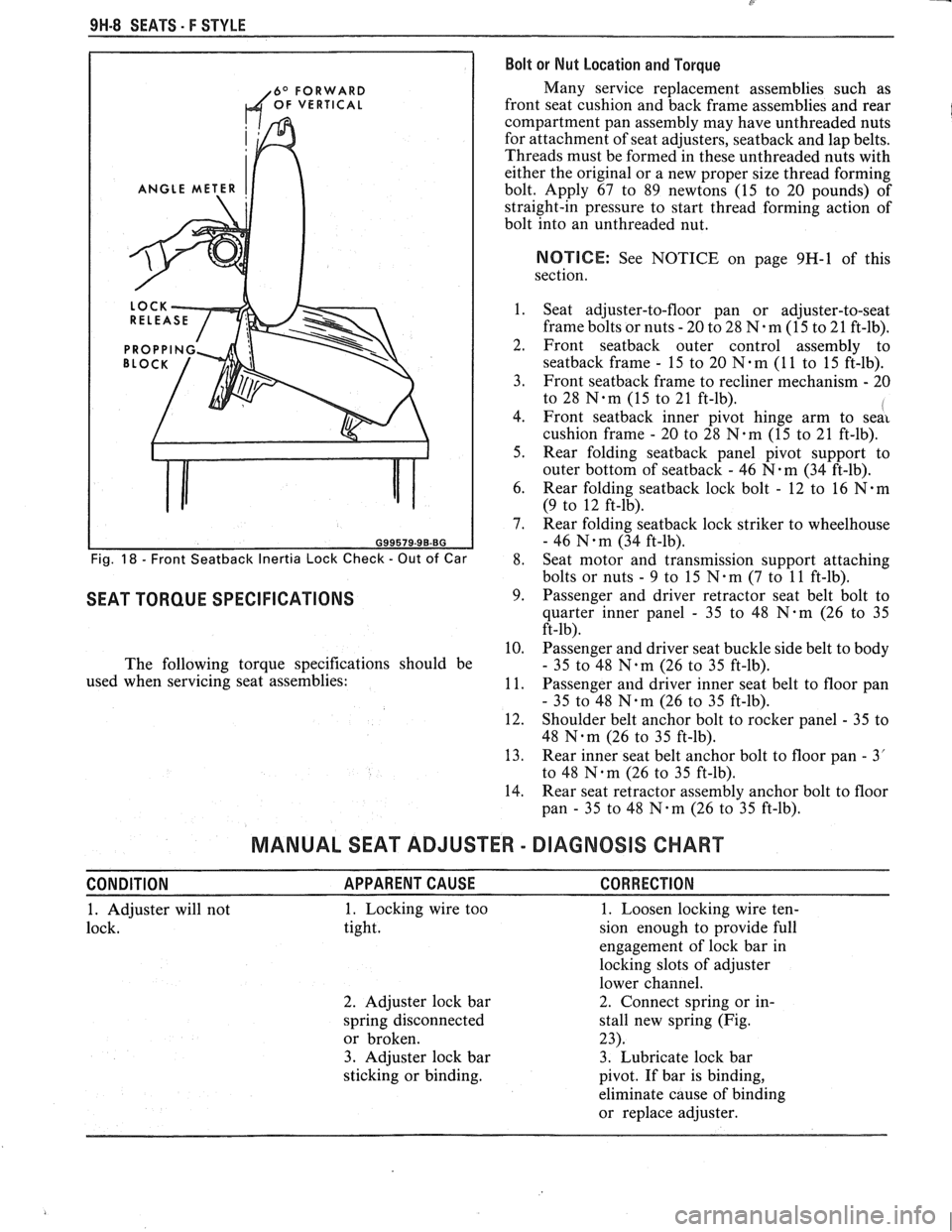
9H-8 SEATS. F STYLE Bolt or Nut Location and Torque
6O FORWARD Many service replacement assemblies such as
OF VERTICAL front seat cushion and back frame assemblies and rear
compartment pan assembly may have unthreaded nuts
for attachment of seat adjusters,
seatback and lap belts.
Threads must be formed in these unthreaded nuts with
either the original or a new proper size thread forming
ANGLE METER bolt. Apply 67 to 89 newtons (15 to 20 pounds) of
straight-in pressure to start thread forming action of
bolt into an unthreaded nut.
NOTIICE: See NOTICE on page 9H-1 of this
section.
1. Seat adjuster-to-floor pan or adjuster-to-seat
frame bolts or nuts
- 20 to 28 N-m (15 to 21 ft-lb).
2. Front seatback outer control assembly to
seatback frame - 15 to 20 N-m (1 1 to 15 ft-lb).
3. Front
seatback frame to recliner mechanism - 20
to 28
N-m (15 to 21 ft-lb). I 4. Front seatback inner pivot hinge arm to seai
cushion frame - 20 to 28 N.m (15 to 21 ft-lb).
5. Rear folding
seatback panel pivot support to
outer bottom of
seatback - 46 N-m (34 ft-lb).
6. Rear folding
seatback lock bolt - 12 to 16 N.m
(9 to 12 ft-lb).
7. Rear folding
seatback lock striker to wheelhouse
- 46 N.m (34 ft-lb).
Fig. 18 - Front Seatback Inertia Lock Check - Out of Car 8. Seat
motor and transmission support attaching
bolts or nuts
- 9 to 15 N.m (7 to 11 ft-lb).
SEAT TORQUE SPECIFICATIONS 9. Passenger and driver retractor seat belt bolt to
quarter inner panel
- 35 to 48 N-m (26 to 35
ft-lb).
10. Passenger and driver seat buckle side belt to body
The following torque specifications should be
- 35 to 48 N.m (26 to 35 ft-lb).
used when servicing seat assemblies:
11. Passenger and driver inner seat belt to floor pan
- 35 to 48 N.m (26 to 35 ft-lb).
12. Shoulder belt anchor bolt to rocker panel
- 35 to
48
Nam (26 to 35 ft-lb).
13. Rear inner seat belt anchor bolt to floor pan
- 3'
to 48
Nqm (26 to 35 ft-lb).
14. Rear seat retractor assembly anchor bolt to floor
pan
- 35 to 48 N-m (26 to 35 ft-lb).
MANUAL SEAT ADJUSTER - DIAGNOSIS CHART
CONDITION APPARENTCAUSE CORRECTION
1. Adjuster will not 1. Locking wire
too
1. Loosen locking wire ten-
lock. tight. sion enough to provide full
engagement of lock bar in
locking slots of adjuster
lower channel.
2. Adjuster lock bar 2. Connect spring or
in-
spring disconnected stall new spring (Fig.
or broken. 23).
3. Adjuster lock bar 3. Lubricate lock bar
sticking or binding.
pivot. If bar is binding,
eliminate cause of binding
or replace adjuster.
Page 1802 of 1825
SEATS - F STYLE 9H-19
4. Pump/motor assembly (2).
5. Solenoid valve (1).
Install or Connect
Install reverse of removal procedures.
Recliner Assembly
Remove or Disconnect
1. Switch assembly (ref. Switch Assembly
procedures).
2. Outer finish panel (29, Fig. 28).
3. Head
restraint (ref. Head Restraint procedures).
4. Boot (12)
5. Screws from underside of seatback outer panel
(13) and remove panel.
6. Upper
and lower bolts securing recliner assembly
I (38) to seatbaek frame (16) and cushion frame
(37).
REAR SEATS
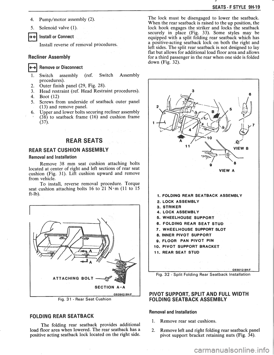
REAR SEAT CUSHION ASSEMBLY
Removal and Installation
Remove 38 mm seat cushion attaching bolts
located at center of right and left sections of rear seat
cushion (Fig. 31). Lift cushion upward and remove
from vehicle.
To install, reverse removal procedure. Torque
seat cushion attaching bolts 16 to 21
N-m (11 to 15
ft-lb).
ATTACHING BOLT
I SECTION A-A I
Fig. 3 1 - Rear Seat Cushion
FOLDING REAR SEATBACK
The folding rear seatback provides additional
load floor area when lowered. The rear
seatback has a
positive acting
seatback lock located on the right side. The
lock must be disengaged to lower the seatback.
When the rear
seatback is raised to the up position, the
lock hook engages the striker and locks the
seatback
securely in place (Fig. 33). Some styles may be
equipped with a split folding rear
seatback which has
a positive-acting
seatback lock on both the right and
left sides. The split rear
seatback is not designed to lay
flat but allows for additional load floor area and allows
for a third passenger in the rear when one side is folded
down (Fig. 32).
VIEW A
1. FOLDING REAR SEATBACK ASSEMBLY
2. LOCK ASSEMBLY
3. STRIKER
4. LOCK ASSEMBLY
5. WHEELHOUSE SUPPORT
6. FOLDING REAR SEAT STUD
7. WHEELHOUSE SUPPORT SLOT
8. INNER PIVOT SUPPORT
8. FLOOR PAN PIVOT PIN
10. PIVOT SUPPORT BRACKET
11. REAR SEAT STUD
Fig. 32 - Split Folding Rear Seatback lnstallation
PIVOT SUPPORT, SPLIT AND FULL WIDTH
FOLDING SEATBACK ASSEMBLY
Removal and Installation
1. Remove rear seat cushions.
2. Remove left and right folding rear
seatback panel
pivot support bracket retaining nuts (Fig. 34).
Page 1823 of 1825
8- CHASSIS INDEX
Recommended Fluids and Lubricants ................ OB-6
Relay Rod
......................................................... 3B6-2
Remote Mirror Control
...... See Body Service Section
5H.1. 15
Repair Procedures
.......................................... 88-50
S
........................................ Scheduled Maintenance OB- 1
Seats (Power) ....................................... Lumbar Support 8A- 145-0
............................. Sequential Fuel Injection 6E3-C2- 1
Service Engine Soon Light
.................................... 8C-3
Sheet Metal and Grille
................................ Section 2C
......................................... General Description .2 C. 1
........................................... Service Procedures .2 C. 1
................................................................. Hood .2 C. 1
...................................................... Hood Hinge 2C-2
Hood Latch and Cable
...................................... 2C-2
Paint
.............................................. Color Matching 2C-5
................................................ Identification -32-6
Interior Plastic Parts ...................................... 2C-6
................................................ Shock Absorbers 3D-
1
Shoe and Lining Assembly
. Brake
............................................ 3000/3 100 Series 5B1-3
3548 Series ...................................................... 5B6-4
Side Marker Lights
.............................................. 8B-2
........ Speakers See 8A- 150-0 & Body
Manual Section
6H- 1
.................... Spark Plug Gap .. .................. 6E3-13-3
................................ Speaker and Speaker Grille 9A-9
Special Tools
............................................ Air Conditioning 1 B-3 5
Air Conditioning Compressor
................................................. Overhaul 1D1-21
........................ Automatic Transaxle AT-700-R4-64
................................................................ Brakes SF-1
Clutch ................................................................ 7C-8
................................................................ Rear 4B1-20
....................................... Rear (Borg Warner) 4B-20
........................... Driveability and Emissions .6 E. 17
................................................ Engine Cooling 6B- 14
Power Steering Pump
& Gear ...................... 3B7-17
............................................... Propeller Shaft .4 A. 12
Steering Wheels and Columns
.......................... 5-35
Specifications Automatic Transmission Unit
............................................ Repair AT-700-R4-59
..................................................... Battery 6D 1-7
................................................................ Brakes 5F-1
Bumpers
......................................................... 2B-5
Charging System
................ .. ................... 6D3-3
.............................................................. Clutch .7 (2.8
....................................... Cranking System 6D2- 1 1
Driveability and Emissions ............................ 6E-23
................................................ Engine (V-6) ..6A 2.26
Engine (V-8) .................................................. 683-28
........................................ Front Suspension 3C- 10
Power Steering Gear and Pump
.................. 3B7-18 ............................................. Propeller Shaft .4 A. 12 ........................................................ Rear Axle 4B-19 ............................ Rear Axle (Borg Warner) 4B 1- 19
Rear Suspension
.............................................. 3D-9
.......................................... Replacement Bulbs 8Br 10 .............................................. Steering Linkage 3B6-6
Steering Wheels and Columns
...................... 3B5-35
........................................ Wheel Alignments 3A-4
....................................................... Speedometer 8C-2
........................................ Speedometer (Removal) 8C-5
...................................................... Speed Sensors 8C-1
Starter ........................................ Section 6D2. 8A-30-0
............................................. Starter (Circuit) 8A-30-0
Steering Linkage ...................................... Section 3B6
....................................... General Description 3B6-1
........................ Maintenance and Adjustments 3B6-1
................................................ On-Car Service 3B6-2
..................................................... Idler Arm 3B6-4
................................................ Pitman Arm 3B6-5
.................................................... Relay Rod 3B6-3
Tie Rods
...................................................... 3B6-2
.................................................. Specifications 3B6-6
Steering, Suspension, Tires and
Wheels Diagnosis
............................................................. 3-1
Steering Wheels and Columns
............................ 3B5-1
..................................... General Information 3B5- 1
Maintenance and Adjustments
...................... 3B5-'
On-Car Service .............................. .. ........... 3B5
Checking for Accident Damage
.................. 3B5-5
Intermediate Shaft ............... .. .................... 3B5-3
Park Lock Cable .......................................... 3B5-4
Standard Column
............................. Automatic Transaxle 3B5-13
Manual Transaxle ................................. 3B5- 19
Tilt Column
.............................. Automatic Transaxle 3B5-27
.................................. Manual Transaxle 3B5-19
Unit Repair Intermediate Shaft
...................................................... Assembly 3B5-6
................................................. Special Tools 3B5-35
Torque Specifications
.................................... 3B5-35
............................................. Starting System 8A-30-0
........................................ Strut Assembly (Front) 3C-4
.................................... ..... Symbols Chart ... 8A-3-0
T
.......................................................... Tachometer 9G-1
Tail/Stop/Turn Signal/Lights .......................... 8B-2
Temperature Cable
.............................................. 112 A-
Temperature Warning Light ................................ 8C-3
Theft Deterrent (Circuit)
.............................. 8A-133-0
Tie Rods
.............................................................. 3B6-2
Tires and Wheels
........................................ Section 3E
Diagnosis
.................................................. Section 3
General Information
......................................... 3E-1
................................................... Metric Tires 3E-2
....................................... Replacement Tires .31 E-
.................................................... Tire Placard 3E-2
........................................................... Wheels 3E-2
Maintenance and Adjustments
.......................... 3E-2
.......................... Aluminum Wheel Cleaning 3E-9
............................. ......... Inflation of Tires .. 3E-3
........................................ Tire Chain Usage 3E-4
.................................................. Tire Rotation 3E-3
.............................................. Wheel Repair 3E-2
...................................... Wheel Studs/Nuts 3E-3
........................................... Service Operations 3E-4
........................ Aluminum Wheel Cleaning 3E-9
.................................... Balance Precautions 3E-7
............................ Balancing Tire and Wheel 3E-7
.............................................. Compact Spare 3E-6
........................ Correcting Nonuniform Tires 3E-8