1988 PONTIAC FIERO compression ratio
[x] Cancel search: compression ratioPage 870 of 1825

DRIVEABILITY AND EMISSIONS S.OL (VIN F) & 5.7L (VIN 8) 6E3-B-5
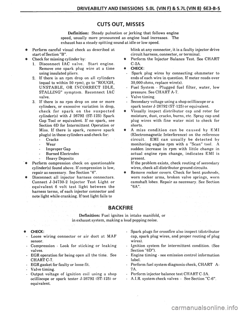
Definition: Steady pulsation or jerking that follows engine
speed, usually more pronounced as engine load increases. The
exhaust has
a steady spitting sound at idle or low speed.
@ Perform careful visual check as described at blink
at any connector, it is a faulty injector drive
start of Section
"B". circuit harness, connector, or terminal.
@ Check for missing cylinder by: @ Perform the Injector Balance Test. See CHART
1. Disconnect IAC valve. Start engine. C-2A.
Remove one spark plug wire at a time
@ CHECK:
using insulated pliers. - Spark plug wires by connecting ohmmeter to
2. If there is an rpm drop on all cylinders ends
of each wire in question. If meter reads over
(equal to within
50 rpm), go to "ROUGH, 30,000
ohms, replace wire(s).
UNSTABLE, OR INCORRECT IDLE, - Fuel System - Plugged fuel filter, water, low
STALLING" symptom. Reconnect IAC pressure. See CHART A-7.
valve.
- Valve timing.
3. If there is no rpm drop on one or more - Secondary voltage using a shop ocilliscope or a
cylinders, or excessive variation in drop, spark tester 5-26792 (ST-125)
or equivalent.
check for spark on the suspected
@ Visually inspect distributor cap and rotor for
cylinder(s) with J 26792 (ST-125) Spark moisture, dust, cracks, burns, etc. Spray cap and
Gap Tool or equivalent. If no spark, see plug wires with fine water mist to check for
Section 6D for Intermittent Operation or shorts.
Miss. If there is spark, remove spark
@ A miss condition can be caused by EM1
plug(s) in these cylinders and check for: (Electromagnetic Interference) on the reference
- Cracks circuit. EM1 can usually be detected by
- Wear monitoring engine rpm with a "Scan" tool. A
- Improper Gap sudden
increase in rpm with little change in
- Burned Electrodes actual engine rpm change, indicates EM1 is
- Heavy Deposits present.
@ Perform compression check on questionable If
the problem exists, check routing of secondary
cylinder(s) found above. If compression is low, wires, check
all distributor ground circuits.
repair as necessary. See Section
"6". @ Remove rocker covers. Check for bent pushrods,
@ Disconnect all injector harness connectors. worn
rocker arms, broken valve springs, worn
Connect
5-34730-2 Injector Test Light or camshaft
lobes. Repair as necessary. See Section
equivalent 6 volt test light between the
"6A".
harness terms, of each injector connector and
note light while cranking. If test light fails to
BACKFIRE
Definition: Fuel ignites in intake manifold, or
in exhaust system, making a loud popping noise.
@ CHECK: - Spark plugs for crossfire also inspect (distributor
- Loose wiring connector or air duct at MAF
cap, spark plug wires, and proper routing of plug
sensor. wires).
- Compression - Look for sticking or leaking - Ignition system for intermittent condition. (See
valves. Section
"6D").
- EGR operation for being open all the time. See - Engine timing - see emission control information
CHART C-7. label.
- EGR gasket for faulty or loose fit. - Perform fuel system diagnosis check, CHART A-
- Valve timing. 7A.
- Output voltage of ignition coil using a shop - Perform injector balance test CI-IART C-2A.
ocilliscope or spark tester 5-26792 (ST-125) or
- A.I.R. system check valves - See Section "C-6".
equivalent.
Page 871 of 1825

6E3-B-6 5.OL (VIN F) & 5.7L (VIN 8) DRIVEABILITY AND EMISSIONS
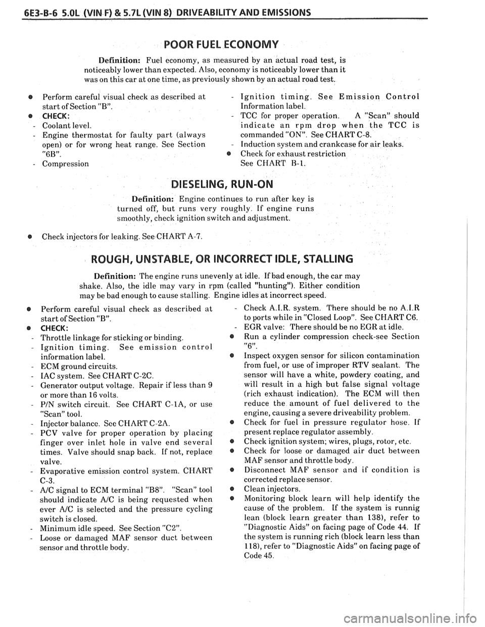
POOR FUEL ECONOMY
Definition: Fuel economy, as measured by an actual road test, is
noticeably lower than expected. Also, economy is noticeably lower than it
was on this car at one time, as previously shown by an actual road test.
@ Perform careful visual check as described at
start of Section "B".
@ CHECK:
- Coolant level.
- Engine thermostat for faulty part (always
open) or for wrong heat range. See Section
"6B".
- Compression
- Ignition timing. See Emission Control
Information label.
- TCC for proper operation. A "Scan" should
indicate an rpm drop when the TCC
is
commanded "ON". See CHART C-8.
- Induction system and crankcase for air leaks.
@ Check for exhaust restriction
See CHART
B-1.
DIESELING, RUN-ON
Definition: Engine continues to run after key is
turned off, but runs very roughly. If engine runs
smoothly, check ignition switch and adjustment.
@ Check injectors for leaking. See CHART A-7.
ROUGH, UNSTABLE, OR INCORRECT IDLE, STALLING
Definition: The engine runs unevenly at idle. If bad enough, the car may
shake. Also, the idle may vary in rpm (called "hunting"). Either condition
may be bad enough to cause stalling. Engine idles at incorrect speed.
@ Perform careful visual check as described at
start of Section "B".
e CHECK:
- Throttle linkage for sticking or binding.
- Ignition timing. See emission control
information label.
- ECM ground circuits.
- IAC system. See CHART C-2C.
- Generator output voltage. Repair if less than 9
or more than 16 volts.
- PIN switch circuit. See CHART C-lA, or use
"Scan" tool.
- Injector balance. See CHART C-2A.
- PCV valve for proper operation by placing
finger over inlet hole in valve end several
times. Valve should snap back. If not, replace
valve.
- Evaporative emission control system. CHART
C-3.
- A/C signal to ECM terminal "B8". "Scan" tool
should indicate
AIC is being requested when
ever
A/C is selected and the pressure cycling
switch is closed.
- Minimum idle speed. See Section "C2".
- Loose or damaged MAF sensor duct between
sensor and throttle body. Check
A.I.R. system. There should be no
A.1.R
to ports while in "Closed Loop". See CHART C6.
EGR valve: There should be no EGR at idle.
Run
a cylinder compression check-see Section
"6".
Inspect oxygen sensor for silicon contamination
from fuel, or use of improper RTV sealant. The
sensor will have a white, powdery coating, and
will result in a high but false signal voltage
(rich exhaust indication). The ECM will then
reduce the amount of fuel delivered to the
engine, causing a severe driveability problem.
Check for fuel in pressure regulator hose. If
present replace regulator assembly.
Check ignition system; wires, plugs, rotor, etc.
Check for loose or damaged air duct between
MAF sensor and throttle body.
Disconnect MAF sensor and if condition is
corrected replace sensor.
Clean injectors.
Monitoring block learn will help identify the
cause of the problem. If the system is runnig
lean (block learn greater than 1381, refer to
"Diagnostic Aids" on facing page of Code
44. If
the system is running rich (block learn less than
1 181, refer to "Diagnostic Aids" on facing page of
Code
45.
Page 1120 of 1825

AUTOMATIC TMNSMISSION ON-VEHICLE SERVICE 7A1-1
SECTION 7Al
AUTOMAT C TRANSM
ON VEH CLE SERV
CONTENTS
GENERAL SERVICE T.V. Cable
PROCEDURES Diagnosis ........................ .. ....................... 7A 1-6
Parts Cleaning, Inspection and
Replacement
....................................... 7A1-7
Replacement
............................ ... .... 7A1- 1 Adjustment ............................................. 7A1-7
Flexplate/Torque Converter Changing Fluid and Filter ............................. 7A1-7
........................... Vibration Test Procedure 7A1-2 700-R4 Serviceable Components
Fluid Leak Diagnosis
..................................... 7A 1-2
Servo Assembly .......................................... 7A 1-7
Methods For Locating Leaks
.................... 7Al-2 Speedometer Drive Gear .............................. 7A 1-1 1
Repairing the Leak .................................. 7A 1-2 Spccdomctcr Driven Gciu .......................... 7A1-1 1 Possible Points of Fluid Leaks .................. 7A1-2 Governor ............................................. 7A 1- 1 1
Case Porosity Repair .................................. 7A 1-3 Filler Tube .............................................. 7A1-12
Torque Converter Clutch
Pressure Regulator Valve
........................... 7A 1- 12
Electrical Controls
.................................. 7Al-3
Auxiliary Valve Body ................................. 7A1-13
Diagnosis
................................... .... ........ 7A 1-3 Valve Body ............................................. 7A 1- 13
ON-VEHICLE SERVICE Rear Oil Seal ............................................ 7A 1- 14
Shift Control Cable
Oil Cooler Lines And Fittings
................... 7A1-14
Replacement
............................................ 7A 1-3 Oil Cooler Flushing .............................. 7A 1 - 14 ................................................ Adjustment 7A1-3 Transmission Assenlbly Removal and
Floor Shift Control
................... .. ................ 7A1-3
Installation ........................... .. ............ 7A1- 14
Park/Lock Control Cable .............................. 7A 1-4
Park/Neutral and Back Up Lamp
Switch
................................................. 7A1-5
GENERAL SERVICE PROCEDURES
PARTS CLEANING, INSPECTION AND
REPLACEMENT
Use appropriate safety equipment such as:
- Safety glasses
- Safety shoes
- Gloves
Keep work area and tools clean
Clean transmission exterior before removing
parts
Do not use wipe cloths or rags
Do not use solvents on:
- Rubber seals
- Plastic/Teflon@ thrust washers
Blow out all passages with compressed air
Clean out small passages with fine wire
Handle parts carefully to prevent damage
Lubricate all internal parts with transmission
fluid during assembly
When installing screws, bolts or studs into
aluminum always dip the threads in transmission
fluid
Always use a torque wrench for proper torque
€3 Recondition damaged or stripped aluminum
threads with thread inserts
@ Replace all gaskets and o-ring seals
- Do not use gasket cement or sealers
@ Replace Teflon@ and rubber lip seals only when
necessary and install using the appropriate seal
protector
s Manual linkage for:
- Wear at pivoting points - Bent or broken links and rods
s All seals, gaskets, o-rings and mating surfaces for:
- Nicks
- Cuts
- Damage
€3 Snap rings for:
- Expansion or compression
- Distortion
- Nicks
- Proper ring to groove fit
s Bearings and thrust surfaces for:
- Wear
- Scoring
Page 1817 of 1825

2 - CHASSIS INDEX
Backup Lamp Switch (Circuit) .......... 8A- 1 12. 7A 1-5
Backup Lights
..................................................... 8B-1
...................................................... Battery Section 6D 1
............................ Battery Specification Chart 6D 1-7
.................................... Body Identification ... .... OA- 1
Borg Warner Rear Axle .......................... Section 4B1
...................................................... Blower Motor 1A-14
Blower Switch
.................................................... 1 A- 13
Booster Assembly
............................................. 5D2-2
Brakes
- General ......................................... Section 5
Adjustment
.................................................... 5C3-4
Booster Assembly
. Tandem
Diaphragm
................... .... ..................... 5D2- 1
................................................ Components 5C3- 1
Diagnosis and Inspection
................................. 5-3
Disc Brake Caliper Assembly
.................................................... 3548 Series 5B6-1
Drum Brake Assembly ........................ Section 5C3
General Description
.......................................... 5-2
On-Car Service
.................................................... 5-7
Specifications & Special Tools ......................... .5 F. 1
...................................................... Unit Repair 5A3- 1
.......................................... Warning System 8A-4 1-0
............ Brake Pedal Mounting .. ......................... 5-1 7
Bulb Usage Chart
............................................ 8B-10
............................................ Bumpers Section 2B,3 D.6
Bumper Energy Absorbing Units
.................... 2B-2
Bench Testing
................................................ 2B-3
........................................ Damage/Leakage 2B-3
................................ Removal After Collision 2B-2
............................................. Fascia Rub Strips .2 B. 1
.................................................... Front Bumper 2B-2
Assembly
........................................................ 2B-4
Energy Absorber
........................................... 2B-4
............................................................. Fascia .2 B. 1
On-Vehicle Service
...................................... 2B-4
Rear Bumper
.................................... .... ............ 2B-2
........................................................ Assembly 2B-5
Energy Absorber
............................................ 2B-4
............. .................... Fascia Molding Strip .. 2B-5 ........................................... Service Procedures .2 B. 1
.................................................. Specifications 2B-5
C
Caliper Assembly . Disc Brake
.............................................. 3000/3 100 Series 5B 1-2
3548 Series
...................................................... 5B6-2
Caliper Overhaul
....................... 3000/3 100 Series .. ............... 5B 1-4
3548 Series
.................................................... 5B6-5
Caster and Camber Adjustment
........................ 3A- 1
............................................. Catalytic Converter 6F-2
Center High-Mounted Stoplight
....................... ... 8B- 1
Charging System
...................... 8A.30.7, Section 6D3
Chassis Electrical
.................................... Section 8B
Center High Mounted Stoplight
...................... 8B-1 ................................. Exterior Light Monitor .8 B. 1
................................................................ Chimes 8A-77
................................ Cigar Lighter (Circuit) 8A- 1
14-0
.............................. Circuit Breaker Details Section 8A
Power ACC Circuit Breaker .... 8A- 10.1.10.3.10.5.
11-3
.... Window Circuit Breaker 8A~10~1,10~3.10~5.1 1.4
Clutch
........................................................ Section 7C
......................................... General Description .7 C. 1 ........................................................... Diagnosis 7C-2 Bleeding
Hydraulic Clutch System
................. .7 C.2
Preliminary Checks ..................................... ... 7C-2
On-Vehicle Service
........................................... 7C-5
Clutch Hydraulic System
.................................. 7C-5
Clutch Pedal ...................................................... 7C-6
Pilot Bearing
..................................................... 7C-6
Pressure Plate and Disc
.................................... 7C-6
Special Tools
......................... ....... ................ 7C-8
Specifications
................................................... 7C-8
Coil Springs and Insulators .............................. 3D-1
Component Fluid Capacities
................................ OB-6
Component Location Views
........................ 8A-201-0
Composite Master Cylinder
................... Section 5A3
Compression Test
.................. .. ............................. 6-5
Condenser Mounting
....................................... 1B 1-24
Connectors
.................................................... 8A-202-0
Coolant Fan Temperature Switch
...................... 8A-3 1
Cooling and Radiator
................................ Section 6B
Cooling System Capacities
................................. OB-6
Cooling System Diagnosis
.................................... 6B-3
Cranking System
...................................... Section 6P*
Diagnosis ..................................................... 6~2
General Description ................................ 6D2- 1
Cranking System
........................................ 6D2- 1
Solenoid
................................................... 6D2- 1
Starter Motor ......................................... 6D2-1
On-Vehcile Service
...................................... 6D2-4
Specifications
............................................ 6D2- 1
Starter
........................................................ 6D2-4
Unit Repair
............................................ 6D2-6- 11
Service Procedures
...................................... 6D2-3
Cruise Control
.............................. 8A-34-0, Section 9B
Diagnosis
............................................................ 9B-4
Cruise Set Speed High or Low
.................... 9B-4
Cruise System Surges
.................................. 9B-4
Cruise Tap-Up and Tap-Down
...................... 9B-4
Excessive Cruise Speed Loss on
Hills
........................................................... 9B-4
General Description
........................................ 9B-1
Electrical and Vacuum Release
Switches
...................................................... 9B-4
Electrical Harness
.......................................... 9B-A
Electronic Controller (Module) .................... 9B .
Off/On/Resume/Accel Switch
Operation
.................................................. .91 B-
Servo Unit
.................................................... 9B-2
Set/Coast Button Switch .............................. 9B-1
................................................ Speed Sensors 9B-3
Vacuum Supply
............................................ 9B-4
On-Car Service
.................................................. 9B-6
................................ Cruise Release Switches 9B-6
.......................................... Servo Mounting 9B-10
Vacuum Harness and Cable Routing
VIN
E ................................. .. .................. 9B,7
.................................................... VIN F, 8 9B-9
....................................................... VIN S 9B-8
........................ Vacuum Tank - VIN S,F,E, 9B-10
.............................. Cruise Control (Circuit) 8A-34-0
D
......................................... Defogger (Circuit) $A-6 1-0
..................... ...... Defroster Duct Assembly ... .812 C-
Diagnosis
Air Conditioning
- General ........................... 1B-5
.................... Automatic Transmission - General 7A
Automatic Transmission
- ................ HD-700-R4-2