1988 PONTIAC FIERO Windshield
[x] Cancel search: WindshieldPage 2 of 1825
1988
SER
This manual applies to the 1988 Pontiac Firebird Models.
It contains the latest product information available at the
time of publication approval. lnformation pertaining to
the operation of the vehicle is contained in the Owner's
Manual which accompanies each vehicle. The right is
reserved to make changes at any time without notice.
Any references to brand names in this manual is intended
merely as an example of the types of
lubricant% tools,
materials, etc, recommended for use in servicing 1988
Pontiac Models. In all cases, an equivalent may be used.
PONTIAC DIVISION
GENERAL
MOTORS CORPORATION
PONTIAC, MICHIGAN 48053
1987 General Motors Corp. All Rights Reserved.
No part of this publication may be reproduced, stored in any
retrieval system or transmitted in any form or by any means,
including but not limited to electronic, mechanical,
photocopying, recording or otherwise, without the prior written
permission of General Motors Corp. This includes all text,
illustrations, tables and charts.
S-881 OF 9-87 Printed in Canada
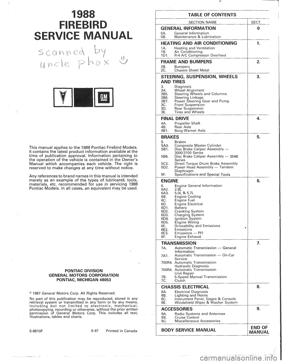
TABLE OF CONTENTS
SECTION NAME
GENERAL INFORMATION
OA. General lnformation
OB. Maintenance & Lubrication
1 SECT.
HEATING AND AIR CONDITIONING
1A. Heating and Ventilation
1 B. Air Conditioning
1D1. R-4 AIC Com~ressor Overhaul
FRAME AND BUMPERS
2B. Bumpers 2C. Chassis Sheet Metal
STEERING, SUSPENSION, WHEELS
AND TIRES
3. Diagnosis
3A. Wheel Alignment
3B5. Steering Wheels and Columns 3B6. Steering Linkage 3B7. Power Steering Gear and Pump
3C. Front Suspension
3D. Rear Suspension
3E. Tires and Wheels
FINAL DRIVE
4A. Propeller Shaft
4B. Rear Axle
4B1. Bora-Warner Axle
BRAKES 5. Brakes 5A3. Comoosite Master Cvlinder 5B1. Disc r rake Caliper ~ssembly - 300013100 Series 5B6. Disc Brake Caliper Assembly - 3548
Series
5C3. Direct Torque Drum Brake Assembly 5D2. Power Head Assembly - Tandem Diaohraam 5F. ~~ecifications and Special Tools
ENGINE 6. Engine General lnformation 6A2. 2.8L 6A3. 5.OL & 5.7L 6B. Engine Cooling
6C. En~ine Fuel
6D. ~ngine Electrical 6D1. Battery 6D2. Cranking System 6D3. Charging System 6D4. Ignition System 6D5. Engine Wiring
6E. Driveabilitv and Emissions
6E2. ~missions' 6E3. Emissions - PFI
6F. Engine Exhaust
TRANSMISSION 7A. Automatic Transmission - General
lnformation
7A1. Automatic Transmission - On-Car
Service
700R4. Automatic Transmission Hydraulic Diagnosis
700R4. Automatic Transmission Unit Repair
76. 5-Speed Manual Transmission
7C. Clutch
CHASSIS ELECTRICAL 8A. Electrical Diagnosis
8B. Lighting and Horns
8C. Instrument
Panel, Gages
& Console
8E. Windshield Wiper &Washer System
ACCESSORIES 9A. Radio Systems and Antennas 9B. Cruise Control 9G. Miscellaneous Accessories
I BODY SERVICE MANUAL END
OF
MANUAL
Page 4 of 1825
GENERAL INFORMATION OA-1
SECTION (DA
GENERAL NFORMAT
CONTENTS
................................... General Description OA- 1 Prevailing Torque Fasteners ......................... OA-2
...................................... Body Number Plate OA- 1 Recommendations For Fastener Reuse ........ OA-2
..................... Vehicle Identification Number OA- 1 Vehicle Lifting Procedures ............ ., ............. OA-2
......................................... Metric Fasteners OA- 1 Precautions Against Tipping ........................ OA-7
................... Fastener Strength Identification OA-2 Automotive Abbreviations ................... .... 0.4- 1 1
GENERAL DESCRIPTION
Only general information appears in this section. left
of the windshield, see Figure 2. Refer to Figure 3
Detailed specifications on major units are given at the for detailed "VIN" code information.
For Engine V.I.
end of each respective section of this manual. N. Location, refer to Figure
4.
BODY NUMBER PLATE METRIC FASTENERS
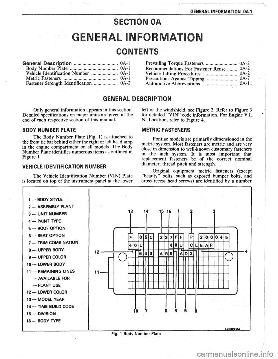
The Body Number Plate (Fig. 1) is attached to
Pontiac models are primarily dimensioned in the
the front tie bar behind either the right or left
headlamp metric system, Most fasteners are metric and are very in the engine On The close in dimension to well-known customary fasteners Number Plate identifies numerous items as outlined in in the inch system. It is most important that Figure 1. re~lacement fasteners be of the correct nominal
VEHICLE IDENTIFICATION NUMBER d&meter, thread pitch and strength.
Original equipment metric fasteners (except
The Vehicle Identification Number (VIN) Plate "beauty" bolts, such
as exposed bumper bolts, and
is located on top of the instrument panel at the lower cross
recess head screws) are identified by a number
1 -- BODY STYLE
2 ASSEMBLY PUNT
3 -- UNIT NUMBER
4 -- PAINT TYPE
5 - ROOF OPTION
6 -- SEAT OPTION
7 - TRIM COMBINATION
8 - UPPER BODY
9 - UPPER COLOR
10 -- LOWER BODY
11 - REMAINING LINES
- AVAILABLE FOR
--PLANT
USE
12 - LOWER COLOR
13 - MODEL YEAR
14 -- TIME BUILD CODE
15 - DIVISION
16 - BODY TvPE
6200224A
Fig. 1 Body Number Plate
Page 21 of 1825
OB-4 MAINTENANCE AND LUBRICATION
Tire and wheel operation - Be alert to a vibra-
tion of the steering wheel or seat at normal highway
speeds. This may mean a wheel balance is needed. Also, a
pull right or left on a straight, level road may show the
need for
a tire pressure adjustment or wheel alignment.
Steering system operation - Be alert to
changes in steering action. An inspection is needed when
the steering wheel is harder to turn or has too much free
play or if unusual sounds are noted when turning or
parking.
Headlight aim operation - Take note of light
pattern occasionally. If beam aim doesn't look right,
headlights should be adjusted.
AT EACH FUEL FILL
Engine oil level check - Check engine oil level
and add if necessary. See your Owner's
Manual for further
details.
NOTICE: A large loss in this system may indicate a
problem. Have it inspected and repaired at once.
Engine coolant level and condition - Check
engine coolant level in coolant reservoir tank and add if
necessary. Replace if dirty or rusty. See your Owner's
Manual for further details.
NOTICE: A large loss in this system may indicate a
problem. Have it inspected and repaired at once.
Windshield washer fluid level check -- Check
washer fluid level in container and add if necessary.
Hood latch operation - When opening hood on
cars equipped with hoods that open from the front, note
the operation of secondary latch. It should keep hood from
opening all the way when primary latch is released. Make
sure that hood closes firmly.
AT LEAST MONTI-ILY
Tire and wheel inspection and pressure
check--
Check tires for abnormal wear or damage. Also,
check for damaged wheels. Keep pressures as shown on
Tire Placard on the driver's door (include spare unless it is
a stowaway). Pressure should b\: checked when tires are
"cold". See "Tires" in Owner's Manual for further
infomation.
Light operation check - Check operation of
license plate light, side-marker lights, headlights includ-
ing high beams, parking lights, taillights, brake lights.
turn signals, backup lights, instrument panel and interior
lights and hazard warning flashers.
Fluid leak check - After the car has been parked
for a while, inspect the surface beneath the car for water,
oil, fuel or other fluids. Water dripping from the air
conditioning system after use is normal. If you notice fuel
leaks or fumes, the cause should be found and corrected at
once.
AT LEAST TWICE A YEAR (FOR EXAMPLE,
EVERY SPRING AND FALL)
Power steering pump fluid level check --
Check power steering pump fluid level in accordance with
Owner's Manual instructions and keep at proper level.
NOTICE: A large loss in this system may indicate a
problem. Have it inspected and repaired at once.
Brake master cylinder reservoir fluid level
check ---- Check fluid and keep at proper level. Note: It is
normal for the brake fluid level to go down slightly as the
brake pads wear
- so be sure to keep reservoir filled.
NOTICE: A large loss in this system may indicate a
problem. Have
it inspected and repaired at once.
Clutch system service --- manual transmis-
sionltransaxle --- For cars equipped with hydraulic
clutch system, check the reservoir fluid level and add fluid
as required. All others, check clutch pedal free travel and
adjust as necessary. See your Owner's Manual for further
details.
~
NOTICE: A large loss in this system may indicate a
problem. Have it inspected and repaired at once.
Weatherstrip Lubrication - Clean surface and
then apply a thin film of silicone grease with a clean cloth.
EACH TIME OIL IS CHANGED
Automatic and manual transmissionltrans-
axle fluid level check - Check transmission/transaxle
fluid level and add as required. (Corvette only) if equipped
with manual transmission
- check fluid in the overdrive
unit and add as required.
NOTICE: A large loss in this system may indicate a
problem. Have
it inspected and repaired at once.
Brake systems inspection - For convenience,
the following should be done when wheels are removed
for rotation: Inspect lines and hoses for proper hookup,
binding, leaks, cracks, chafing, etc. Inspect disc brake
pads for wear and rotors for surface condition. Also in-
spect drum brake linings for wear and cracks. Inspect
other brake parts, including drums, wheel cylinders, park-
ing brake, etc. at the same time. Check parking brake
adjustment.
INSPECT BRAKES MORE OFTEN IF DRIVING
HABITS OR CONDITIONS RESULT IN FREQUENT
BRAKING.
Steering, suspension and front drive axle
boot and seal inspection
- Inspect front and rear
suspension and steering system for damaged, loose or
missing parts, signs of wear or lack of lubrication. Inspect
power steering lines and hoses for proper hookup, bind-
ing, leaks, cracks, chafing, etc. (On cars equipped with
manual steering gear, check for seal leakage.) On
front-
wheel-drive cars, clean then inspect drive axle boot seals
for damage, tears or leakage. Replace seals if necessary.
Exhaust system inspection - Inspect complete
system. Inspect body near the exhaust system. Look for
broken, damaged, missing or out-of-position parts as well
as open seams, holes, loose connections or other condi-
tions which could cause a heat buildup in the tloor pan or
could let exhaust fumes seep into the trunk or passenger
compartment.
Page 24 of 1825
HEATING AND VENTILATION 1A-1
SECTION 1A
NG AND VENT
CONTENTS
General Description ................................. 1A-1
Diagnosis - Heater Trouble ...................... 1A-5
Insufficient Heating or Defrosting .............. 1A-5
Blower Electrical ......................................... 1A-7
....... Improper Air DeliveryINo Mode Shift 1 A-8
Too Much Heat .......................................... 1A-9 ....................................................... Controls 1A-10 ............................................... Blower Noise 1A-11
....................................... On-Vehicle Sewice 1A-13
.......................... Heater Control Assembly 1 A- 13
....................................... Blower Switch 1A- 13
.................................. Temperature Cable
1 A- 13
.......................................... Heater Core 1 A- 13
................................. Vent Control Cable 1 A- 13
Lower Heater Outlet
................................ 1A-14
........................................ Blower Motor 1A-14
GENERAL DESCRIPTION
The base heater system is designed to provide
heating, ventilation, windshield defrosting and on some
cars, side window defogging. Ram air ventilation is
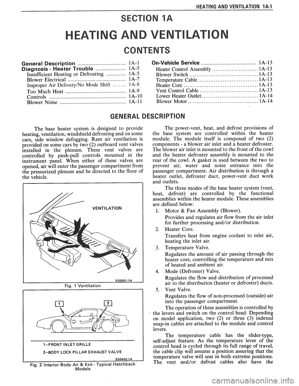
provided on some cars by two (2) outboard vent valves
installed in the plenum. These vent valves are
controlled by push-pull controls mounted in the
instrument panel. When either of these valves are
opened, air will enter the passenger compartment from
the pressurized plenum and be directed to the floor of
the vehicle.
/& VENTILATION
1-FRONT INLET GRILLE
2-BODY LOCK PILLAR EXHAUST VALVE
Fig. 2 Interior Body Air & Exit - Typical Hatchback Models
The power-vent, heat, and defrost provisions of
the base system are controlled within the heater
module. The module itself is composed of two (2)
components
- a blower air inlet and a heater defroster.
The blower air inlet is mounted to the front of the cowl
and the heater defroster assembly is mounted to the
rear of the cowl. A gasket is used between the two to
prevent air, water and noise entrance into the
passenger compartment. Air distribution is through a
heater outlet, defroster duct, power-vent duct work
and outlets.
The three modes of the base heater system (vent,
heat, defrost) are controlled by the functional
assemblies within the heater module. These assemblies
are defined below:
1. Motor & Fan Assembly (Blower).
Provides and regulates air flow from the air inlet
for further processing and/or distribution.
2. Heater Core.
Transfers heat from engine coolant to inlet air,
heating the inlet air.
3. Temperature Valve.
Regulates the amount of air passing through the
heater core, controlling the temperature and mix
of heated and ambient air.
4. Mode (Defroster) Valve.
Regulates the flow and distribution of processed
air to the distribution (heater or defroster) ducts.
5. Vent Valve.
Regulates the flow of non-processed (outside) air
into the passenger compartment.
The operation of these assemblies is controlled by
the levers and switch on the control head. Depending
on model application, two (2) or three
(3) indexed
snap-in cables are attached to the module and control
levers.
The temperature cable has the slider-type,
self-adjust feature. As the temperature lever of the
control head is cycled through its full range of travel,
the cable clip will assume a position assuring that the
temperature valve will seat in both extreme positions.
The vent and/or defrost cables also have the
Page 25 of 1825
1A-2 HEATING AND VENTILATION
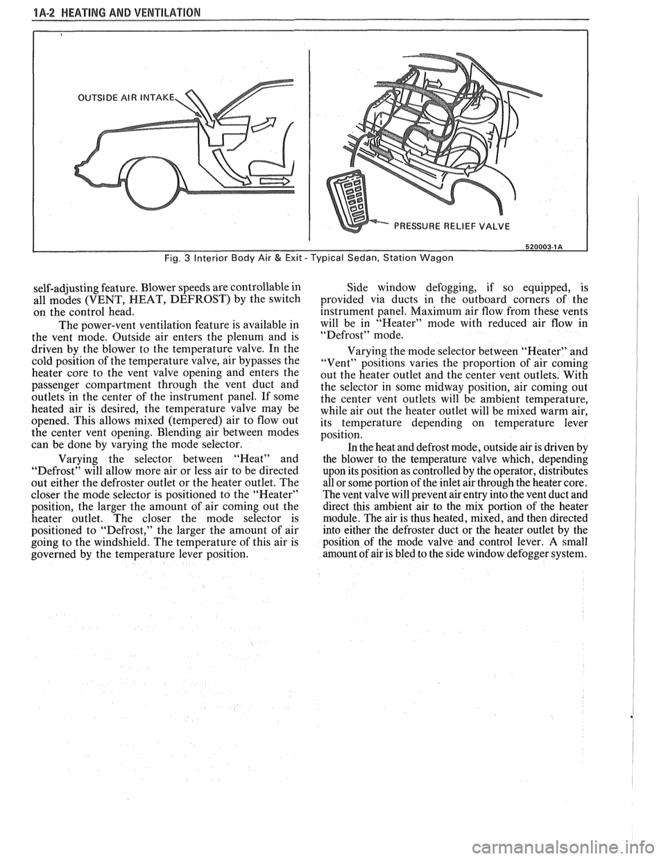
520003-1 A
Fig. 3 Interior Body Air & Exit - Typical Sedan, Station Wagon
self-adjusting feature. Blower speeds are controllable in
all modes (VENT, HEAT, DEFROST) by the switch
on the control head.
The power-vent ventilation feature is available in
the vent mode. Outside air enters the plenum and is
driven by the blower to the temperature valve. In the
cold position of the temperature valve, air bypasses the
heater core to the vent valve opening and enters the
passenger compartment through the vent duct and
outlets
in the center of the instrument panel. If some
heated air is desired, the temperature valve may be
opened. This allows mixed (tempered) air to flow out
the center vent opening. Blending air between modes
can be done by varying the mode selector.
Varying the selector between "Heat" and
"Defrost" will allow more air or less air to be directed
out either the defroster outlet or the heater outlet. The
closer the mode selector is positioned to the "Heater"
position, the larger the amount of air coming out the
heater outlet. The closer the mode selector is
positioned to "Defrost," the larger the amount of air
going to the windshield. The temperature of this air is
governed by the temperature lever position. Side window
defogging, if so equipped, is
provided via ducts in the outboard corners of the
instrument panel. Maximum air flow from these vents
will be in "Heater" mode with reduced air flow in
"Defrost" mode.
Varying the mode selector between "Heater" and
"Vent" positions varies the proportion of air coming
out the heater outlet and the center vent outlets. With
the selector in some midway position, air coming out
the center vent outlets will be ambient temperature,
while air out the heater outlet will be mixed warm air,
its temperature depending on temperature lever
position.
In the heat and defrost mode, outside air is driven by
the blower to the temperature valve which, depending
upon its position as controlled by the operator, distributes
all or some portion of the inlet air through the heater core.
The vent valve will prevent air entry into the vent duct and
direct this ambient air to the mix portion of the heater
module. The air is thus heated, mixed, and then directed
into either the defroster duct or the heater outlet by the
position of the mode valve and control lever.
A small
amount of air is bled to the side window defogger system.
Page 26 of 1825
HEAPING AND VENTILA"T0N 1A-3
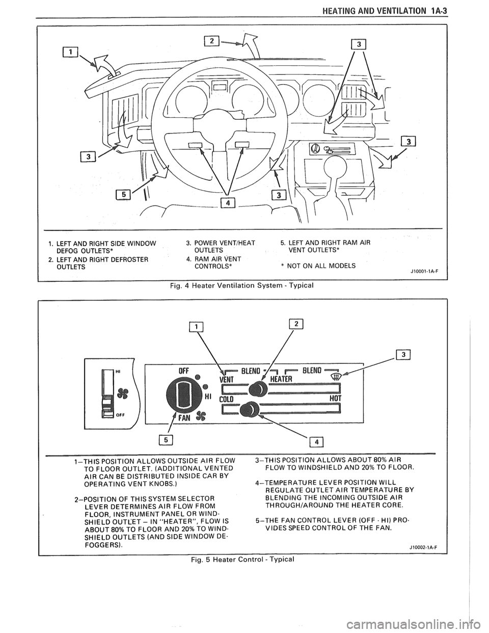
1, LEFT AND RIGHT SIDE WINDOW 3. POWER VENTIHEAT 5. LEFT AND RIGHT RAM AIR
DEFOG OUTLETS* OUTLETS VENT OUTLETS*
2. LEFT AND RIGHT DEFROSTER 4. RAM AIR VENT
OUTLETS CONTROLS* * NOT ON ALL MODELS J10001-1A-F
Fig. 4 Heater Ventilation System - Typical
1-THIS POSITION ALLOWS OUTSIDE AIR FLOW 3-THIS
POSITION ALLOWS ABOUT 80% AIR
TO FLOOR OUTLET. (ADDITIONAL VENTED FLOW
TO WINDSHIELD AND 20% TO FLOOR.
AIR CAN BE DISTRIBUTED INSIDE CAR BY
OPERATING VENT KNOBS.) 4-TEMPERATURE
LEVER POSITION WILL
REGULATE OUTLET AIR TEMPERATURE BY
2-POSITION OF
THIS SYSTEM SELECTOR BLENDING
THE INCOMING OUTSIDE AIR
LEVER DETERMINES AIR FLOW FROM THROUGHIAROUND THE HEATER CORE.
FLOOR, INSTRUMENT PANEL OR WIND-
SHIELD OUTLET - IN "HEATER", FLOW IS 5-THE
FAN CONTROL LEVER (OFF - HI) PRO.
ABOUT
80% TO FLOOR AND 20% TO WIND- VIBES SPEED CONTROL OF THE FAN.
SHIELD OUTLETS (AND
SlDE WINDOW DE-
FOGGERS).
Fig. 5 Heater Control - Typical
Page 49 of 1825
1B-6 AIR CONDlTlONlNC
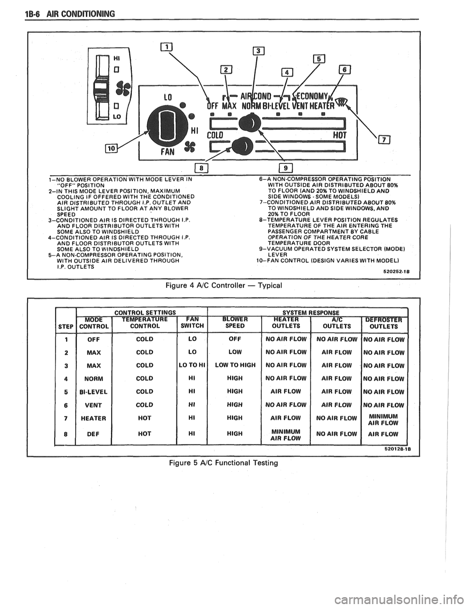
"OFF" POSITION WITH OUTSIDE AIR DISTRIBUTED ABOUT 80%
2-IN THIS MODE LEVER POSITION, MAXIMUM TO
FLOOR (AND 20% TO WINDSHIELD AND
COOLING IF OFFERED WITH THE CONDITIONED SIDE WINDOWS -SOME MODELS)
AIR DISTRIBUTED THROUGH I.P. OUTLET AND 7-CONDITIONED
AIR DISTRIBUTED ABOUT 80% SLIGHT AMOUNT TO FLOOR AT ANY BLOWER TO
WINDSHIELD AND SIDE WINDOWS, AND
20% TO FLOOR
3-CONDITIONED AIR IS DIRECTED THROUGH
I.P. 8-TEMPERATURE LEVER POSITION REGULATES
AND FLOOR DISTRIBUTOR OUTLETS WITH TEMPERATURE OF THE AIR ENTERING THE
SOME ALSO TO WINDSHIELD PASSENGER
COMPARTMENT BY CABLE
4-CONDITIONED AIR IS DIRECTED THROUGH
I.P. OPERATION OF THE HEATER CORE
AND FLOOR DISTRIBUTOR OUTLETS WITH TEMPERATURE DOOR
SOME ALSO TO WINDSHIELD 9-VACUUM
OPERATED SYSTEM SELECTOR (MODE)
5-A NON-COMPRESSOR OPERATING POSITION, LEVER
WITH OUTSIDE AIR DELIVERED THROUGH 10-FAN CONTROL
(DESIGN VARIES WITH MODEL) I.P. OUTLETS
Figure 4 AIC Controller -- Typical
Figure 5 A/C Functional Testing
Page 152 of 1825
STEERING WHEELS AND COLUMNS 385.1
SECTION 3B5
STEER NG WHEELS AND COLUMNS
NOTICE: All steering wheel and column fasteners are important attaching parts in that they could affect
the performance of vital parts and systems, and/or could result in major repair expense. They
must be replaced
with one of the same part number or with an equivalent part if
replacement becomes necessary. Do not use a
replacement part of lesser quality or substitute design. 'Torque values must be used as specified during reassembly
to assure proper retention of all parts. There is to be no welding as
it may result in extensive damage and weakening
of the metal.
For prevailing torque
nut(s) and bolts(s), refer to the "Reuse of Prevailing Torque Nut(<) and Bolt(s) " chart
in Section OA.
CONTENTS
..................... ................................................................... GENERAL DESCRIPTION .. 3B5-1 ............................................. ........................ MAINTENANCE AND ADJUSTMENTS .. 3B5-1 ON-CAR SERVICE ........................................................................................................ 3B5-2
Steering Column ............................................................................................................ 3B5-2 ......................................................................................................... Intermediateshaft 3B5-3
Park Lock Cable .................................................................... 3B54 ......................................................................................... Checking For Accident Damage 3B5-5 ............................................................................ Unit Repair Intermediate Shaft Assembly 3B5-6
..................................................................................... Standard Column @lanual Trans) 3B5-7 ......................................................... ....................... Standard Column (Auto Trans) .. 3B5-13 Tilt Column (Manual Trans) ............................................................................................. 3B5-19
Tilt Column (Auto Trans). ................................................................................................ 3B5-27
................ .................... TORQUE SPECIFICATIONS .. .. 3B5-35
SPECIAL TOOLS .......................................................................................................... 3B5-35
GENERAL DESCRIPTION
STEERING COLUMN
The function locking energy absorbing steering
column includes three important features in addition
to the steering function:
1. 'The column is energy absorbing, designed to
compress in a front-end collision to minimize the
possibility of an injury to the driver of the car.
2. The ignition switch and lock are mounted
conveniently on this column.
3. With the column mounted lock, the ignition and
steering operations can be locked to inhibit theft
of the car.
The turn signal lever provides for control of
headlight beams, windshield washer and wipers.
The column may be easily
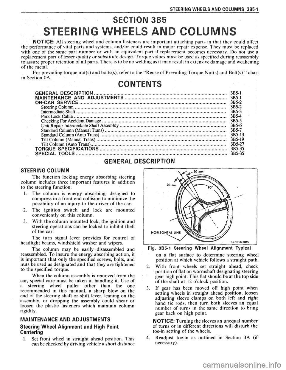
disassembled and Fig. 385-1 Steering Wheel Alignment ~ypical
reassembled. To insure the energy absorbing action, it
on a flat surface to determine steering wheel
is important that only the specified screws, bolts, and
position at which vehicle follows a straight path.
nuts be used as designated and that they are tightened
2. With front wheels set straight ahead, check to the specified torque.
position of flat on wormshaft designating steering
When the column assembly is removed from the
gear high point. This flat should be at the top side
car, special care must be taken in handling it. Use of
of the shaft at 12 o'clock position.
a steering puller other than the One 3, if gear has been moved off high when recommended in this manual, a sharp blow on the
setting wheels in straight ahead position, loosen
end of the steering shaft or shift lever, leaning on the
assembly, or dropping the assembly could shear or adjusting
sleeve clamps on both left and right
hand tie rods, then turn both sleeves an equal
loosen the plastic fasteners which maintain column
rigidity. number
of turns in the same direction
to bring
gear back
on high point.
MAINTENANCE AND ADJUSTMENTS NOTICE: Turning the sleeves an unequal number
Steering Wheel Alignment and High Point of turns or in different directions will disturb the
Centering toe-in setting of the wheels.
1. Set front wheel in straight ahead position, This 3. Readjust toe-in as outlined in Section 3A (if
can be checked by driving vehicle
a short distance necessary).