1988 PONTIAC FIERO window
[x] Cancel search: windowPage 65 of 1825
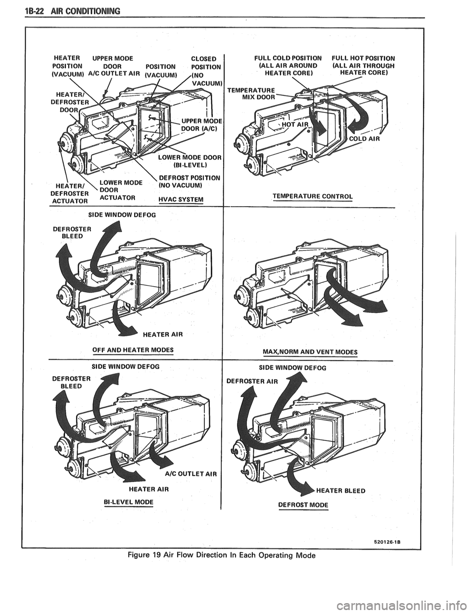
1B-22 AIR CONDITIONING
HEATER UPPER MODE CLOSED
POSITION DOOR POSITION POSITION
I SIDE WINDOW DEFOG
DEFROSTER
A BLEED
HEATER AIR
OFF AND HEATER MODES
SlDE WINDOW DEFOG
HEATER AIR
BI-LEVEL MODE FULL
COLD POSITION
FULL HOT POSITION
(ALL AIR AROUND
(ALL AIR THROUGH
HEATER CORE) HEATER CORE)
TEMPERATURE
TEMPERATURE
COlUTROL
MAX,NORM AND VENT MODES
SlDE WINDOW DEFOG
DEFROSTER AIR
HEATER BLEED
DEFROST MODE
5201 26-1 8
Figure 19 Air Flow Direction In Each Operating Mode
Page 295 of 1825
5-2 BRAKES
GENERAL DESCRIPTION
COMPOSIE EASTER CYLINDER
This vehicle uses a composite master cylinder which has
an aluminum body and a clear nylon reservoir with fluid
level indicators. The master cylinder uses a "quick take-up" feature in the
rear chamber to reduce pedal travel which may result from
increased fluid displacement required to move the caliper
piston. The quick take-up master cylinder includes a spring
loaded ball check valve which holds pressure in the
large-
diameter rear chamber. When the brake is first applied, the
movement of the rear piston causes fluid to be displaced
forward, past the primary piston primary seal and into the
primary high pressure chamber, which feeds the front
brakes. At a predetermined pressure, 480-690
kPa (70-100
mi), the ball unseats and fluid from the largi! rear bore is
disblaced past the ball and into the reservoir. The primary
and secondary high pressure chambers supply pressure to
the front and rear brakes, respectively, in the usual way.
When the pedal is released, the large-bore chamber is filled
with fluid by drawing fluid from the reservoir around the
quick take-up lip seal, and also through a small orifice in the
ball seat.
BRAKE FLUID LEVEL INDICATOR
(Figure 1)
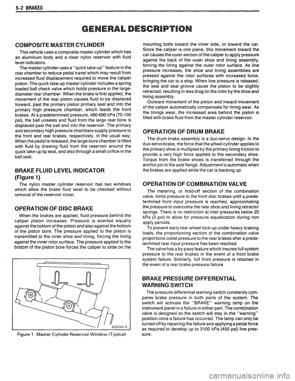
The nylon master cylinder reservoir has two windows
which allow the brake fluid level to be checked without
removal of the reservoir cover.
OPERATION OF DISC BRAKE
When the brakes are applied, fluid pressure behind the
caliper piston increases. Pressure is exerted equally
against the bottom of the piston and also against the bottom
of the piston bore. The pressure applied to the piston is
transmitted to the inner shoe and lining, forcing the lining
against the inner rotor surface. The pressure applied to the
bottom of the piston bore forces the caliper to slide on the
Figure
1 Master Cylinder Reservoir Window (Typical) mounting bolts toward the inner side,
or toward the car.
Since the caliper is one piece, this movement toward the
car causes the outer section of the caliper to apply pressure
against the back of the outer shoe and lining assembly,
forcing the lining against the outer rotor surface. As line
pressure increases, the shoe and lining assemblies are
pressed against the rotor surfaces with increased force,
bringing the car to a stop. When line pressure is released,
the seal and seal groove cause the piston to be slightly
retracted, resulting in less drag on the rotor by the shoe and
lining assembly.
Outward movement of the piston and inward movement
of the caliper automatically compensate for lining wear. As
the linings wear, the increased area behind the piston is
filled with brake fluid from the master cylinder reservoir.
OPERATION OF DRUM BRAKE
The drum brake assembly is a duo-servo design. In the
duo-servo brake, the force that the wheel cylinder applies to
the primary shoe is
multipled by the primary lining friction to
provide a very high force applied to the secondary shoe.
Torque from the brake shoes is transferred through the anchor pin to the axle flange. Adjustment is automatic when
the brakes are applied while the car is backing up.
OPERATION OF COMBINATION VALVE
The metering, or hold-off section of the combination
valve, limits pressure to the front disc brakes until a prede-
termined front input pressure is reached, approximating
the pressure to overcome the rear shoe and lining retractor
springs. There is no restriction at inlet pressures below 20
kPa (3 psi) to allow for pressure equalization during non
apply periods.
To prevent early rear wheel lock-up under heavy braking
loads, the proportioning section of the combination valve
proportions outlet pressure to the rear brakes after a prede-
termined rear input pressure has been reached.
The valve has a by-pass feature which insures full system
pressure to the rear brakes in the event of a front brake
system failure. Similarly, full front pressure is retained in
the event of a rear brake pressure failure.
BRAKE PRESSURE DIFFERENTIAL
WARNING
SWITCH
The pressure differential warning switch constantly com-
pares brake pressure in both parts of the system. The
switch will activate the "BRAKE" warning lamp on the
instrument panel in a failure in either part. The combination
valve is designed so the switch will stay in the "warning"
position once a failure has occurred. The lamp can only be
turned off by repairing the failure and applying a pedal force
as required to develop up to 3100
kPa (450 psi) line pres-
sure.
Page 529 of 1825
6EZ-A-38 5.OL (VIN E) DRIVEABILITY AND EMISSIONS
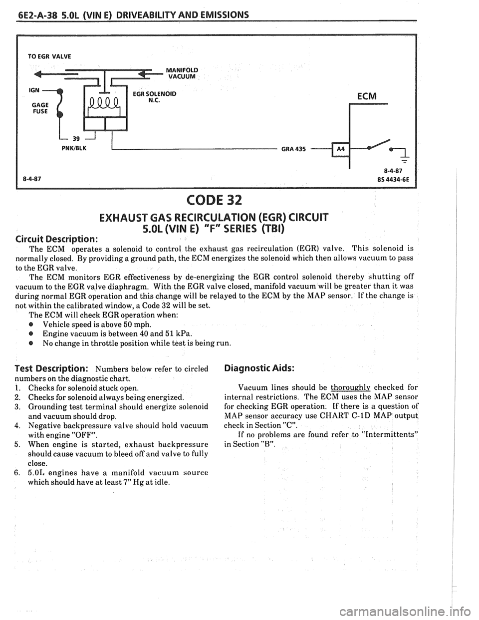
TO EGR VALVE
CODE 32
EXHAUSWAS RECIRCULATION (EGR) CIRCUIT
5.OL (VIN E) "FF" SERIES (TBI)
Circuit Description:
The ECM operates a solenoid to
control the exhaust gas recirculation (EGR) valve. This solenoid is
normally closed. By providing a ground path, the ECM energizes the solenoid which then allows vacuum to pass
to the EGR valve.
The ECM monitors EGR effectiveness by de-energizing the EGR control solenoid thereby shutting off
vacuum to the EGR valve diaphragm. With the EGR valve closed, manifold vacuum will be greater than it was
during normal EGR operation and this change will be relayed to the ECM by the MAP sensor. If the change is
not within the calibrated window, a Code
32 will be set.
The ECM will check EGR operation when:
@ Vehicle speed is above 50 mph.
@ Engine vacuum is between 40 and 51 kPa.
@ No change in throttle position while test is being run.
Test Description: Numbers below refer to circled
numbers on the diagnostic chart.
1. Checks for solenoid stuck open.
2. Checks for solenoid always being energized.
3. Grounding test terminal should energize solenoid
and vacuum should drop.
4. Negative backpressure valve should hold vacuum
with engine "OFF".
5. When engine is started, exhaust backpressure
should cause vacuum to bleed off and valve to fully
close.
6. 5.OL engines have a ~nanifold vacuum source
which should have at least
7" Hg at idle.
Diagnostic Aids:
Vacuum lines should be thoroughly checked for
internal restrictions. The ECM uses the MAP sensor
for checking EGR operation. If there is a question of
MAP sensor accuracy use
CHART C-1D MAP output
check in Section "C".
If no problems are found refer to "Intermittents"
in Section
"13".
Page 1166 of 1825
CONTENTS
ELECTRICAL DIAGNOSIS
Cell
1
2
3
4 5
10
11
12 14
20
21
22
23
30
31
33
34
40
4
1
60
61
62
63
64
65
66
67
68
Index
Introduction
Symbols
Troubleshooting Procedures Repair Procedures
Power Distribution
Fuse Block Details
Light Switch Details
Ground Distribution
Engine:
V6 VIN S
Engine: V8 VIN
F
Engine: V8 VIN E
Engine:
V8 VIN 8
Starter and Charging System
Coolant Fans
Vehicle Speed Sensor
Cruise Control Horns
Brake Warning System
Heater
Defogger
Air Conditioning: System Check
Air Conditioning: Blower Controls
Air Conditioning: Compressor Controls
Air Conditioning: Air Delivery
Air Conditioning: Blower Controls
Air Conditioning: Compressor Controls
Air Conditioning: Air Delivery Cell
77
8
1
82
86 90
9
1
100
102
103
110
111
112
114
117
120
130
133
134
135
141
143
145
150
151
201 202
203
Warnings and Alarms: Chime
Instrument Panel: Gages Cluster
Instrument Panel:
Digital Cluster
Driver Information Center
(DIC)
WiperlWasher
WiperlWasher: Pulse
Headlights
Headlight Doors
Headlights with Lamp Monitor
Exterior Lights
Exterior Lights with Lamp Monitor
Back Up Lights
Interior Lights
Interior Lights Dimming
Power Windows
Power Door Locks
Theft Deterrent
Hatch Release
Hatch Pull-Down
Power Mirrors
Automatic Day-Night Mirror
Lumbar Support
Radio Power Antenna
Component Location Views
Harness Connector Faces
Harness Routing Views
Page 1168 of 1825
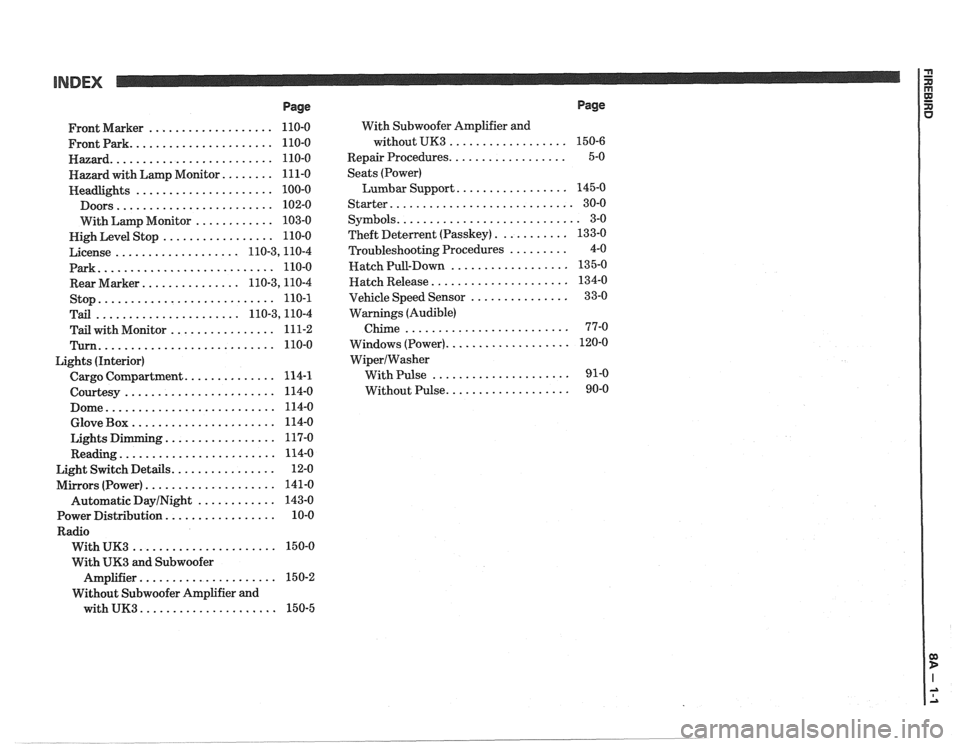
INDEX
Page
................... Front Marker 110-0
...................... Frontpark 110-0
......................... Hazard 110-0
........ Hazard with Lamp Monitor 111-0
..................... Headlights 100-0
........................ Doors 102-0
............ With Lamp Monitor 103-0
................. Nigh Level Stop 110-0
................... License 110.3,11 0.4
Park
........................... 110-0
............... Rear Marker 110.3,11 0.4
stop
........................... 110-1
...................... Tail 110.3,11 0.4
................ Tail with Monitor 111-2
Turn ........................... 110-0
Lights (Interior)
.............. Cargo Compartment 114-1
....................... Courtesy 114-0
.......................... Dome 114-0
...................... Glove Box 114-0
................. Lights Dimming 117-0
........................ Reading 114-0
................ Light Switch Details 12-0
.................... Mirrors (Power) 141-0
Automatic
DayINight ............ 143-0
................. Power Distribution 10-0
Radio
...................... With UK3 150-0
With
UK3 and Subwoofer
..................... Amplifier 15 0-2
Without Subwoofer Amplifier and
with
UK3 ..................... 150-5 With
Subwoofer Amplifier and
without UK3
..................
.................. Repair Procedures
Seats (Power)
Lumbar Support
.................
Starter ............................
........................... Symbols
........... Theft Deterlent (Passkey)
......... Troubleshooting Procedures
.................. Hatch Pull-Down
..................... Hatch Release
............... Vehicle Speed Sensor
Warnings (Audible)
Chime
.........................
................... Windows (Power)
WiperIWasher
With Pulse .....................
................... Without Pulse
Page
Page 1217 of 1825
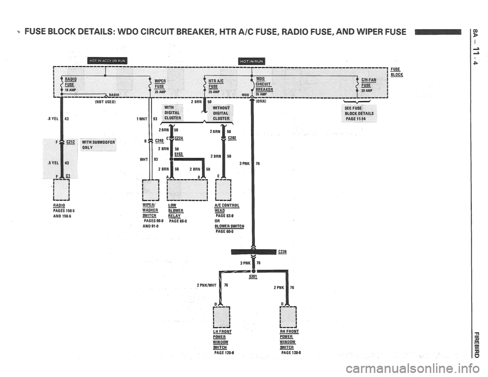
FUSE BLOCK DETAILS: WDO ClRGUlT BREAKER, HTR A16 FUSE, RADlO FUSE, AND WIPER FUSE
RADIO - PAGES 150-5 AND 150.6
WIPER1 LOW A/C CONTROL
WASHER BLOWER HEAD - SWlTCH PAGE 63-0 PAGES 90-0 PAGE 664 OR
AND 91-0 BLOWER SWITCH
PAGE 600
3 PNK 76
LH FRONT RH FRONT
POWER
- POWER WINDOW WINDOW
PAGE
120-0 PAGE 120-0
Page 1342 of 1825
DEFOGGER
TROUBLESHOOTING HINTS
e Try the following checks before doing the
System Check.
1. Check the PWR ACC Circuit Breaker by
operating the Power Door Locks or Power
Seats (if equipped).
2. Check the Gages Fuse by observing that the
Instrument Cluster Lights.
3. Check ground 6200 by observing that the
Cigar Lighter operates normally.
4. Check that the connectors on the Defogger
and the Defogger Timer-Relay are properly
mated.
5. If one or more of the grid lines do not heat,
refer to the Body Service Manual (Section
2) for repair procedures.
e Go to System Check for a guide to normal
operation.
a Go to System Diagnosis for diagnostic tests.
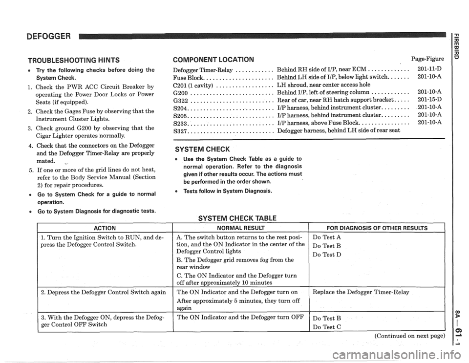
COMPONENT LOCATION Page-Figure
............ ............. Defogger Timer-Relay Behind
RH side of IIP, near ECM 201-1 1-D
..................... Fuse Block. Behind LH side
of I/P, below light switch. ...... 201-10-A
.................. 6201 (1 cavity) LH
shroud, near center access hole
.......................... 6200 Behind IIP, left of steering column ............ 201-10-16
.......................... 6322 Rear of car, near RH hatch support bracket. .... 201-15-D
.......................... S204. IIP harness, behind instrument cluster. ........ 201-10-A
.......................... S205. IIP harness, behind instrument cluster. ........ 201-10-A
.......................... S233. IIP harness, above Fuse Block. ............... 201-10-A
.......................... S327. Defogger harness, behind LR side of rear seat
SYSTEM CHECK
e Use the System Check Table as a guide to
normal operation. Refer to the diagnosis
given if other results occur. The actions must
be
pedormed in the order shown.
Tests follow in System Diagnosis.
SYSTEM CHECK TABLE -- -
ACTION NORMAL RESULT FOR DIAGNOSIS OF OTHER RESULTS
1. Turn the Ignition Switch to RUN, and de-
press the Defogger Control Switch.
2. Depress the Defogger Control Switch again
3. With the Defogger ON, depress the Defog-
ger Control OFF Switch
I
A. The switch button returns to the rest posi-
tion, and the ON Indicator in the center of the
Defogger Control lights
B. The Defogger grid removes fog from the
rear window
C. The ON Indicator and the Defogger turn
off after approximately
10 minutes
The ON Indicator and the Defogger turn on
After approximately
5 minutes, they turn off
again
The ON Indicator and the Defogger turn OFF Do
Test A
Do Test B
Do Test D
Replace the Defogger Timer-Relay
Do Test B
(Continued on next page)
Page 1344 of 1825
DEFOGGER
r If all the voltages are correct, and the
Defogger still does not operate properly,
do Test D.
1. Check the PNK/BLK (39) wire for an
open (see schematic). If the wire is OK,
check the Gages Fuse.
2. Replace the Defogger Control.
3. Check the PPL/WHT (293) wire for an
open (see schematic). If the wire is OK,
do Test B.
4. Check the INST LP Fuse. Check the
GRY
(8) wire for an open (see
schematic).
5. Check the BLK (150) wire for an open
(see schematic). Check that ground
6200 is clean and tight. Replace Panel
Light if wire and ground are OK.
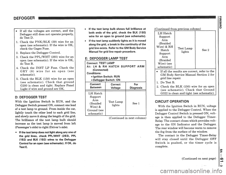
D: DEFOGGER TEST
With the Ignition Switch in RUN, and the
Defogger Switch pressed
ON, connect one lead
of a test lamp to ground. From inside the car,
lightly touch the other lead to each grid line,
and slowly move it along the length of the grid.
The brilliance of the test lamp bulb should
increase as the test lamp is moved from left
(Passenger's side) to right (Driver's side).
0 If the test lamp does not light along any one of
the grid lines, check
PPLIWHT (2931, PPL
(192) and BLK (192) wires to the Defogger
Control for an open
(see schematic). If OK, do
Test
E.
If the test lamp bulb shows full brilliance at
both ends of the grid, check the BLK
(1 50)
wire for an open to ground (see schematic).
e If the test lamp suddenly lights as it is moved
along the grid, a break in the continuity of the
grid line exists. Refer to the
GM Body Service
Manual for grid line repair procedure.
E: DEFOGGER LAMP TEST
CH SUPPORT ARM
Ignition Switch: RUN
LH Hatch
Support Arm
(Braided Test
Lamp
lights See
1
Wire) &
Ground
(see
schematic)
(Continued in next column) (Continued
from previous column)
See 2
Arm
(Braided
Wire) (see
schematic)
I
If all the results are correct, refer to the
GM Body Service Manual Section 2 for
grid line repair.
1. Do Test B.
2. Check the BLK (150) wire for an open
(see schematic). Check that Ground
6322 is clean and tight (see schematic).
CIRCUIT OPERATION
With the Ignition Switch in RUN, voltage
is applied to the Defogger Control. When the
Defogger Control Switch is pressed ON, volt-
age is then applied to the Defogger
Timer-
Relay. The contact closes which provides volt-
age to the ON Indicator and the Defogger.
The rear window will become warm to remove
the fog from the surface of the window.
The contact in the Defogger Timer-Relay
will stay closed until the Defogger OFF
Switch is pushed, or the timer cycle is
complete.
(Continued on next page)