1988 PONTIAC FIERO window
[x] Cancel search: windowPage 1719 of 1825
5W-8 BOORS - F STYLE
3. With weatherstrip removed, screws securing
weatherstrip retainer to side roof rail are exposed.
Mark position of retainer on rail or pillar and
remove screws from retainer.
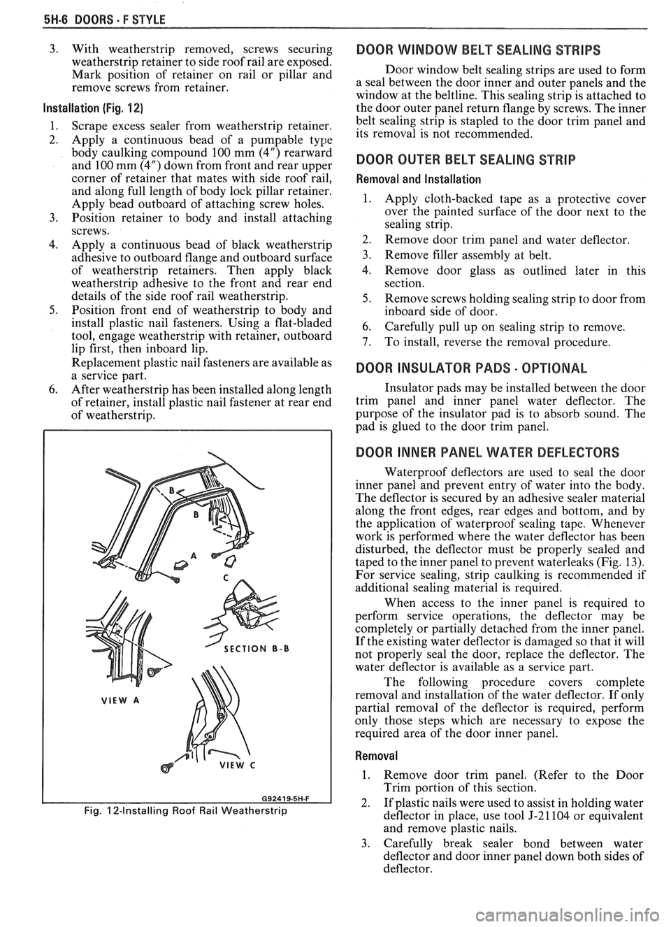
Installation (Fig. 1 2)
1.
Scrape excess sealer from weatherstrip retainer.
2. Apply a continuous bead of a
pumpable type
body caulking compound 100 mm (4") rearward
and 100 mm (4") down from front and rear upper
corner of retainer that mates with side roof rail,
and along full length of body lock pillar retainer.
Apply bead outboard of attaching screw holes.
3. Position retainer to body and install attaching
screws.
4. Apply a continuous bead of black weatherstrip
adhesive to outboard flange and outboard surface
of weatherstrip retainers. Then apply black
weatherstrip adhesive to the front and rear end
details of the side roof rail weatherstrip.
5. Position front end of weatherstrip to body and
install plastic nail fasteners. Using a flat-bladed
tool, engage weatherstrip with retainer, outboard
lip first, then inboard lip.
Replacement plastic nail fasteners are available as
a service part.
6. After weatherstrip has been installed along length
of retainer, install plastic nail fastener at rear end
of weatherstrip.
SECTION B-B
Fig. 12-Installing Roof Rail Weatherstrip
DOOR WINDOW BELT SEALING STRIPS
Door window belt sealing strips are used to form
a seal between the door inner and outer panels and the
window at the beltline. This sealing strip is attached to
the door outer panel return flange by screws. The inner
belt sealing strip is stapled to the door trim panel and
its removal is not recommended.
DOOR OUER BELT SEALING STRIP
Removal and Installation
1.
Apply cloth-backed tape as a protective cover
over the painted surface of the door next to the
sealing strip.
2. Remove door trim panel and water deflector.
3. Remove filler assembly at belt.
4. Remove door glass as outlined later in this
section.
5. Remove screws holding sealing strip to door from
inboard side of door.
6. Carefully pull up on sealing strip to remove.
7. To install, reverse the removal procedure.
DOOR INSULAWR PADS - OPTIONAL
Insulator pads may be installed between the door
trim panel and inner panel water deflector. The
purpose of the insulator pad is to absorb sound. The
pad is glued to the door trim panel.
DOOR INNER PANEL WATER DEFLECTORS
Waterproof deflectors are used to seal the door
inner panel and prevent entry of water into the body.
The deflector is secured by an adhesive sealer material
along the front edges, rear edges and bottom, and by
the application of waterproof sealing tape. Whenever
work is performed where the water deflector has been
disturbed, the deflector must be properly sealed and
taped to the inner panel to prevent waterleaks (Fig. 13).
For service sealing, strip caulking is recommended if
additional sealing material
is required.
When access to the inner panel is required to
perform service operations, the deflector may be
completely or partially detached from the inner panel.
If the existing water deflector is damaged so that it will
not properly seal the door, replace the deflector. The
water deflector is available as a service part.
The following procedure covers complete
removal and installation of the water deflector. If only
partial removal of the deflector is required, perform
only those steps which are necessary to expose the
required area of the door inner panel.
Removal
1. Remove door trim panel. (Refer to the Door
Trim portion of this section.
2. If plastic nails were used to assist in holding water
deflector in place, use tool J-21104 or equivalent
and remove plastic nails.
3. Carefully break sealer bond between water
deflector and door inner panel down both sides of
deflector.
Page 1723 of 1825
5W-10 DOORS - F STYLE
2. Position the replacement bolt-on hinge within
scribe marks on the hinge pillar facing and center
punch bolt hole locations in hinge pillar.
3. Using a 13 mm
(1/2") drill bit, drill hinge
attaching holes. The 13 mm
(1/2") holes in the
door hinge pillar will provide for some in and out
door adjustment when reinstalling the door
assembly.
4. Coat surface of hinge strap that mates with hinge
pillar with medium bodied sealer. Install hinge
using specified service bolts and service anchor
plates. Tighten hinge bolts to 20 to 28
N.m (14
to 20 ft-lb) torque.
5. Install door to body.
Whenever hinge straps have been replaced and
the door reinstalled, the door should not be closed
completely until a visual check is made to
determine if lock fork bolt will correctly engage
with striker.
6. Install door water deflector and door trim panel.
BODY SIDE HINGE STRAP
Removal
1. Remove door assembly from body.
2. Center punch and scribe location of lower hinge
strap on body hinge pillar.
3. Scribe location of hinge strap on body pillar (Fig.
19).
4. Remove one of the following trim items
depending on which hinge strap is being repaired.
s Left-hand lower hinge - remove the
left-hand shroud trim panel.
Right-hand lower hinge
- remove
right-hand shroud trim panel.
5. Remove noise control adhesive patch to gain
access to bolt which was installed from the
inboard side of the car.
6. Using 15 mm socket, remove bolt installed from
inboard side of body.
7. From outside of car, use 13 mm socket and
remove remaining bolt.
8. Remove hinge strap from body.
Installation
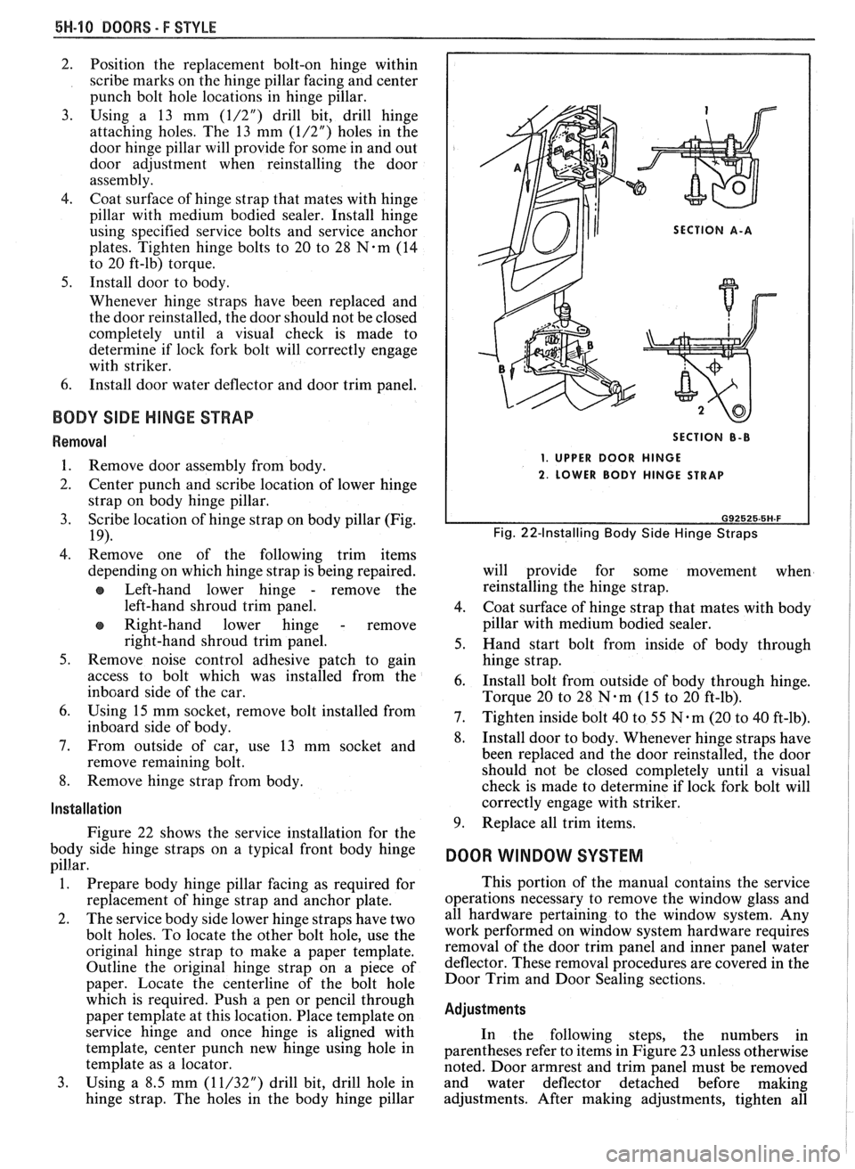
Figure 22 shows the service installation for the
body side hinge straps on a typical front body hinge
pillar.
1. Prepare body hinge pillar facing as required for
replacement of hinge strap and anchor plate.
2. The service body side lower hinge straps have two
bolt holes. To locate the other bolt hole, use the
original hinge strap to make a paper template.
Outline the original hinge strap on a piece of
paper. Locate the centerline of the bolt hole
which is required. Push a pen or pencil through
paper template at this location. Place template on
service hinge and once hinge is aligned with
template, center punch new hinge using hole in
template as a locator.
3. Using a 8.5 mm
(11/32") drill bit, drill hole in
hinge strap. The holes in the body hinge pillar
SECTION A-A
SECTION
B-B
1. UPPER DOOR HINGE
2. LOWER BODY HINGE STRAP
Fig. 22-Installing Body Side Hinge Straps
will provide for some movement when
reinstalling the hinge strap.
4. Coat surface of hinge strap that mates with body
pillar with medium bodied sealer.
5. Hand start bolt from inside of body through
hinge strap.
6. Install bolt from outside of body through hinge.
Torque 20 to 28
N.m (15 to 20 ft-lb).
7. Tighten inside bolt 40 to 55 N-m (20 to 40 ft-lb).
8. Install door to body. Whenever hinge straps have
been replaced and the door reinstalled, the door
should not be closed completely until a visual
check is made to determine if lock fork bolt will
correctly engage with striker.
9. Replace all trim items.
DOOR WINDOW SYSTEM
This portion of the manual contains the service
operations necessary to remove the window glass and
all hardware pertaining to the window system. Any
work performed on window system hardware requires
removal of the door trim panel and inner panel water
deflector. These removal procedures are covered in the
Door Trim and Door Sealing sections.
Adjustments
In the following steps, the numbers in
parentheses refer to items in Figure 23 unless otherwise
noted. Door armrest and trim panel must be removed
and water deflector detached before making
adjustments. After making adjustments, tighten all
Page 1724 of 1825
DOORS - F STYLE 5H-11
loosened attachments to 10 to 14 N-m (90 to 125 in-lb)
torque.
1. Window Rotated
- Loosen up-stops (2 and 6),
adjust inner panel cam (8) as required and tighten
attaching screws. Adjust up-stops as required and
tighten attaching screws.
2. Window
Upper Edge Inboard or Outboard
-
Loosen the following attachments.
a. Filler at belt (1 and 10)
b. Rear
guide upper support lower bolts (Fig.
3 1, item 5)
Adjust rear guide as needed and tighten bolts.
Adjust and tighten filler assembly.
3. Window Too Far Forward or Rearward
- Loosen
filler assembly bolts (3 and 10). With glass in
half-down position, loosen bolts on rear guide
channel (7). Position glass to opening as needed
and tighten bolts. Position filler to glass and
opening as needed and tighten bolts.
4. Window Too Nigh or Low in Up Position -
Adjust front and rear up-travel stops (2 and 6) as
required.
5. Window Binds
- Ease of window operation and
stability depend to a great extent on the glass
stabilizers (5) at the beltline. Contact should be
enough to stabilize glass but not restrict window
operation.
The door window assembly consists of a
frameless piece of solid tempered safety plate glass. The
glass is riveted to the window regulator sash. Figure 24
illustrates a typical door with the trim panel and water
deflector removed. This figure identifies the hardware
parts of the door.
Removal
1. Remove
door trim panel and inner panel water
deflector.
2. Raise window to half-up position.
3. Punch out center pins of glass to sash channel
attaching rivets.
4. Remove rear guide channel through rear access
hole.
5. Remove up stop.
6. Using a 6.3 mm
(1/4") drill bit, drill out
attaching rivets on sash channel (Fig. 25).
7. Raise
glass to remove from sash channel and
remove glass from door.
Installation
1. Remove drilled
out rivets and shavings from
door.
2. Check rivet bushings
and retainers on glass for
damage. If necessary, remove bushings using a
flat-bladed tool covered with cloth body tape.
Install by snapping rivet retainer into bushing.
3. Lower glass into door and position on sash
channel so holes in sash line up with holes in
bushings and retainers.
4. Using rivet tooi J-29022 or equivalent, install
1/4" peel
type rivet (part no. 20184399 or
equivalent) to retain glass to sash channel (Fig.
25).
5. Install rear guide channel. 6.
Install front up stop to support on inner panel.
7. Before installing trim parts, check window
operation for performance and fit to roof rail
weatherstrip.
8. Install all remaining parts.
WINDOW SASH CHANNEL
Removal and Installation
1.
Remove door trim panel and water deflector.
2. Remove door glass as outlined in the window
removal portion of this section.
3. Slide sash channel off regulator rollers and
remove channel from door through rear access
hole.
4. To install, reverse removal procedure.
WINDOW REGULATOR AND REGULATOR
MOTOR
Removal
1. Remove door trim panel and inner panel water
deflector.
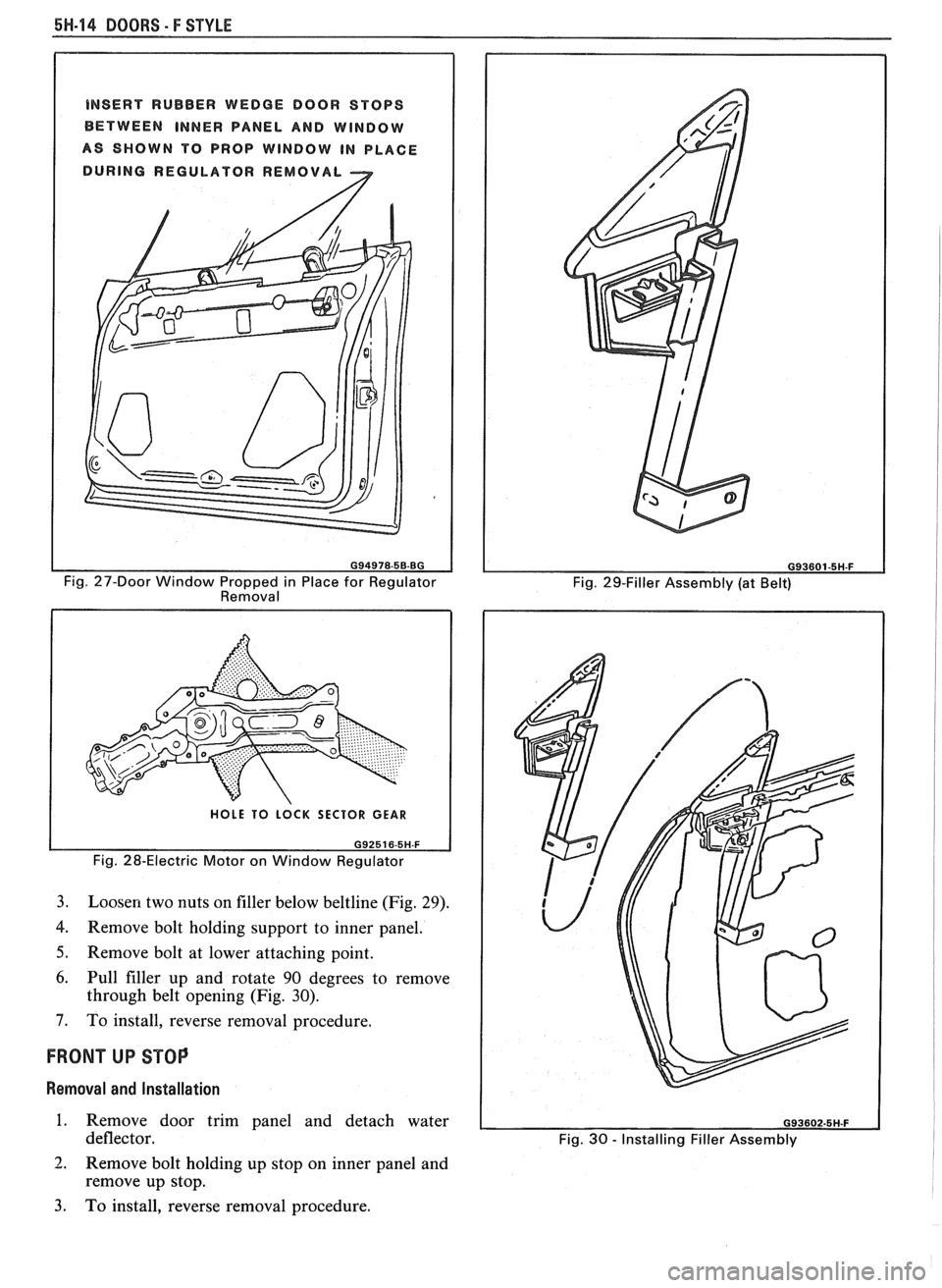
2. Raise window to half-up position and hold in
place by inserting rubber wedge door stops at
front and rear of window between window and
inner panel (Fig. 27).
3. Remove rear guide channel and inner panel cam
channel.
4. Punch out
center pins of regulator rivets; then
drill out rivets using 6.3 mm
(1/4") drill bit.
5. Move regulator rearward and disconnect wire
harness from motor (if present). Disengage roller
on regulator lift arm from glass sash channel.
6. Remove regulator through rear access hole.
CAUTION: If electric motor removal
from the regulator is required, the
sector gear
must be locked in position.
The regulator lift
arm is under tension
from the counterbalance spring and
could cause personal injury
if the
sector gear
is not locked in position.
7. Drill a
hole through the regulator sector gear and
backplate and install a bolt and nut to lock sector
gear in position (Fig. 28).
8. Using a 4.8 mm
(3/16") drill bit, drill out motor
attaching rivets and remove motor from
regulator.
Installation
1. To install motor to regulator, use rivet tool
J-29022 or equivalent, and install 4.8 mm
(3/16")
rivets or 4.8 mm (3/16") nuts and bolts. Remove
bolt and nut used to secure sector gear in position.
2. Place regulator through rear access hole into door
inner panel. If electric regulator is being installed,
connect wire connector to motor prior to
installing regulator to inner panel.
3. Locate lift arm roller into glass sash channel.
4. Using rivet tool J-29022 or equivalent, rivet
regulator to inner panel of door using
1/4"x0.
500" aluminum peel type rivets (part no. 9436175
Page 1726 of 1825
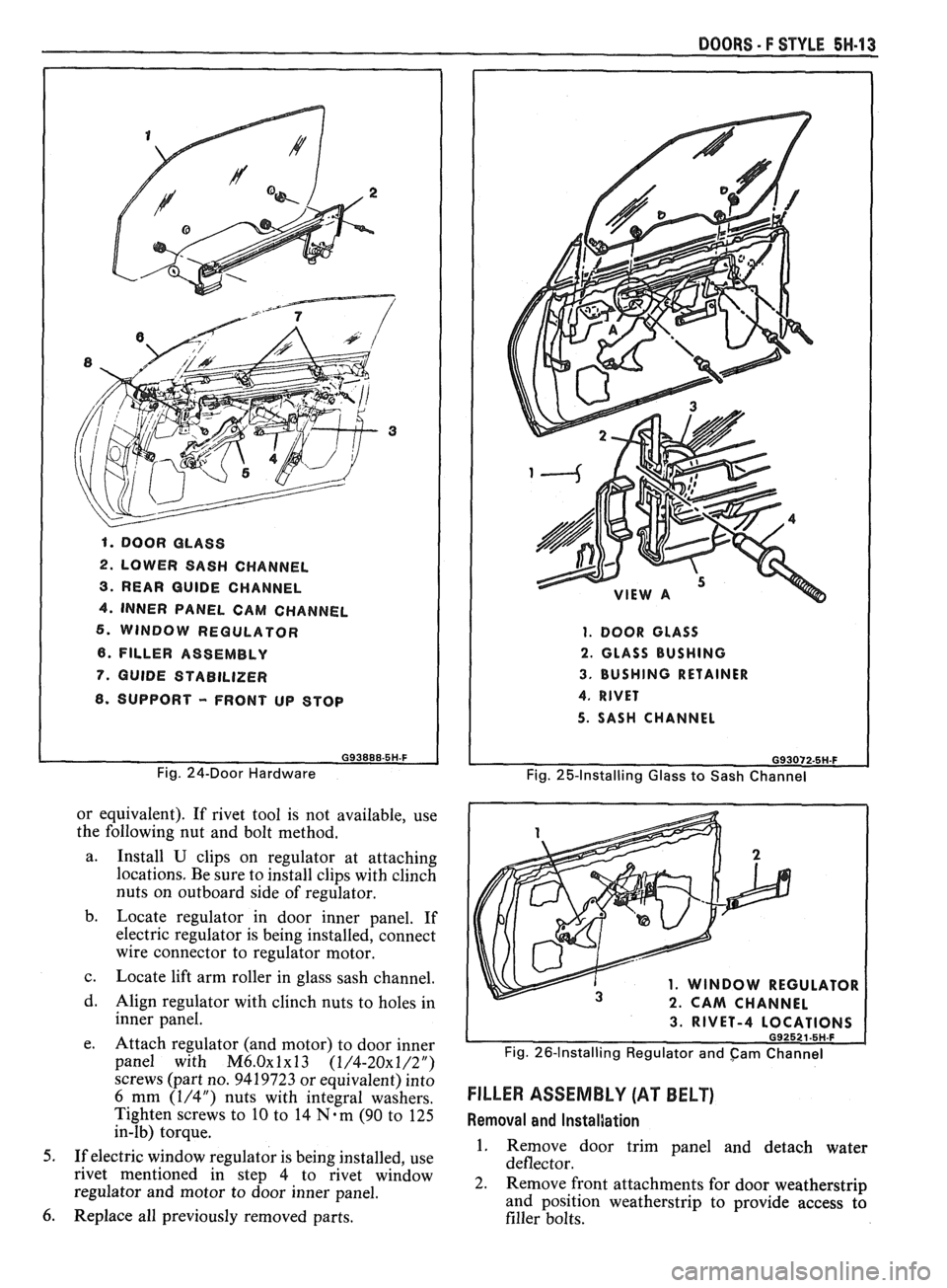
1. DOOR GLASS
2. LOWER SASH CHANNEL
3. REAR GUIDE CHANNEL
4. INNER PANEL CAM CHANNEL
6. WINDOW REGULATOR
6. FILLER ASSEMBLY
7. GUIDE STABILIZER
8. SUPPORT - FRONT UP STOP
G93888-5H-F
Fig. 24-Door Hardware
or equivalent). If rivet tool is not available, use
the following nut and bolt method.
a. Install
U clips on regulator at attaching
locations. Be sure to install clips with clinch
nuts on outboard side of regulator.
b. Locate regulator in door inner panel. If
electric regulator is being installed, connect
wire connector to regulator motor.
c. Locate lift arm roller in glass sash channel.
d. Align regulator with clinch nuts to holes in
inner panel.
e. Attach regulator (and motor) to door inner
panel with
M6.0~1~13 (1/4-20x1/2")
screws (part no. 9419723 or equivalent) into
6 mm (1/4") nuts with integral washers.
Tighten screws to
10 to 14 N-m (90 to 125
in-lb) torque.
5. If electric window regulator is being installed, use
rivet mentioned in step 4 to rivet window
regulator and motor to door inner panel.
6. Replace all previously removed parts.
DOORS - F STYLE 5H-13
1. DOOR GLASS
2. GLASS BUSHING
3. BUSHING RETAINER
4. RIVET
5. SASH CHANNEL
G93072-5H.F
Fig. 25-Installing Glass to Sash Channel
1. WINDOW REGULATOR
2. CAM CHANNEL
3. RIVET-4 L
Fig. 26-Installing Regulator and cam Channel
FILLER ASSEMBLY (AT BELT)
Removal and InstalJation
1. Remove door trim panel and detach water
deflector.
2. Remove front attachments for door weatherstrip
and position weatherstrip to provide access
tb
filler bolts.
Page 1727 of 1825
5H-14 DOORS - F STYLE
INSERT RUBBER WEDGE DOOR STOPS
BETWEEN
INNER PANEL AND WINDOW
AS SHOWN TO PROP WINDOW IN PLACE
DURING REGULATOR REMOVAL
2
Fig. 27-Door Window Propped in Place for Regulator
Removal
HOLE TO LOCK SECTOR GEAR
Fig. 28-Electric Motor on Window Regulator
3.
Loosen two nuts on filler below beltline (Fig. 29).
4. Remove bolt holding support to inner panel.
5. Remove bolt at lower attaching point.
6. Pull filler up and rotate 90 degrees to remove
through belt opening (Fig. 30).
7. To install, reverse removal procedure.
FRONT UP STOP
Removal and Installation
1. Remove door trim panel and detach water
deflector.
2. Remove bolt holding up stop on inner panel and
remove
up stop.
3. To install, reverse removal procedure.
Fig. 29-Filler Assembly (at Belt)
Fig.
30 - Installing Filler Assembly
Page 1729 of 1825
5H-16 DOORS. F STYLE
3; To install, reverse removal procedure. Tighten
nuts to 8
N-m (72 in-lb) torque.
Remote Mirror Face Replacement
CAUTION: To minimize the chance of
personal injury,
gloves and safety
glasses should be worn when
removing broken glass.
NOTICE: When breaking mirror, cover painted
surface of door to avoid damage.
1. To remove a scratched, broken, stained, etc.,
mirror face from the frame, tape, then break the
mirror glass and remove the broken glass and
fiber pad from the mirror frame.
2. Wipe inside of mirror frame clean.
3. To
install replacement mirror face, remove paper
backing from service mirror face and center
mirror in mirror frame. Press firmly to ensure
adhesion of the mirror face to the mirror frame.
POWER-OPERATED BIIXSIDE MIRRORS
Mirror Case and Motor Removal and Installation
Follow instructions which are included with new
service part. Use electrical tape to protect electrical
connections.
Mirror Housing Removal and Installation
1. From door trim panel side, remove remote
control mirror bezel, release and remove door
panel as described in Door Trim section and
disconnect wire harness connection from remote
mirror electrical switch.
2. Peel back water deflector enough to detach
harness from retaining tabs in door.
3. Remove mirror base-to-door stud nuts and lift
mirror housing and harness assembly from door.
4. To install, reverse removal procedure.
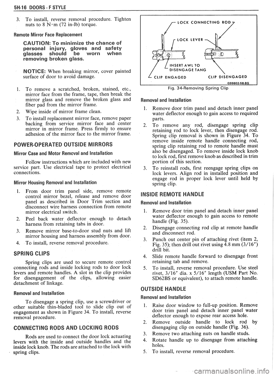
SPRING CLIPS
Spring clips are used to secure remote control
connecting rods and inside locking rods to door lock
levers and remote handles.
A slot in the clip provides
for disengagement of the clips, allowing easier
detachment of linkage.
Removal and lnstallation
To disengage a spring clip, use a screwdriver or
other suitable thin-bladed tool to slide clip out of
engagement as shown in Figure 34. To install, reverse
removal procedure.
CONNECTING RODS AND LOCKING RODS
Rods are used to connect the door lock actuating
levers with the inside and outside handles and the
inside lock knob. The rods are attached to the lock with
spring clips.
LOCK LEVER
( $&
DISENGAGE TANG / INSERT To
Fig. 34-Removing Spring Clip
Removal and Installation
1. Remove door trim panel and detach inner panel
water deflector enough to gain access to required
parts.
2. To remove any rod, disengage spring clip
retaining rod to lock lever, then disengage rod.
Spring clip removal is shown in Figure 34. To
remove inside remote handle connecting rod,
spring clip retaining rod to remote handle must
also be disengaged. To remove inside lock knob
to lock rod, first remove knob as described in trim
portion of this section.
3. To
reinstall rods, first reengage spring clips on
lock levers. Align rod in installed position and
engage rod in proper lock lever until held by
spring clip.
INSIDE REMOTE HANDLE
Removal and lnstallation
1. Remove door trim panel and detach inner panel
water deflector enough to gain access to remote
handle (Fig. 35).
2. Disengage connecting rod clip at remote handle
and disconnect rod.
3. Punch out center pin of attaching rivet (item
2,
Fig. 35); then drill out rivet using 4.8 mm (3/16")
drill bit.
4. Slide
remote handle forward to disengage front
retaining tab and remove.
5. To install, reverse removal procedure. Use steel
rivet, 3/16"
dia, x 5/16" length (USM Part No.
SD62BS or equivalent), to attach remote handle.
OUTSIDE HANDLE
Removal and lnstallation
1. Raise door window to full-up position. Remove
door trim panel and detach inner panel water
deflector enough to expose rear access hole.
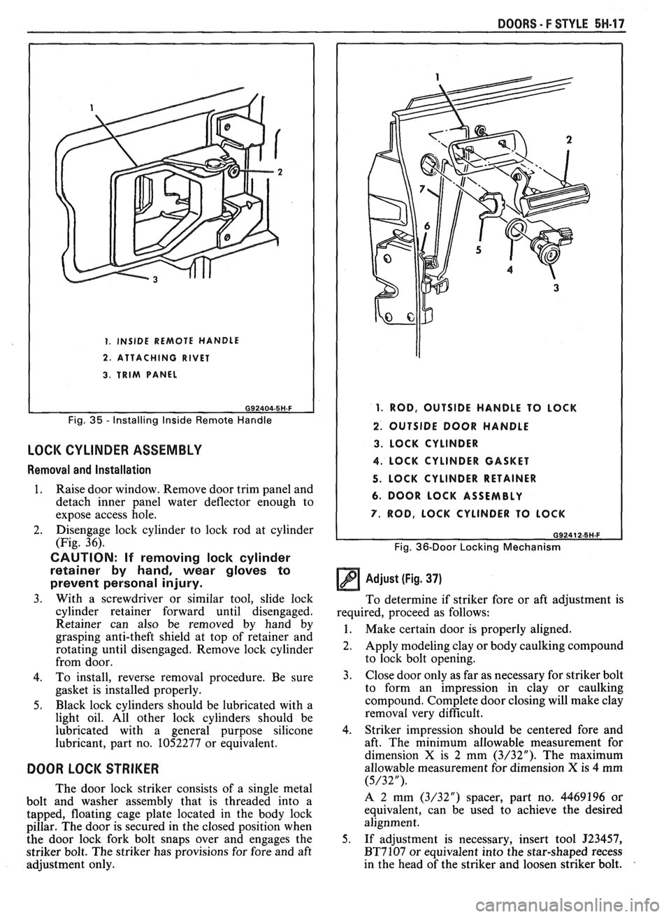
2. Remove outside handle to lock rod by
disengaging clip on outside handle (Fig. 36).
3. Remove two attaching nuts on handle studs.
4. Rotate handle up to disengage from attaching
holes.
5. To install, reverse removal procedure.
Page 1730 of 1825
DOORS - F STYLE 5W.17
1. INSIDE REMOTE HANDLE
2. ATTACHING RIVET
3. TRIM PANEL
Fig. 35 - Installing Inside Remote Handle
LOCK CYLINDER ASSEMBLY
Removal and Installation
1. Raise door window. Remove door trim panel and
detach inner panel water deflector enough to
expose access hole.
2. Disengage lock cylinder
to lock rod at cylinder
(Fig. 36).
CAUTION: If removing lock cylinder
retainer by hand, wear gloves to
prevent personal injury.
3. With a screwdriver or similar tool, slide lock
cylinder retainer forward until disengaged.
Retainer can also be removed by hand by
grasping anti-theft shield at top of retainer and
rotating until disengaged. Remove lock cylinder
from door.
4. To install, reverse removal procedure. Be sure
gasket is installed properly.
5. Black lock cylinders should be lubricated with a
light oil. All other lock cylinders should be
lubricated with a general purpose silicone
lubricant, part no. 1052277 or equivalent.
DOOR LOCK STRIKER
The door lock striker consists of a single metal
bolt and washer assembly that is threaded into a
tapped, floating cage plate located in the body lock
pillar. The door is secured in the closed position when
the door lock fork bolt snaps over and engages the
striker bolt. The striker has provisions for fore and aft
adjustment only.
1. ROD, OUTSIDE HANDLE TO LOCK
2. OUTSIDE DOOR HANDLE
3. LOCK CYLINDER
4. LOCK CYLINDER GASKET
5. LOCK CYLINDER RETAINER
6. DOOR LOCK ASSEMBLY
7. ROD, LOCK CYLINDER TO LOCK
G92412-5H.F
Fig. 36-Door Locking Mechanism
Adjust (Fig. 37)
To determine if striker fore or aft adjustment is
required, proceed as follows:
1. Make certain door is properly aligned.
2. Apply modeling clay or body caulking compound
to lock bolt opening.
3. Close
door only as far as necessary for striker bolt
to form an impression in clay or caulking
compound. Complete door closing will make clay
removal very difficult.
4. Striker impression should be centered fore and
aft. The minimum allowable measurement for
dimension
X is 2 mm (3/32"). The maximum
allowable measurement for dimension
X is 4 mm
(5/32").
A 2 mm (3/32") spacer, part no. 4469196 or
equivalent, can be used to achieve the desired
alignment.
5. If adjustment is necessary, insert tool
J23457,
BT7107 or equivalent into the star-shaped recess
in the head of the striker and loosen striker bolt.
Page 1733 of 1825
5H-20 DOORS - F STYLE
Removal and Installation
1.
Raise door window. Remove door trim panel and
inner panel water deflector.
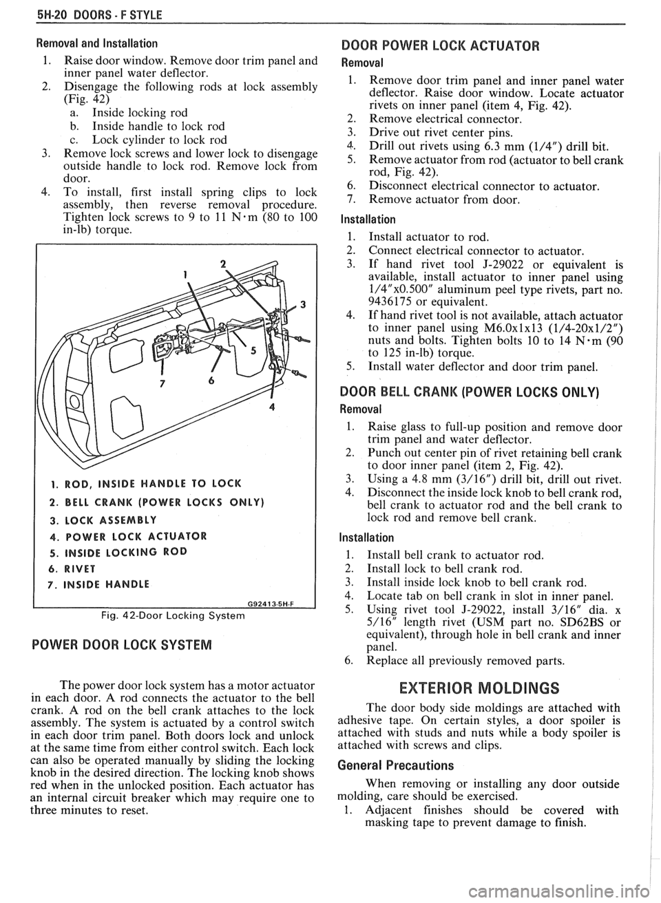
2. Disengage the following rods at lock assembly
(Fig. 42)
a. Inside locking rod
b. Inside handle to lock rod
c. Lock cylinder to lock rod
3. Remove lock screws and lower lock to disengage
outside handle to lock rod. Remove lock from
door.
4. To install, first install spring clips to lock
assembly, then reverse removal procedure.
Tighten lock screws to 9 to
11 Nem (80 to 100
in-lb) torque.
1. ROD, INSIDE HANDLE TO LOCK
2. BELL CRANK (POWER LOCKS ONLY)
3. LOCK ASSEMBLY
4. POWER LOCK ACTUATOR
4. INSIDE LOCKING ROD
6. RIVET
7. INSIDE HANDLE
G92413-5H-F
Fig. 42-Door Locking System
POWER DOOR LOCK SYSTEM
The power door lock system has a motor actuator
in each door.
A rod connects the actuator to the bell
crank. A rod on the bell crank attaches to the lock
assembly. The system is actuated by a control switch
in each door trim panel. Both doors lock and unlock
at the same time from either control switch. Each lock
can also be operated manually by sliding the locking
knob in the desired direction. The locking knob shows
red when in the unlocked position. Each actuator has
an internal circuit breaker which may require one to
three minutes to reset.
DOOR POWER LOCK ACTUATOR
Removal
Remove door trim panel and inner panel water
deflector. Raise door window. Locate actuator
rivets on inner panel (item
4, Fig. 42).
Remove electrical connector.
Drive out rivet center pins.
Drill out rivets using 6.3 mm
(1/4") drill bit.
Remove actuator from rod (actuator to bell crank
rod, Fig. 42).
Disconnect electrical connector to actuator.
Remove actuator from door.
Installation
1. Install actuator to rod.
2. Connect electrical connector to actuator.
3. If hand rivet tool J-29022 or equivalent is
available, install actuator to inner panel using
1/4"x0.500" aluminum peel type rivets, part no.
9436175 or equivalent.
4. If hand rivet tool is not available, attach actuator
to inner panel using
M6.0~1~13 (1/4-20x1/2")
nuts and bolts. Tighten bolts 10 to 14 N-m (90
to 125 in-lb) torque.
5. Install water deflector and door trim panel.
DOOR BELL CRANK (POWER LOCKS ONLY)
Removal
1.
Raise glass to full-up position and remove door
trim panel and water deflector.
2. Punch out center pin of rivet retaining bell crank
to door inner panel (item 2, Fig. 42).
3. Using a
4.8 mm (3/16") drill bit, drill out rivet.
4. Disconnect the inside
lock knob to bell crank rod,
bell crank to actuator rod and the bell crank to
lock rod and remove bell crank.
Installation
1.
Install bell crank to actuator rod.
2. Install lock to bell crank rod.
3. Install inside lock knob to bell crank rod.
4. Locate tab on bell crank in slot in inner panel.
5. Using rivet tool J-29022, install 3/16" dia. x
5/16" length rivet (USM part no.
SD62BS or
equivalent), through hole in bell crank and inner
panel.
6. Replace all previously removed parts.
EXTERIOR MOLDINGS
The door body side moldings are attached with
adhesive tape. On certain styles, a door spoiler is
attached with studs and nuts while a body spoiler is
attached with screws and clips.
General Precautions
When removing or installing any door outside
molding, care should be exercised.
1. Adjacent finishes should be covered with
masking tape to prevent damage to finish.