1988 PONTIAC FIERO window
[x] Cancel search: windowPage 1748 of 1825
REAR END. F STYLE 9H-5
a. Install
bolts - gas support to body at right
and left-hand gas supports. Make sure
electrical connector is facing inboard.
Torque bolts 20 to 28
N.m (15 to 20 ft-lb),
Figure 4, view
B).
b. Connect
electrical connector to gas support
(if present).
c. Install
bolts at rear of gas supports to lower
reinforcement. Torque bolts 5 to 7
N-m (40
to
60 in-lb) and connect electrical connector
(if present), Figure 4, view A.
14. Lift lid
and remove jackstands from body.
15. Install
a. Striker to panel
b. Wiper
motor and blade assembly. Torque
nut retaining wiper motor to glass 5 to 7
N-m (40 to 60 in-lb).
16. Align lock
a. Carefully
close lid and check striker-to-lock
engagement.
b. If
striker does not engage lock correctly,
loosen rear end trim panel and loosen bolts
holding lock assembly to rear end panel. If
equipped with electric lock release solenoid,
loosen bolt holding solenoid to rear end
panel.
c. Adjust lock for proper engagement to
striker.
d. Tighten lock and solenoid retaining bolts 9
to 12
N.m (7 to 9 ft-lb).
e. Replace rear end trim panel.
17. Replace lift window trim panel,
Glass Replacement and Adjustment
CAUTION: When removing glass
assemblies from car, the use of
personal protection items such as
work gloves and safely glasses is
recommended to minimize possible
personal injury.
Removal
1. Place protective covering along edges of rear
compartment to prevent damage to painted
surfaces.
2. If glass
is broken, remove all broken glass from
interior of car.
3. From
inside of car, remove plastic covers from
bolts holding gas supports to body.
4. If equipped with heated
back glass, remove wire
connectors from gas supports.
a. Unlock compartment lift window.
b. Have helper support lid in partially open
position.
5. Remove
a. Bolts holding
gas supports to body
b. Back body opening upper
garnish molding
c. Nuts
retaining lift window hinge to body
(Fig. 3)
6. With aid of helper remove lift window from car
and place upside down on a protected surface.
Note position of hinge shims (if present). 7.
Remove
a. Gas supports from lower reinforcement
(view A, Fig. 4)
b. Hinge assemblies from glass
c. Trim panel
d. Wiper and blade assembly (if present)
e. Lock striker
f. Electrical contact and wiring harness (if
present)
g. Lower reinforcement (1, Fig. 5)
h. Screws holding glass finishing molding to
panel
i. Nylon patches at radius joint of panel (Cut
through adhesive using a curved blade
utility knife.)
8. With aid of helper, turn lift window over and
place masking tape along top edge of panel.
a. If glass is being replaced for any reason
other than breakage, use a flat-bladed sharp
tool to cut out foam and butyl sealing strips
between panel and glass. Clean tool
frequently to ease cutting operation.
b. Lift upward on panel and pull from glass,
being careful not to distort ends of glass
molding.
9. Clean panel of foam sealing strip and all
adhesives. This can be done by using a cloth
dampened in alcohol.
10. Remove lower glass sealing strips (4, Fig.
5).
11. Remove
and discard plastic spacers.
Installation
1. When a new glass is installed, new glass finishing
moldings will be required. Use the following steps
to install moldings to glass.
a. Use clear
primer in urethane kit (9636067
or equivalent). Apply primer to glass as
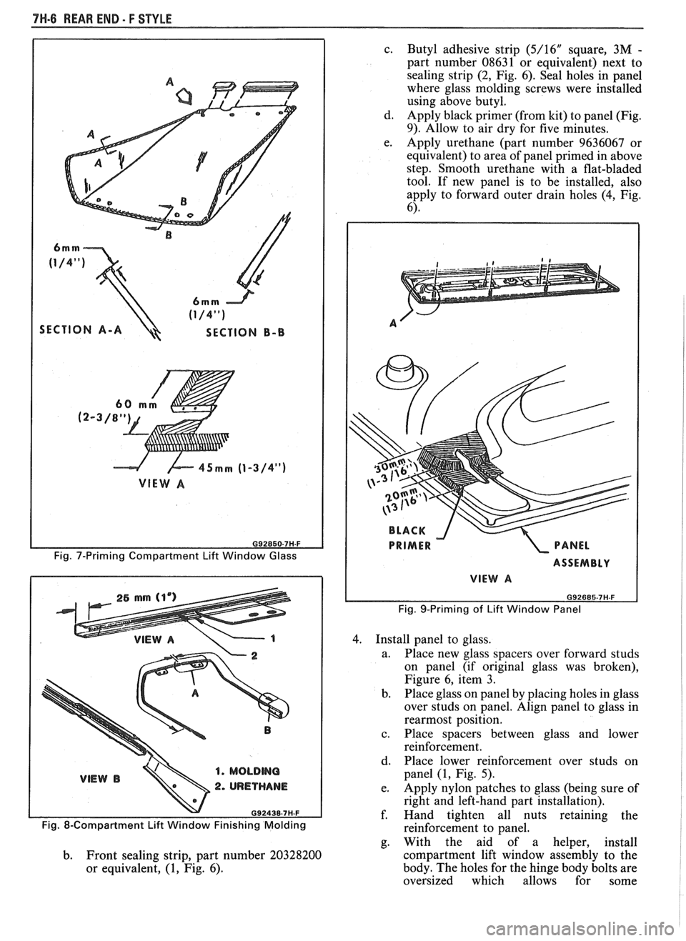
shown in Figure 7.
b. Apply a 4.5
mm
(3/16") bead of urethane
from kit into molding channel as shown in
Figure 8. Do not apply urethane for a
distance of 25 mm (1") from center end of
each molding.
c. Place molding escutcheon inside right and
left-hand moldings.
d. Use
a rubber mallet and install moldings
onto glass making sure to align holes in tabs
of molding with holes in glass. Be sure
corner area is fully seated.
CAUTION: When performing next
step, overtightening could cause glass
to break and possible personal injury.
The use of personal protection items
such as safety glasses and work
gloves is recommended to minimize
possible personal in jury.
2. Install hinge to glass and torque bolts 16 N m (1 1
ft-lb).
3. Install the following items:
a. Glass to reinforcement seals to rear edge of
glass (4, Fig. 5).
Page 1749 of 1825
7H-6 REAR END - F STYLE
SECTION A-A SECTION B-B
G92850-7H-F
Fig. 7-Priming Compartment Lift Window Glass
1. MOLDING
2. URETHANE
c.
Butyl adhesive strip (5/16" square, 3M -
part number 08631 or equivalent) next to
sealing strip
(2, Fig. 6). Seal holes in panel
where glass molding screws were installed
using above butyl.
d. Apply black primer (from kit) to panel (Fig.
9). Allow to air dry for five minutes.
e. Apply urethane (part number 9636067 or
equivalent) to area of panel primed in above
step. Smooth urethane with a flat-bladed
tool. If new panel is to be installed, also
apply to forward outer drain holes (4, Fig.
6).
ASSEMBLY
VIEW A
Fig. 9-Priming of Lift Window Panel
4. Install panel to glass.
a. Place new glass spacers over forward studs
on panel (if original glass was broken),
Figure 6, item
3.
b.
Place glass on panel by placing holes in glass
over studs on panel. Align panel to glass in
rearmost position.
c. Place spacers between glass and lower
reinforcement.
d. Place lower reinforcement over studs on
panel
(1, Fig. 5).
e. Apply nylon patches to glass (being sure of
right and left-hand part installation).
f. Hand tighten all nuts retaining the
Fig. 8-Compartment Lift Window Finishing Molding reinforcement to panel.
g. With the aid of a helper, install
b. Front sealing strip, part number 20328200 compartment
lift window assembly to the
or equivalent, (1, Fig. 6). body.
The holes for the hinge body bolts are
oversized which allows for some
Page 1750 of 1825
REAR END - F STYLE 761-7
adjustment. Install original hinge shims to
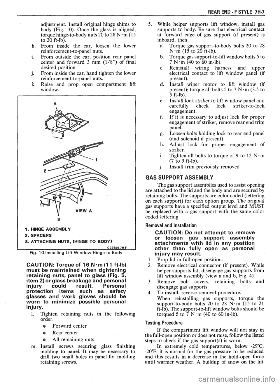
body (Fig. 10). Once the glass is aligned,
torque hinge-to-body nuts 20 to 28
N-m (15
to 20 ft-lb).
h. From inside the car, loosen the lower
reinforcement-to-panel nuts.
i. From outside the car, position rear panel
center and forward 3 mm
(1/8") of final
desired position.
j. From
inside the car, hand tighten the lower
reinforcement-to-panel nuts.
k. Raise and prop open compartment lift
window.
1. HlNQE ASSEMBLY
2. SPACERS
3. ATTACHHQ NUTS, (HINBE TO BODY)
Fig. 10-Installing Lift Window Hinge to Body
CAUTION: Torque of 16 N-m (I I ft-lb)
must be maintained when tightening
retaining nuts, panel to glass (Fig.
5,
item 2) or glass breakage and personal
injury could result. Personal
protection
items such as safety
glasses and
work gloves should be
worn to minimize possible personal
injury.
1. Tighten retaining nuts in the follo~
order:
ea Forward center
e Rear center
e All remaining nuts
m. Install screws securing glass finishing
molding to panel. It may be necessary to
drill two small holes in panel for molding
retaining screws.
5. While helper supports lift window, install gas
supports to body.
Be sure that electrical contact
at forward edge of gas support (if present) is
inboard, then
a. Torque gas support-to-body bolts 20 to 28
N.m (15 to 20 ft-lb).
b. Torque gas support-to-lift window bolts
5 to
7 N-m (40 to 60 in-lb).
c. Reinstall wiring harness and upper
electrical contact to lift window panel
(~f
present).
d. Install wiper motor to lift window (if
present); torque all bolts
5 to 7 N-m (3.5 to
5 ft-lb).
e. Install lock striker to lift window panel and
carefully check lock striker-to-lock
engagement.
f. If it is necessary to adjust lock for proper
engagement of striker, remove rear end trim
panel.
g. Loosen bolts
holding lock to rear end panel
(and solenoid if present).
h. Adjust lock for proper engagement of
striker.
i. Tighten all bolts to torque of 9 to 12 N-m
(7 to 9 ft-lb).
j. Install trim previously removed.
GAS SUPPORT ASSEMBLY
The gas support assemblies used to assist opening
are attached to the lid and the body and are secured by
retaining bolts. The supports are color coded (lettering
on each support) for each option group. The original
gas supports have a specified output level and MUST
be replaced with a gas support with the same color
coded lettering
Removal and Installation
CAUTION:
Do not attempt Po remove
or loosen gas support assembly
attachments with lid in any position
other than fully open as personal
injury may result.
1. Prop lid in full-open position.
2. Remove
electrical connector (if present). While
helper supports lid, disengage gas supports from
lift window assembly (view a and b, Fig. 4).
3. Remove bolt covers, retaining bolts and
disengage gas supports.
4. To install, reverse removal procedure.
When reinstalling gas supports, torque the
support-to-body bolts 20 to 28
N-m (15 to 21
ft-lb). The support-to-lift window bolts should be
torqued 5 to
7 N-m (40 to 60 in-lb).
Testing Procedure
If the compartment lift window will not stay in
the full-open position or does not raise, follow the listed
steps to check if the gas
support(s) is worn.
In extremely cold temperatures, below
-29"C,
-20"F, it is normal for the gas pressure to be reduced
and this results in a decrease in the hold-open force
until warmer weather.
A buildup of snow on the lift
Page 1751 of 1825
7H-8 REAR END - F STYLE
window will affect the ability of the gas supports to
hold the lift window open.
1. If the gas support system is not working properly,
get a correct replacement part. Very seldom do
gas supports wear out at the same time.
2. Replace a gas support on one side of the car.
3. If lift window falls down, reinstall on the other
side the support removed in step 2.
4. If lift window falls down, replace the support
installed in step 3 with a new gas support.
COMPARTMENT LIB LOCK CYLINDER
The compartment lid lock cylinder on some
models is located in the rear end panel behind the
license plate. On other models, it is in the center rear
end filler section.
The basic method of cylinder attachment where
the lock cylinder is located behind the license plate is
by means of a lock cylinder retainer. Styles with the
lock cylinder in the rear end filler use rivets to retain
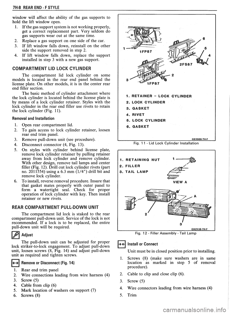
the lock cylinder (Fig. 11).
Removal and lnstallation
1. Open rear compartment lid.
2. To
gain access to lock cylinder retainer, loosen
rear end trim panel.
3. Remove pull-down unit (see procedure).
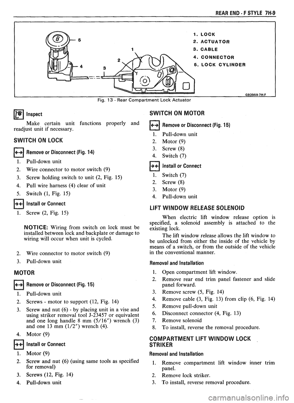
4. Disconnect connector (4, Fig. 13).
5. On
styles with cylinder behind license plate,
remove lock cylinder retainer by pulling retainer
away from lock cylinder and remove cylinder.
With other design, remove tail lamps and center
filler (Fig. 12). Drill out lock cylinder rivets (part
no. 201 1554) using a 6.3 mm
(1/4") drill bit and
remove lock cylinder.
6. To install, reverse removal procedure. Insure that
that gasket mates properly with outer panel to
form a watertight seal. Check for proper
operation of lock cylinder with key. Then install
retainer or new rivets.
REAR COMPARTMENT PULL-DOWN UNIT
The compartment lid lock is staked to the rear
compartment pull-down unit. Service of the lock is not
recommended. If a lock is to be replaced, the entire
pull-down unit will be required.
Adjust
The pull-down unit can be adjusted for proper
lock striker-to-lock engagement. To adjust pull-down
unit, loosen screws (8, Fig. 14) and adjust pull-down
unit as required and tighten screws.
Remove or Disconnect (Fig. 14)
1. Rear end trim panel
2. Wire connections leading from wire harness (4)
3. Screw (5)
4. Cable from clip (6)
5. Mark location of washers on support
(7)
6. Screws (8)
1. RETAINER - LOCK CYLINDER
2. LOCK CYLINDER
8. GASKET
4. RIVET
6. LOCK CYLINDER
6. GASKET
G93988-7H-F
Fig. 11 - Lid Lock Cylinder lnstallation
1. RETAINING NUT
2. FILLER
3. TAIL LAMP
VIEW A
Fig. 12 - Filler Assembly - Tail Lamp
Install or Connect
Unit must be in closed position prior to installing.
1. Screws (8) (make sure washers are in same
location as marked in step 5 of removal
procedure).
2. Cable
to clip and close clip (6).
3. Screw (5)
4. Wire connectors
leading from wire harness (4)
5. Trim
Page 1752 of 1825
REAR END - F STYLE 7H-9
4. CONNECTOR
1. LOCK CYLINDER
Fig. 13 - Rear Compartment Lock Actuator
Inspect SWITCH ON MOTOR
Make certain unit functions properly and Remove or Disconnect (Fig. 15)
readjust unit if necessary.
1. Pull-down unit
SWITCH ON LOCK 2. Motor (9)
Remove or Disconnect (Fig. 14)
1. Pull-down unit
2. Wire connector
to motor switch (9) 3.
Screw (8)
4. Switch (7) Install or Connect . .
3. Screw
holding switch to unit (2, Fig. 15) 1.
Switch (7)
4. Pull wire harness (4) clear of unit 2.
Screw (8)
3. Motor (9)
5. Switch
(1, Fig. 15)
4. Pull-down unit
lnstall or Connect
1. Screw (2, Fig. 15)
NOTICE: Wiring from switch on lock must be
installed between lock and backplate or damage to
wiring will occur when unit is cycled.
2. Wire connector
to motor switch (9)
3. Pull-down unit
MOTOR
Remove or Disconnect (Fig. 15)
1. Pull-down unit
2. Screws
- motor
to support (12, Fig. 14)
3. Screw
and nut (6)
- by placing unit in a vise and
using striker removal tool
5-23457 or equivalent
and one long handle 8 mm
(5/16") wrench (3)
and one 13 mm
(1/2") wrench (4).
4. Motor (9)
Install or Connect
1. Motor (9)
2. Screw and nut (6) (using same tools as specified
for removal)
3. Screws (12, Fig. 14)
4. Pull-down unit
LlFT WINDOW RELEASE SOLENOID
When electric lift window release option is
specified, a solenoid assembly is attached to the
existing lock.
The lift window release allows the lift window to
be unlocked from either the inside of the vehicle by
means of a switch, or from the outside of the vehicle
in the conventional manner.
Removal and Installation
1. Open compartment lift window.
2. Remove
rear end trim panel fastener and slide
panel forward.
3. Remove screw
(5, Fig. 14)
4. Remove
cable (3, Fig. 13) from clip (6, Fig. 14)
5. Remove pull-down unit
6. Disconnect connector (4, Fig. 13)
7. Remove solenoid
8. To install, reverse the removal procedure.
COMPARTMENT LlFT WINDOW LOCK
STRIKER
Removal and Installation
1. Remove
compartment lift window inner trim
panel.
2. Remove lock striker.
3. To install, reverse removal procedure.
Page 1754 of 1825
REAR END - I: STYLE 7H-11
COMPARTMENT WEATHERSTRIP
A clinch type weatherstrip is used on all styles.
The supersoft foam weatherstrip has an integral metal
reinforced section which grips and seals the
weatherstrip to the gutter flange.
Removal and lnstallation
1.
Separate butt joint at base of opening. Remove
and retain plug from old weatherstrip.
2. Peel weatherstrip from gutter flange toward
lower corners and then around complete opening.
3. To install, apply weatherstrip to pinchweld flange
and begin inserting center of weatherstrip
(marked with paint) onto the gutter flange at the
forward center of the opening between hinges. Be
sure clinch is completely seated to the flange
around the entire opening.
4. Cement butt ends together using plug from
original weatherstrip.
COMPARTMENT LlFT WINDOW PRIM PANEL
Removal and lnstallation (Fig. 16)
1. Remove screws.
2. Slide trim panel forward and pull-down on panel
to remove.
3. To install, reverse the removal procedure.
Fig. 16-Compartment Lift Window Trim Panel
LIFT WINDOW WIPER SYSTEM
MOTOR AND BLADE ASSEMBLY
Removal and lnstallation (Fig. 17)
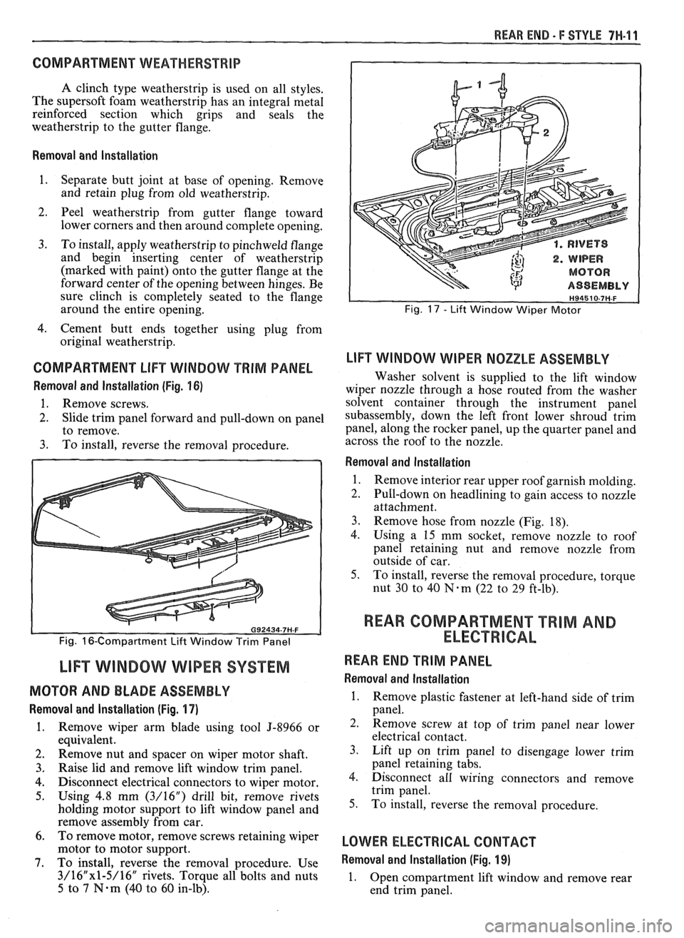
1. Remove wiper arm blade using tool 5-8966 or
equivalent.
2. Remove nut and spacer on wiper motor shaft.
3. Raise lid and remove lift window trim panel.
4. Disconnect electrical connectors to wiper motor.
5. Using 4.8 mm (3/16") drill bit, remove rivets
holding motor support to lift window panel and
remove assembly from car.
6. To
remove motor, remove screws retaining wiper
motor to motor support.
7. To install, reverse the removal procedure. Use
3/16"x1-5/16" rivets. Torque all bolts and nuts
5 to 7 N.m (40 to 60 in-lb).
. RIVETS
. WIPER
MOTOR
ASSEMBLY
Fig. 17 - Lift Window Wiper Motor
LlFT WINDOW WIPER NOZZLE ASSEMBLY
Washer solvent is supplied to the lift window
wiper nozzle through a hose routed from the washer
solvent container through the instrument panel
subassembly, down the left front lower shroud trim
panel, along the rocker panel, up the quarter panel and
across the roof to the nozzle.
Removal and lnstallation
1.
Remove interior rear upper roof garnish molding.
2. Pull-down on headlining to gain access to nozzle
attachment.
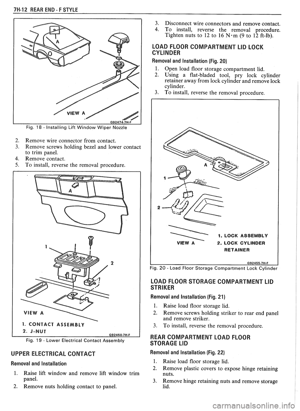
3. Remove hose from nozzle (Fig. 18).
4.
Using a 15 mm socket, remove nozzle to roof
panel retaining nut and remove nozzle from
outside of car.
5. To install, reverse the removal procedure, torque
nut
30 to 40 N-m (22 to 29 ft-lb).
REAR COMPARTMENT "TRIM AND
ELECTRICAL
REAR END TRIM PANEL
Removal and lnstallation
1. Remove plastic fastener at left-hand side of trim
panel.
2. Remove screw at top of trim panel near lower
electrical contact.
3. Lift up on trim panel to disengage lower trim
panel retaining tabs.
4. Disconnect all wiring connectors and remove
trim panel.
5. To install, reverse the removal procedure.
LOWER ELECTRICAL CONTACT
Removal and lnstallation (Fig. 19)
1.
Open compartment lift window and remove rear
end trim panel.
Page 1755 of 1825
7H-42 REAR END- F STYLE
Fig. 18 - Installing Lift Window Wiper Nozzle
2.
Remove wire connector from contact.
3. Remove screws holding bezel and lower contact
to trim panel.
4. Remove contact.
5. To install, reverse the removal procedure.
1. CONTACT ASSEMBLY
Fig. 19 - Lower Electrical Contact Assembly
UPPER ELECTRICAL CONTACT
Removal and lnstallation
1.
Raise lift window and remove lift window trim
panel.
2. Remove nuts holding contact to panel.
3. Disconnect wire connectors and remove contact.
4. To install, reverse the removal procedure.
Tighten nuts to 12 to
16 N-m (9 to 12 ft-lb).
LOAD FLOOR COMPARTMENT LID LOCK
CYLINDER
Removal and lnstallation (Fig. 20)
1.
Open load floor storage compartment lid.
2. Using a flat-bladed tool, pry lock cylinder
retainer away from lock cylinder and remove lock
cylinder.
3. To install, reverse the removal procedure.
1. LOCK ASSEMBLY
VIEW A 2. LOCK CYLINDER
Fig. 20 - Load Floor Storage Compartment Lock Cylinder
LOAD FLOOR STORAGE COMPARTMENT LID
STRIKER
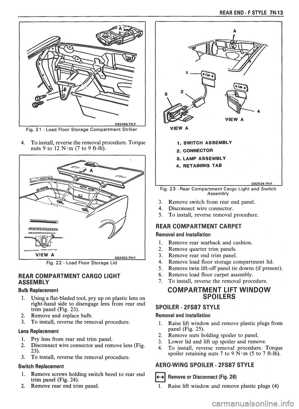
Removal and lnstallation (Fig. 21)
1.
Raise load floor storage lid.
2. Remove screws holding striker to rear end panel
and remove striker.
3. To install, reverse the removal procedure.
REAR COMPARTMENT LOAD FLOOR
STORAGE LID
Removal and lnstallation (Fig. 22)
1. Raise load floor storage lid.
2. Remove plastic covers to expose hinge retaining
nuts.
3. Remove hinge retaining nuts and remove storage
lid.
Page 1756 of 1825
REAR END - F STYLE 7W-13
Fig. 2 1 - Load Floor Storage Compartment Striker
4. To
install, reverse the removal procedure. Torque
nuts
9 to 12 N-m (7 to 9 ft-lb).
Fig. 22 - Load Floor Storage Lid
REAR COMPARTMENT CARGO LIGHT
ASSEMBLY
Bulb Replacement
1. Using a flat-bladed tool, pry up on plastic lens on
right-hand side to disengage lens from rear end
trim panel (Fig. 23).
2. Remove and replace bulb.
3. To install, reverse the removal procedure.
Lens Replacement
1. Pry lens from rear end trim vanel.
2. Disconnect wire connector and remove lens (Fig.
23).
3. ~d install, reverse the removal procedure.
Switch Replacement
1. Remove screws holding switch bezel to rear end
trim panel (Fig. 24).
2. Remove rear end trim panel.
VlEW A
1. SWITCH ASSEMBLY
2. CONNECTOR
8. LAMP ASSEMBLY
4. RETAINING TAB
Fig. 23 - Rear Compartment Cargo Light and Switch
Assembly
3. Remove
switch from rear end panel.
4. Disconnect wire connector.
5. To
install, reverse removal procedure.
WEAR COMPARTMENT CARPET
Removal and Installation
1. Remove rear seatback and cushion.
2. Remove quarter trim panels.
3. Remove rear end trim panel.
4. Remove load floor storage compartment lid.
5. Remove twin lift-off panel tie downs (if present).
6. Remove load floor carpet assembly.
7. To install, reverse the removal procedure.
GOMPARTMEN"FLlFT WINDOW
SPOILERS
SPOILER - 2FS87 STYLE
Removal and lnstallation
1. Raise lift window and remove plastic plugs from
panel (Fig. 25).
2. Remove nuts holding spoiler to panel.
3. Lower lid
and lift up spoiler and remove.
4. To install, reverse removal procedure. Torque
spoiler retaining nuts
7 to 9 N.m (5 to 7 ft-lb).
AERO-WING SPOILER - 2FS87 STYLE
a Remove or Disconnect (Fig. 26)
1. Raise lift window and remove plastic plugs (4)