1988 PONTIAC FIERO window
[x] Cancel search: windowPage 1623 of 1825
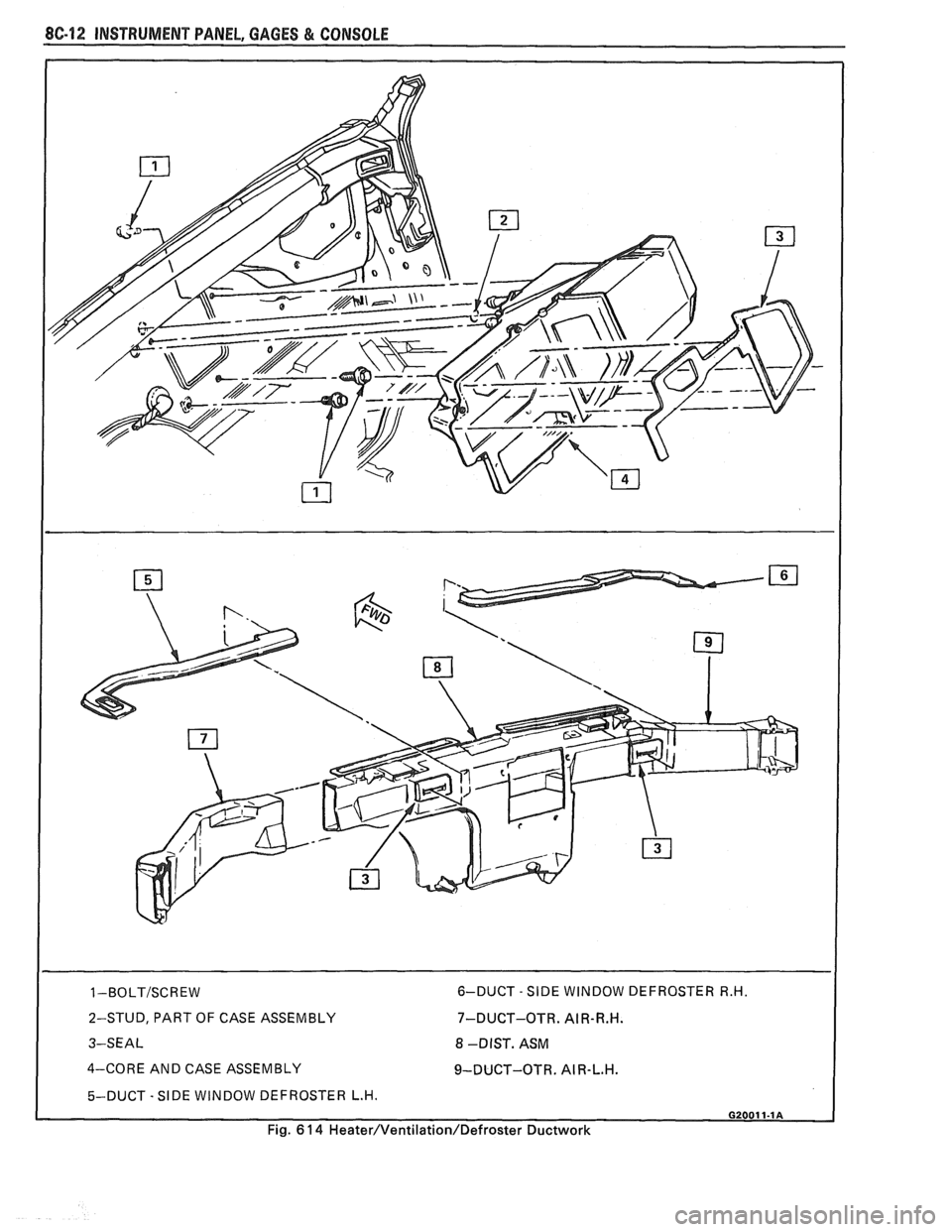
2-STUD, PART OF CASE ASSEMBLY
3-SEAL 7-DUCT-OTR.
AIR-R.H.
8 -DIST. ASM
4-CORE AND CASE ASSEMBLY
9-DUCT-OTR. AI R-L.H.
5-DUCT - SIDE WINDOW DEFROSTER L.H. I
Fig. 6 14 Heater/Ventilation/Defroster Ductwork
Page 1625 of 1825
8C14 INSTRUMENT PANEL, GAGES & CONSOLE
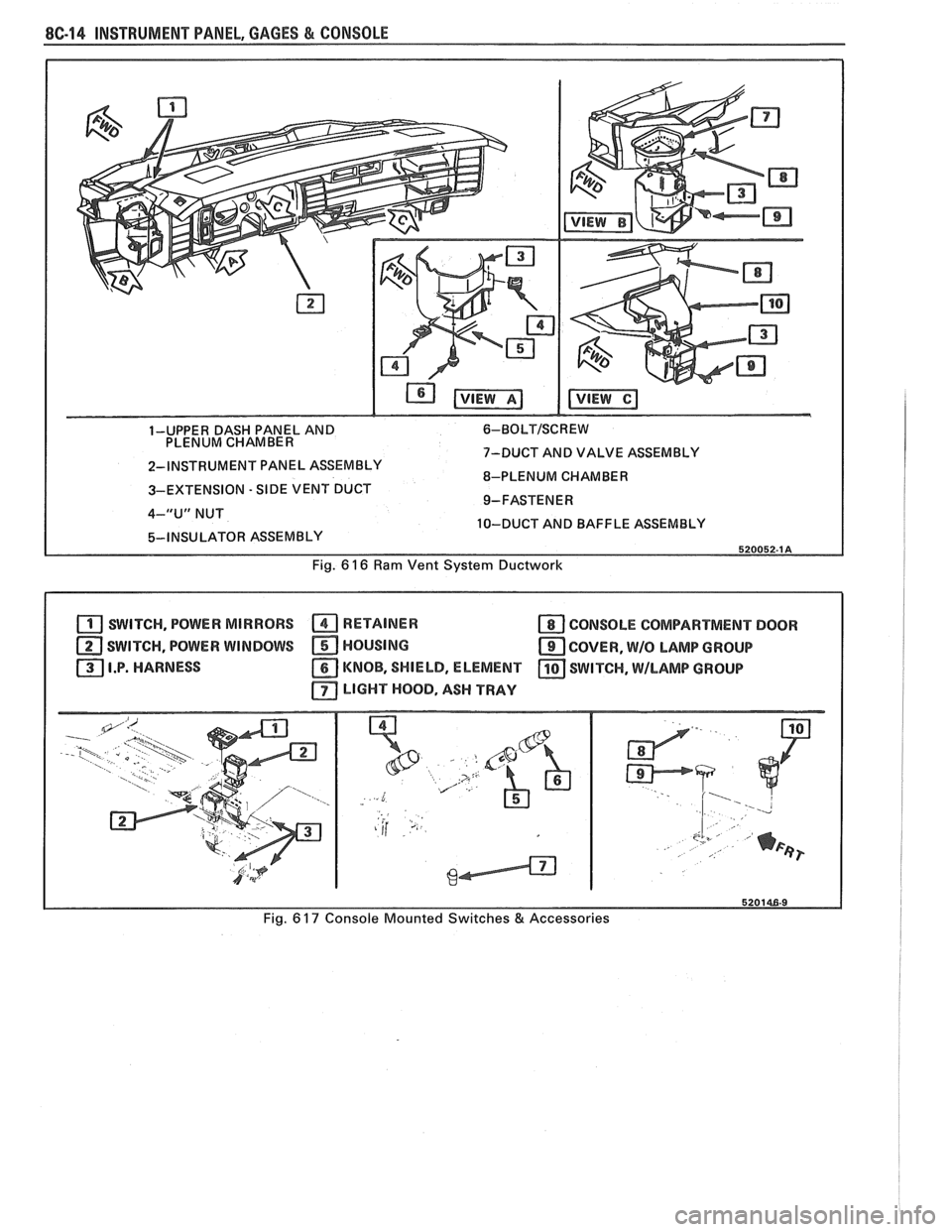
1-UPPER DASH PANEL AND 6-BOLTISCREW
PLENUM CHAMBER
7-DUCT AND VALVE ASSEMBLY
2-INSTRUMENT PANEL ASSEMBLY
8-PLENUM CHAMBER
3-EXTENSION
- SIDE VENT DUCT
4-"U" NUT
10-DUCT AND BAFFLE ASSEMBLY
Fig.
6 16 Ram Vent System Ductwork
SWITCH, POWER MIRRORS RETAINER a CONSOLE COMPARTMENT DOOR
SWITCH, POWER WINDOWS HOUSING
COVER, W/O LAMP GROUP
I.P. HARNESS
KNOB, SHIELD, ELEMENT SWITCH, \MILAMP GROUP
LIGHT HOOD, ASH TRAY
Fig. 6 17 Console Mounted Switches & Accessories
Page 1674 of 1825
MISCELLANEOUS ACCESSORIES 96-4
SCELLANEOUS ACCESSOR
General Description ................................. 9G-1
Rally Gages .................................................. 9G- 1
Tachometer ................................................. 9G- 1
Trip Odometer
............................................. 9G- 1
Electric Rear Window Defogger ................. 9G-2
Power Remote Control Rearview
Mirror ........................................................ 9G-2
Diagnosis .................................................... 9G-2
Rally Gages ............................................... 9G-2
Tachometer .................................... .... .... 9G-2
Electric Rear Window Defogger ................. 9G-2
Power Remote Control Rearview
Mirror ........................................................ 96-2
Dash and Console Mounted
Accessory Switches
................................. 9G-4
General Description .................................. 9G-4
Electronic Glare Control Mirror ................. 9G-4
On-Car Service ............................................. 9G-4
Rally Gages, Tach ....................................... 96-4.
Rear Window Defogger ............................ 96-4.
Power Remote Control Mirror .................... 9G-4
GENERAL BESCRIP"T0N
RALLY GAGES
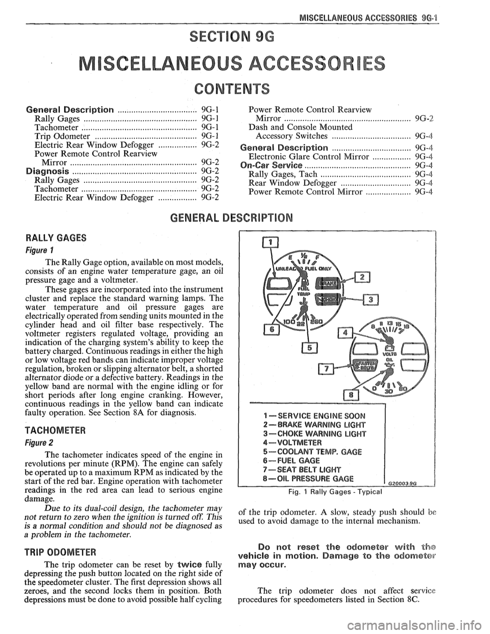
Figure I
The Rally Gage option, available on most models,
consists of an engine water temperature gage, an oil
pressure gage and a voltmeter.
These gages are incorporated into the instrument
cluster and replace the standard warning lamps. The
water temperature and oil pressure gages are
electrically operated from sending units mounted in the
cylinder head and oil filter base respectively. The
voltmeter registers regulated voltage, providing an
indication of the charging system's ability to keep the
battery charged. Continuous readings in either the high
or low voltage red bands can indicate improper voltage
regulation, broken or slipping alternator belt,
a shorted
alternator diode
or a defective battery. Readings in the
yellow band are normal with the engine idling or for
short periods after long engine cranking. However,
continuous readings in the yellow band can indicate
faulty operation. See Section
8A for diagnosis.
TACHOMETER
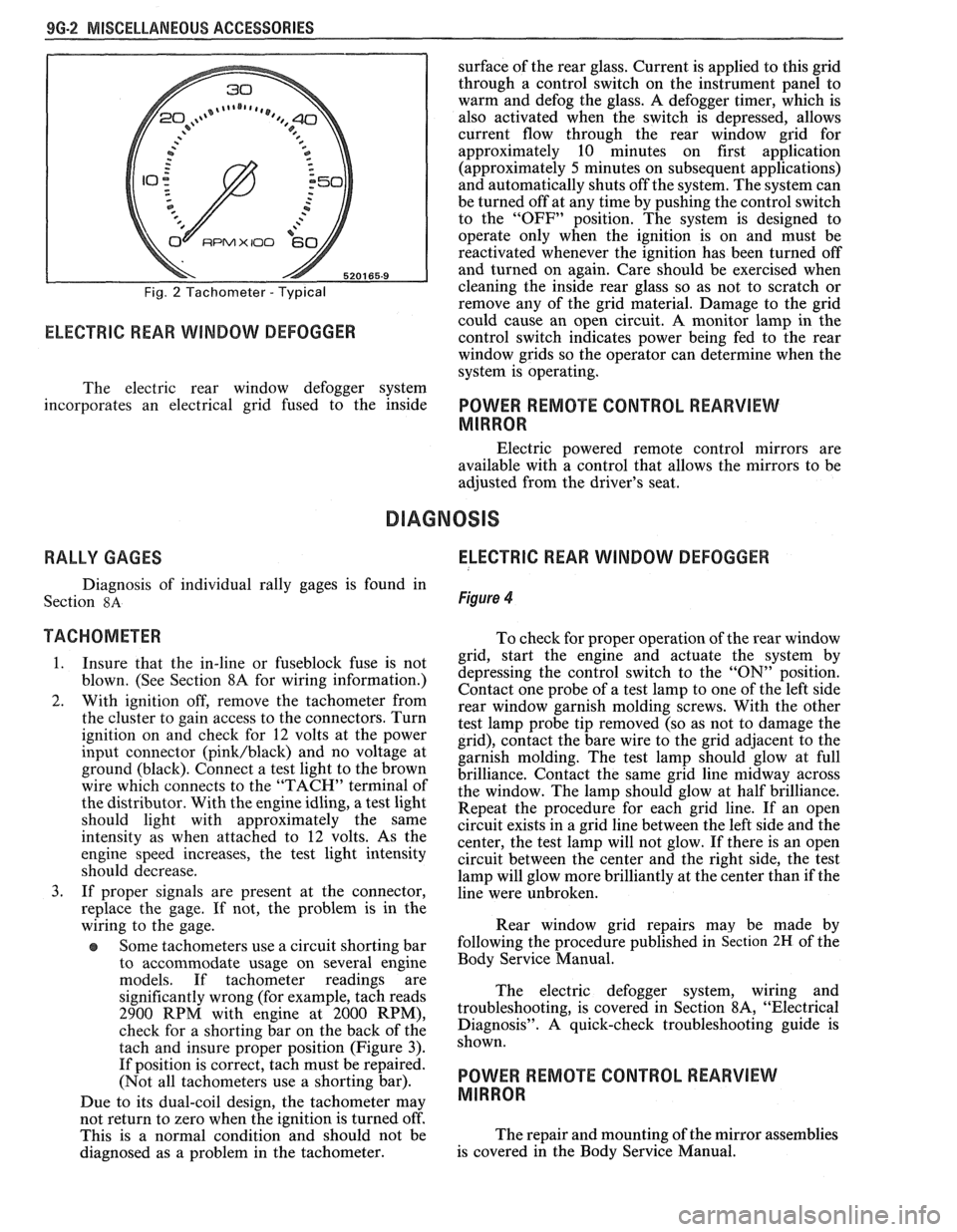
Figure 2
The tachometer indicates speed of the engine in
revolutions per minute (RPM). The engine can safely
be operated up to a maximum RPM as indicated by the
start of the red bar. Engine operation with tachometer
readings in the red area can lead to serious engine
damage.
Due to its dual-coil design, the tachometer may
not return to zero when the ignition
is turned oft: This
is
a normal condition and should not be diagnosed as
a problem in the tachometer.
TRIP ODOMETER
The trip odometer can be reset by twice fully
depressing the push button located on the right side of
the speedometer cluster. The first depression shows all
zeroes, and the second locks them in position. Both
depressions must be done to avoid possible half cycling
I -SERVICE ENGINE SOON
2-BRAKE WARNING LIGHT
3-CHOKE WARNING LIGHT
4-VOLTMETER
5-COOUNT TEMP. GAGE
6-FUEL GAGE
7-SEAT BELT LIGHT
8-OIL PRESSURE GAGE G20003 9G
Fig. 1 Rally Gages - Typical
of the trip odometer. A slow, steady push should be
used to avoid damage to the internal mechanism.
Do not reset the odometer with the
vehicle in motion. Damage to the odometer
may occur.
The trip odometer does not affect service
procedures for speedometers listed in Section
8C.
Page 1675 of 1825
9G-2 MISCELLANEOUS ACCESSORIES
Fig. 2 Tachometer - Typical
RPMX I00 €31-
ELECTRIC REAR WINDOW DEFOGGER
surface of the rear glass. Current is applied to this grid
through a control switch on the instrument panel to
warm and defog the glass. A defogger timer, which is
also activated when the switch is depressed, allows
current flow through the rear window grid
for
approximately 10 minutes on first application
(approximately
5 minutes on subsequent applications)
and automatically shuts off the system. The system can
be turned off at any time by pushing the control switch
to the "OFF" position. The system is designed to
operate only when the ignition is on and must be
reactivated whenever the ignition has been turned off
and turned on again. Care should be exercised when
cleaning the inside rear glass so as not to scratch or
remove any of the grid material. Damage to the grid
could cause an open circuit. A monitor lamp in-the
control switch indicates power being fed to the rear
window grids so the operator can determine when the
system is operating.
The electric rear window defogger system
incorporates an electrical grid fused to the inside
POWER REMOTE CONTROL REARVIEW
MIRROR
Electric powered remote control mirrors are
available with a control that allows the mirrors to be
adjusted from the driver's seat.
RALLY GAGES ELECTRIC REAR WINDOW DEFOGGER
Diagnosis of individual rally gages is found in
Section
8A Figure 4
TACHOMETER To check for moper o~eration of the rear window
1. Insure that the in-line or fuseblock fuse is not
blown. (See Section 8A for wiring information.)
2. With ignition off, remove the tachometer from
the cluster to gain access to the connectors. Turn
ignition on and check for
12 volts at the power
input connector
(pink/black) and no voltage at
ground (black). Connect a test light to the brown
wire which connects to the "TACH" terminal of
the distributor. With the engine idling, a test light
should light with approximately the same
intensity as when attached to
12 volts. As the
engine speed increases, the test light intensity
should decrease.
3. If proper signals are present at the connector,
replace the gage. If not, the problem is in the
wiring to the gage.
Some tachometers use a circuit shorting bar
to accommodate usage on several engine
models. If tachometer readings are
significantly wrong (for example, tach reads
2900 RPM with engine at 2000 RPM),
check for a shorting bar on the back of the
tach and insure proper position (Figure
3).
If position is correct, tach must be repaired.
(Not all tachometers use a shorting bar).
Due to its dual-coil design, the tachometer
may
- grid, start the engine a& actuate the system by
depressing the control switch to the
"ON" position.
Contact one probe of a test lamp to one of the left side
rear window garnish molding screws. With the other
test lamp probe tip removed (so as not to damage the
grid), contact the bare wire to the grid adjacent to the
garnish molding. The test lamp should glow at full
brilliance. Contact the same grid line midway across
the window. The lamp should glow at half brilliance.
Repeat the procedure for each grid line. If an open
circuit exists in a grid line between the left side and the
center, the test lamp will not glow. If there is an open
circuit between the center and the right side, the test
lamp will glow more brilliantly at the center than if the
line were unbroken.
Rear window grid repairs may be made by
following the procedure published in
Section 2H of the
Body Service Manual.
The electric defogger system, wiring and
troubleshooting, is covered in Section
8A, "Electrical
Diagnosis". A quick-check troubleshooting guide is
shown.
POWER REMOTE CONTROL REARVIEW
MIRROR
not return to zero when tvhe ignition is turned off'.
This is a normal condition and should not be The
repair and mounting of the mirror assemblies
diagnosed as a problem in the tachometer. is
covered in the Body Service Manual.
Page 1677 of 1825
96.4 MISCELLANEOUS ACCESSORIES
DASH AND CONSOLE MOUNTED ACCESSORY
SWITCHES
Installation for various dash and console
mounted accessory switches is shown in Section
8C.
GENERAL DESCRIPIIOM
ELECTRONIC GLARE CONTROL MIRROR
Service procedures regarding this mirror are
found in the Body Section of this manual.
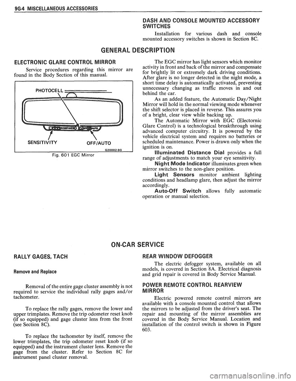
Fig. 601 EGC Mirror
The EGC mirror has light sensors which monitor
activity in front and back of the mirror and compensate
for brightly lit or extremely dark driving conditions.
After glare is no longer detected in the night mode, a
short time delay is automatically activated, preventing
unnecessary changing as traffic moves in and out
behind the car.
As an added feature, the Automatic
Day/Night
Mirror will hold in the normal viewing mode whenever
the shift selector is placed in reverse. This assures you
of a bright, clear view while backing up.
The Automatic Mirror with EGC (Electornic
Glare Control) is a technological breakthrough using
advanced computer circuitry. It is powered by the
vehicle electrical system and requires no batteries or
scheduled maintenance. Power is drawn only when the
ignition is on.
Illuminated Distance Dial provides a full
range of adjustments to match your eye sensitivity.
Night Mode Indicator illuminates green when
mirror switches to the non-glare position.
Light Sensors monitor ambient lighting
conditions and
headlamp glare, then adjust the mirror
accordingly.
Auto-Off Switch allows fully automatic
operation or manual selection.
ON-CAR SERVICE
RALLY GAGES, TACH REAR WINDOW DEFOGGER
Remove
and Replace
The electric defogger system, available on all
models, is covered in Section
8A. Electrical diagnosis
and grid repair is covered in Body Service Manual.
Removal of the entire gage cluster assembly is not
POWER RmOTE CONTROL REARVIEW
required to service the individual rally gages and/or MIRROR
tachometer.
Electric powered remote control mirrors are
available with a console mounted control that allows
To replace the rally gages, remove the lower and the
mirrors to be adjusted from the driver's seat. The
upper trimplates. Remove the trip odometer reset knob repair
and mounting of the mirror assemblies are
(if so equipped) and gage cluster lens from the front covered in
the Body Service Manual. Location and
(see Section
8C). installation of the control switch is shown in Figure
603.
To replace the tachometer by itself, remove the
lower trimplates, the trip odometer reset knob (if so
equipped) and the instrument cluster lens. Remove the
gage from the cluster. Refer to Section
8C for
hstrument panel cluster removal.
Page 1685 of 1825
1H-4 GENERAL INFORMATION - F STYLE
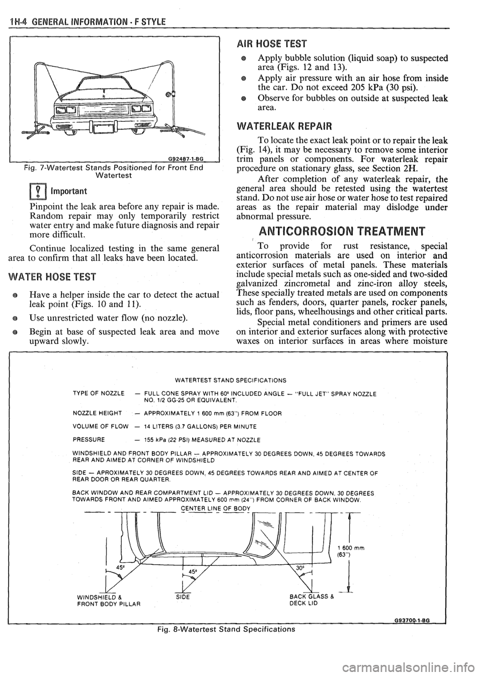
Fig. 7-Watertest Stands Positioned for Front End
Watertest
Important
Pinpoint the leak area before any repair is made.
Random repair may only temporarily restrict
water entry and make future diagnosis and repair
more difficult.
Continue localized testing in the same general
area to confirm that all leaks have been located.
WATER HOSE TEST
e Have a helper inside the car to detect the actual
leak point (Figs. 10 and 11).
Use unrestricted water flow (no nozzle).
Begin at base of suspected leak area and move
upward slowly.
AIR HOSE TEST
Apply bubble solution (liquid soap) to suspected
area (Figs. 12 and 13).
Apply air pressure with an air hose from inside
the car. Do not exceed 205
kPa (30 psi).
Observe for bubbles on outside at suspected leak
area.
WATERLEAK REPAIR
To locate the exact leak point or to repair the leak
(Fig.
14), it may be necessary to remove some interior
trim panels or components. For waterleak repair
procedure on stationary glass, see Section
2H.
After completion of any waterleak repair, the
general area should be retested using the watertest
stand. Do not use air hose or water hose to test repaired
areas as the repair material may dislodge under
abnormal pressure.
ANTICORROSION TREATMENT 1 To provide for rust resistance, special
anticorrosion materials are
used on interior and
exterior surfaces of metal panels. These materials
include special metals such as one-sided and two-sided
galvanized zincrometal and zinc-iron alloy steels,
These specially treated metals are used on components
such as fenders, doors, quarter panels, rocker panels,
lids, floor pans, wheelhousings and other critical parts.
Special metal conditioners and primers are used
on interior and exterior surfaces along with protective
waxes on interior surfaces in areas where moisture
WATERTEST STAND SPECIFICATIONS
TYPE OF NOULE
- FULL CONE SPRAY WITH 60' INCLUDED ANGLE - "FULL JET" SPRAY NOZZLE
NO. 112 GG-25 OR EQUIVALENT
NOULE HEIGHT - APPROXIMATELY 1 600 mrn (63") FROM FLOOR
VOLUME OF FLOW
- 14 LITERS (3.7 GALLONS) PER MINUTE
PRESSURE
- 755 kPa (22 PSI) MEASURED AT NOZZLE
WINDSHIELD AND FRONT BODY PILLAR
- APPROXIMATELY 30 DEGREES DOWN, 45 DEGREES TOWARDS
REAR AND AIMED AT CORNER OF WINDSHIELD
StDE - APROXIMATELY 30 DEGREES DOWN, 45 DEGREES TOWARDS REAR AND AIMED AT CENTER OF
REAR DOOR OR REAR QUARTER
BACK WINDOW AND REAR COMPARTMENT LID
- APPROXIMATELY 30 DEGREES DOWN. 30 DEGREES
TOWARDS FRONT AND AIMED APPROXIMATELY 600 rnm (24") FROM CORNER OF BACK WINDOW
CENTER
LINJ OF BODY - --
WINDSHIELD 8. SIDE BACK GLASS & FRONT BODY PILLAR DECK
LID
Fig. &Watertest Stand Specifications
Page 1688 of 1825
GENERAL INFORMATION - F STYLE IN-7
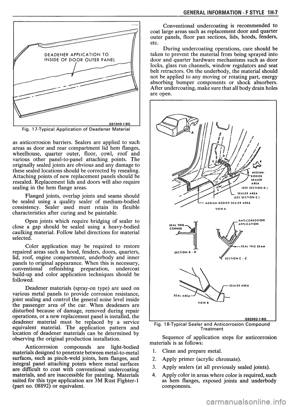
DEADENER APPLICATION TO
INSIDE OF DOOR OUTER PANEL
I I
Fig. 17-Typical Application of Deadener Material
as anticorrosion barriers. Sealers are applied to such
areas as door and rear compartment lid hem flanges,
wheelhouse, quarter outer, floor, cowl, roof and
various other panel-to-panel attaching points. The
originally sealed joints are obvious and any damage to
these sealed locations should be corrected by resealing.
Attaching points of new replacement panels should be
resealed. Replacement lids and doors will also require
sealing in the hem flange areas.
Flanged joints, overlap joints and seams should
be sealed using a quality sealer of medium-bodied
consistency. Sealer used must retain its flexible
characteristics after curing and be paintable.
Open joints which require bridging of sealer to
close a gap should be sealed using a heavy-bodied
caulking material. Follow label directions for material
selected.
Color application may be required to restore
repaired areas such as hood, fenders, doors, quarters,
lid, roof, engine compartment, underbody and inner
panels to original appearance. When this is necessary,
conventional refinishing preparation, undercoat
build-up and color application techniques should be
followed.
Deadener materials (spray-on type) are used on
various metal panels to provide corrosion resistance,
joint sealing and control the general noise level inside
the passenger area of the car. When deadeners are
disturbed because of damage, removed during repair
operations, or a new replacement panel is installed, the
deadener material must be replaced by a service
equivalent material. The application pattern and
location of deadener materials can be determined by
observing the original production installation.
Anticorrosion compounds are light-bodied
materials designed to penetrate between metal-to-metal
surfaces, such as pinch-weld joints, hem flanges, and
integral panel attaching points where metal surfaces
are difficult to coat with conventional undercoating
materials, and are inaccessible for painting. Materials
suited for this type application are
3M Rust Fighter-1
(part no. 08892) or equivalent. Conventional
undercoating is recommended to
coat large areas such as replacement door and quarter
outer panels, floor pan sections, lids, hoods, fenders,
etc.
During undercoating operations, care should be
taken to prevent the material from being sprayed into
door and quarter hardware mechanisms such as door
locks, glass run channels, window regulators and seat
belt retractors. On the underbody, the material should
not be applied to any moving or rotating part, energy
absorbing bumper components or shock absorbers.
After undercoating, make sure that all body drain holes
are open.
SEAL THIS SEAM
SECTION
D - 0
ECTlON C . C
SEALER AREA
Fig. 18-Typical Sealer and Anticorrosion Compound
Treatment
Sequence of application steps for anticorrosion
materials is as follows:
1. Clean and prepare metal.
2. Apply primer (acrylic chromate).
3. Apply sealers (at all previously sealed joints).
4. Apply color in areas where color is required, such
as hem flanges, exposed joints and underbody
components.
Page 1698 of 1825
STATIONARY GLASS - F STYLE 2H.1
ONARY GLASS
Removal of Minor Scratches and
Abrasions
........................... .. ................... 2H- 1
Windshield Reveal Molding ............................ 2H-2
Stationary Glass ............................................... 2H-2
Adhesive Service Kit .................................. 2H-2
Window Removal ....................................... 2H-3
......................... Installation - Short Method 2H-3
.................. Installation - Extended Method 2H-4
................................... Waterleak Correction 2H-5
.................. Bonded Rearview Mirror Support 2H-5
.................................. Rear Window Defogger 2H-6
REMOVAL OF MINOR SCRATCHES AND
ABRASIONS
Minor glass scratches and abrasions on the
outside surface of the glass can be removed or reduced
by using the methods described in this section.
There are two basic types of auto glass: laminated
safety plate (used in all windshields) and solid
tempered safety plate (used in side and back windows).
A major concern in glass polishing is the chance
of causing double vision in areas of occupant vision.
For this reason, removal of scratches or abrasions on
a windshield in the occupant's line of vision is more
limited than in other areas. Distortion is most apt to
result when trying to remove deep scratches. Scratch
removal must be performed with care.
Tools Required:
e Low speed (600- 1300 RPM) rotary polisher (Ski1
Model No. 570 or equivalent).
Wool felt rotary-type polishing pad, about 75 mm
(3") in diameter and 50 mm (2") thick.
e Powdered cerium oxide (No. 14 Rareox or
equivalent) mixed with water as the abrasive
compound. Follow manufacturer's directions
when using any type of polishing compound.
e Wide mouth container to hold the polish.
NOTICE: Glass polishing must not be performed
on inside surface of rear window glass which has
heating elements in the glass because the heating
elements will be damaged.
1. Mix two parts of polishing compound (No. 14
Rareox or equivalent) with one part water to
obtain a creamy mixture.
2. Stir mixture now and then to maintain a creamy
texture. Powdered cerium oxide is hard to mix
with water and tends to separate.
3. Draw a circle around scratches on opposite side
of
glasS with a wax marking pencil or crayon.
Draw other lines directly behind scratches to
serve as guides in locating scratch during
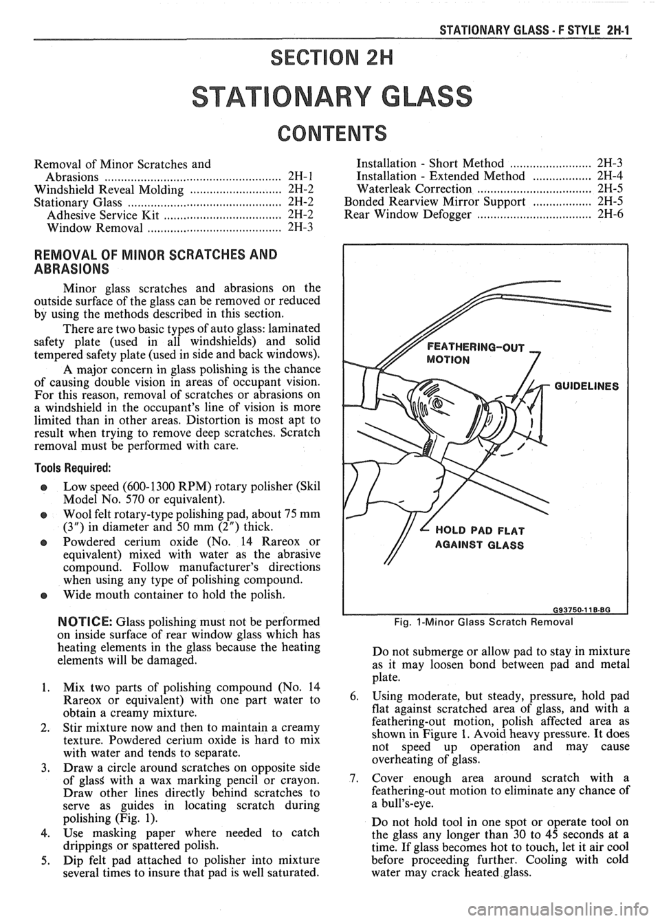
polishing (Fig. 1).
4. Use masking paper where needed to catch
drippings or spattered polish.
5. Dip felt pad attached to polisher into mixture
several times to insure that pad is well saturated.
FEATHERING-OUT
MOTION
GUIDELINES
// L HOLD PAD FLAT
Fig. I-Minor Glass Scratch Removal
Do not submerge or allow pad to stay in mixture
as it may loosen bond between pad and metal
plate.
6. Using moderate, but steady, pressure, hold pad
flat against scratched area of glass, and with a
feathering-out motion, polish affected area as
shown in Figure 1. Avoid heavy pressure. It does
not speed up operation and may cause
overheating of glass.
7. Cover enough area around scratch with a
feathering-out motion to eliminate any chance of
a bull's-eye.
Do not hold tool in one spot or operate tool on
the glass any longer than 30 to 45 seconds at a
time. If glass becomes hot to touch, let it air cool
before proceeding further. Cooling with cold
water may crack heated glass.