1988 PONTIAC FIERO remote start
[x] Cancel search: remote startPage 1466 of 1825
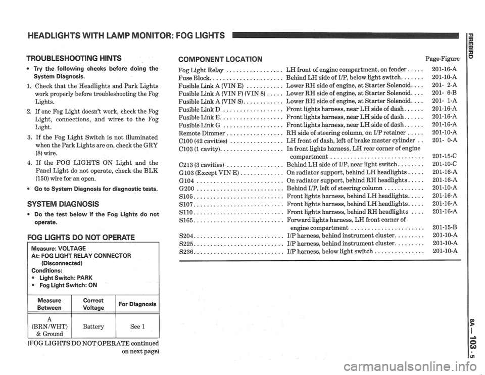
HEADLIGHTS WlTH LAMP MONITOR: FOG LIGHTS
TROUBLESHOOTING MINTS
0 Try the following checks before doing the
System Diagnosis.
1. Check that the Headlights and Park Lights
work properly before troubleshooting the Fog
Lights.
2. If one Fog Light doesn't work, check the Fog
Light, connections, and wires to the Fog
Light.
3. If the Fog Light Switch is not illu
when the Park Lights are on, check the
GRU
(8) wire.
4.
If the FOG LIGHTS ON Light and the
Panel Light do not operate, check the BLK
(150) wire for an open.
Go to System Diagnosis for diagnostic tests.
SYSTEM DIAGNOSIS
Do the test below if the Fog Lights do not
operate.
FOG LIGHTS DO NClT OPEWTE
Measure: VOLTAGE
At: FOG
LIGHT RELAY CONNECTOR
(Disconnected)
Conditions:
r Light Switch: PARK
Fog Light Switch:
ON
Measure Correct
For Diagnosis
Belvveen
COMPONENT LOCATION Page-Figure
................. Fog Light Relay LH front
of engine compartment, on fender. .... 201-16-A
..................... Fuse Block. Behind
LH side of IIP, below light switch. ...... 201-10-A
Fusible Link A (VIN
E) ........... Lower RN side of engine, at Starter Solenoid. ... 201- 2-A
Fusible Link A (VIN F) (VIN 8)
..... Lower RH side of engine, at Starter Solenoid. ... 201- 6-B
Fusible Link A (VIN S). ........... Lower RH side of engine, at Starter Solenoid. ... 201- 1-A
.................. Fusible Link D Front lights harness, near LH side of dash. ..... 201-16-A
.................. Fusible Link E. Front lights harness, near LH side of dash. ..... 201-16-A
.................. Fusible Link G Front
lights harness, near LK side of dash. ..... 201-16-A
................. Remote Dimmer RH side of steering column, on IIP retainer ..... 201-10-A
................ el00 (42 cavities) LH front
of dash, left of brake master cylinder .. 201- 0-A
.................. 6103 (1 cavity). In
front lights harness, LH rear corner of engine
.......................... compartment.. 201-15-C
................. 6213 (3 cavities) Behind LH side
of IIP, near light switch. ....... 201-10-C
6103 (Except VIN E) ............. On radiator support, behind LK headlights. .... 201-16-A
.......................... 6104 On radiator support, behind RH headlights. .... 201-16-A
.......................... ............ 6200 Behind IIP, left of steering column 201-10-A
.......................... S105. Front lights harness, behind LH headlights. .... 201-16-A
.......................... S107. Front lights harness, behind LH headlights. .... 201-16-A
.......................... S110. Front lights harness, behind RH headlights .... 201-16-A
S165. .......................... Forward lights harness, LH front comer of
...................... engine compartment 201-15-B
.......................... S204. I/P harness, behind instrument cluster. ........ 201-10-A
.......................... S225. I/P harness, behind instrument cluster. ........ 201-10-A
.......................... ............... S236. IIP harness, below light switch 201-10-A
(BRNIWNT)
& Ground
(FOG LIGHTS DO
NOT OPERATE continued
on next page)
Battery
See
1
Page 1674 of 1825
MISCELLANEOUS ACCESSORIES 96-4
SCELLANEOUS ACCESSOR
General Description ................................. 9G-1
Rally Gages .................................................. 9G- 1
Tachometer ................................................. 9G- 1
Trip Odometer
............................................. 9G- 1
Electric Rear Window Defogger ................. 9G-2
Power Remote Control Rearview
Mirror ........................................................ 9G-2
Diagnosis .................................................... 9G-2
Rally Gages ............................................... 9G-2
Tachometer .................................... .... .... 9G-2
Electric Rear Window Defogger ................. 9G-2
Power Remote Control Rearview
Mirror ........................................................ 96-2
Dash and Console Mounted
Accessory Switches
................................. 9G-4
General Description .................................. 9G-4
Electronic Glare Control Mirror ................. 9G-4
On-Car Service ............................................. 9G-4
Rally Gages, Tach ....................................... 96-4.
Rear Window Defogger ............................ 96-4.
Power Remote Control Mirror .................... 9G-4
GENERAL BESCRIP"T0N
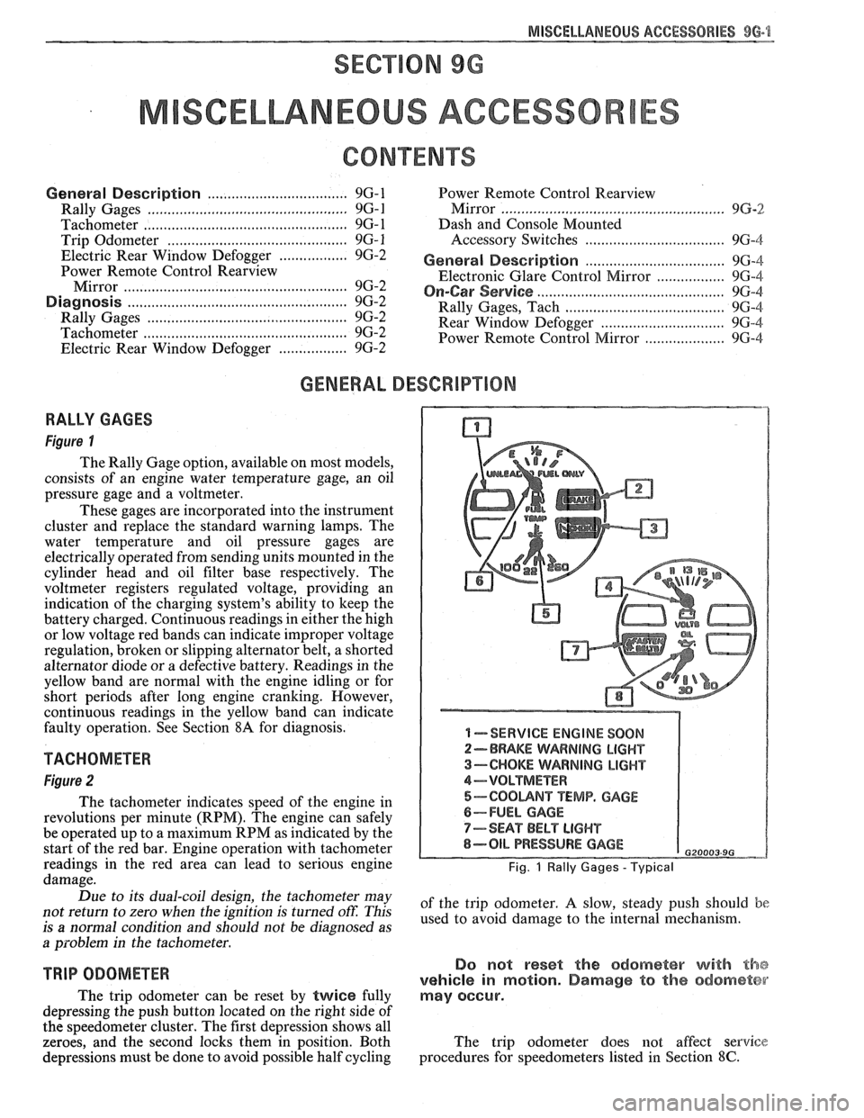
RALLY GAGES
Figure I
The Rally Gage option, available on most models,
consists of an engine water temperature gage, an oil
pressure gage and a voltmeter.
These gages are incorporated into the instrument
cluster and replace the standard warning lamps. The
water temperature and oil pressure gages are
electrically operated from sending units mounted in the
cylinder head and oil filter base respectively. The
voltmeter registers regulated voltage, providing an
indication of the charging system's ability to keep the
battery charged. Continuous readings in either the high
or low voltage red bands can indicate improper voltage
regulation, broken or slipping alternator belt,
a shorted
alternator diode
or a defective battery. Readings in the
yellow band are normal with the engine idling or for
short periods after long engine cranking. However,
continuous readings in the yellow band can indicate
faulty operation. See Section
8A for diagnosis.
TACHOMETER
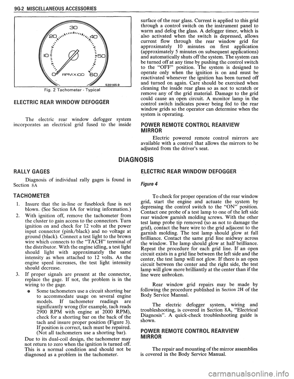
Figure 2
The tachometer indicates speed of the engine in
revolutions per minute (RPM). The engine can safely
be operated up to a maximum RPM as indicated by the
start of the red bar. Engine operation with tachometer
readings in the red area can lead to serious engine
damage.
Due to its dual-coil design, the tachometer may
not return to zero when the ignition
is turned oft: This
is
a normal condition and should not be diagnosed as
a problem in the tachometer.
TRIP ODOMETER
The trip odometer can be reset by twice fully
depressing the push button located on the right side of
the speedometer cluster. The first depression shows all
zeroes, and the second locks them in position. Both
depressions must be done to avoid possible half cycling
I -SERVICE ENGINE SOON
2-BRAKE WARNING LIGHT
3-CHOKE WARNING LIGHT
4-VOLTMETER
5-COOUNT TEMP. GAGE
6-FUEL GAGE
7-SEAT BELT LIGHT
8-OIL PRESSURE GAGE G20003 9G
Fig. 1 Rally Gages - Typical
of the trip odometer. A slow, steady push should be
used to avoid damage to the internal mechanism.
Do not reset the odometer with the
vehicle in motion. Damage to the odometer
may occur.
The trip odometer does not affect service
procedures for speedometers listed in Section
8C.
Page 1675 of 1825
9G-2 MISCELLANEOUS ACCESSORIES
Fig. 2 Tachometer - Typical
RPMX I00 €31-
ELECTRIC REAR WINDOW DEFOGGER
surface of the rear glass. Current is applied to this grid
through a control switch on the instrument panel to
warm and defog the glass. A defogger timer, which is
also activated when the switch is depressed, allows
current flow through the rear window grid
for
approximately 10 minutes on first application
(approximately
5 minutes on subsequent applications)
and automatically shuts off the system. The system can
be turned off at any time by pushing the control switch
to the "OFF" position. The system is designed to
operate only when the ignition is on and must be
reactivated whenever the ignition has been turned off
and turned on again. Care should be exercised when
cleaning the inside rear glass so as not to scratch or
remove any of the grid material. Damage to the grid
could cause an open circuit. A monitor lamp in-the
control switch indicates power being fed to the rear
window grids so the operator can determine when the
system is operating.
The electric rear window defogger system
incorporates an electrical grid fused to the inside
POWER REMOTE CONTROL REARVIEW
MIRROR
Electric powered remote control mirrors are
available with a control that allows the mirrors to be
adjusted from the driver's seat.
RALLY GAGES ELECTRIC REAR WINDOW DEFOGGER
Diagnosis of individual rally gages is found in
Section
8A Figure 4
TACHOMETER To check for moper o~eration of the rear window
1. Insure that the in-line or fuseblock fuse is not
blown. (See Section 8A for wiring information.)
2. With ignition off, remove the tachometer from
the cluster to gain access to the connectors. Turn
ignition on and check for
12 volts at the power
input connector
(pink/black) and no voltage at
ground (black). Connect a test light to the brown
wire which connects to the "TACH" terminal of
the distributor. With the engine idling, a test light
should light with approximately the same
intensity as when attached to
12 volts. As the
engine speed increases, the test light intensity
should decrease.
3. If proper signals are present at the connector,
replace the gage. If not, the problem is in the
wiring to the gage.
Some tachometers use a circuit shorting bar
to accommodate usage on several engine
models. If tachometer readings are
significantly wrong (for example, tach reads
2900 RPM with engine at 2000 RPM),
check for a shorting bar on the back of the
tach and insure proper position (Figure
3).
If position is correct, tach must be repaired.
(Not all tachometers use a shorting bar).
Due to its dual-coil design, the tachometer
may
- grid, start the engine a& actuate the system by
depressing the control switch to the
"ON" position.
Contact one probe of a test lamp to one of the left side
rear window garnish molding screws. With the other
test lamp probe tip removed (so as not to damage the
grid), contact the bare wire to the grid adjacent to the
garnish molding. The test lamp should glow at full
brilliance. Contact the same grid line midway across
the window. The lamp should glow at half brilliance.
Repeat the procedure for each grid line. If an open
circuit exists in a grid line between the left side and the
center, the test lamp will not glow. If there is an open
circuit between the center and the right side, the test
lamp will glow more brilliantly at the center than if the
line were unbroken.
Rear window grid repairs may be made by
following the procedure published in
Section 2H of the
Body Service Manual.
The electric defogger system, wiring and
troubleshooting, is covered in Section
8A, "Electrical
Diagnosis". A quick-check troubleshooting guide is
shown.
POWER REMOTE CONTROL REARVIEW
MIRROR
not return to zero when tvhe ignition is turned off'.
This is a normal condition and should not be The
repair and mounting of the mirror assemblies
diagnosed as a problem in the tachometer. is
covered in the Body Service Manual.
Page 1716 of 1825
BOORS - F STYLE 5H-3
I
J-9886
7
RETAINING SPRING
DISENGAGED 7
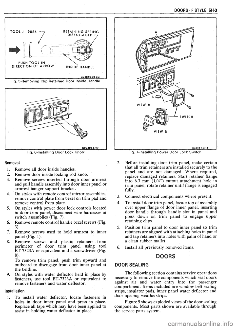
Fig. 5-Removing Clip Retained Door Inside Handle
Fig. 6-Installing Door Lock Knob
Removal
1. Remove all door inside handles.
2. Remove door inside locking rod knob.
3. Remove screws inserted through door armrest
and pull handle assembly into door inner panel or
armrest hanger support bracket.
4. On styles with remote control mirror assemblies,
remove control plate from bezel on trim pad and
remove control from plate.
5. On styles with power door lock controls located
in door trim panel, disconnect wire harnesses at
switch assemblies (Fig. 7).
6. Remove remote control handle bezel screws (Fig.
3)
7. Remove
screws used to hold armrest to inner
panel (Fig.
1).
8. Remove screws and plastic retainers from
perimeter of door trim panel using tool
BT-73238 or equivalent and a screwdriver (Fig.
8).
To remove trim panel, push trim upward and
outboard to disengage from door inner panel at
the beltline.
9. On styles with water deflector held in place by
fasteners, use tool BT-7323A or equivalent to
remove fasteners and water deflector.
Installation
1. To install water deflector, locate fasteners in
holes in door inner panel and press in place.
Replace all tape which may have been applied to
assist in holding water deflector in place.
Fig. 7-Installing Power Door Lock Switch
2. Before installing door trim panel, make certain
that all trim retainers are installed securely to the
panel and are not damaged. Where required,
replace damaged retainers. Start retainer Range
into 6.3 mm
(1/4") cutout attachment hole in
trim panel, rotate retainer until flange is engaged
fully.
3. Connect electrical components where present.
4. To install door trim panel, locate top of assembly
over upper flange of door inner panel, inserting
door handle through handle slot in panel and
press down on trim panel to engage upper
retaining clips.
5. Position trim panel to door inner panel so trim
retainers are aligned with attaching holes in panel
and tap retainers into holes with palm of hand or
a clean rubber mallet.
6. Install all previously removed items.
BOORS
DOOR SEALING
The following section contains service operations
necessary to remove the components which seal doors
against air and water entry into the passenger
compartment. Items included are window belt sealing
strips, insulator pads, inner panel water deflector and
door opening weatherstrips.
Figure
9 shows exploded views of the door sealing
components. Most parts shown are available through
the service parts system.
Page 1821 of 1825
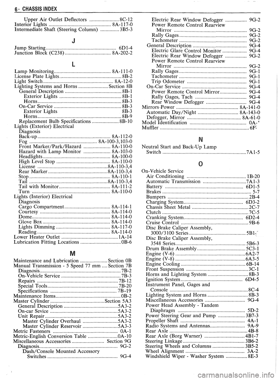
6- CHASSIS INDEX
Upper Air Outlet Deflectors ...................... 8C-12
Interior Lights ............................................. 8A- 1 17-0
Intermediate Shaft (Steering Column)
.............. 3B5-3
J
Jump Starting .................................................... 6D 1-4
Junction Block
((2238) ................................. 8A-202-2
L
Lamp Monitoring ......................................... 8A- 1 1 1-0
License Plate Lights .............................................. 8B-2
Light Switch
.................................................... 8A- 12-0
Lighting Systems and Horns
...................... Section 8B
General Description ......................................... .8 B- 1
Exterior Lights
............................................ 8B- 1
Horns ....................... .. ................................. 8B-3
On-Car Service
.................................................. 8B-3
Exterior Lights 8B-3
Horns
.............................................................. 8B-9
Replacement Bulb Specifications .................... 8B-10
Lights (Exterior) Electrical Diagnosis
Back-up
...................................................... 8A- 1 12-0
Fog ............................................... 8A- 100.3,10 3.0
Front
Marker/Park/Hazard .................... 8A-110-0
Hazard with Lamp Monitor .................... 8A-103-0
Headlights .................................................. 8A- 100-0
High Level Stop
..................................... 8A-110-0
License .................................................. .8A.110.3, 4
Rear Marker
........................................... .8 A. 1 10.3, 4
Stop ........................................................... 8A-110-1
Tail ......................................................... .8 A. 1 10.3, 4
Tail with Monitor
................ .... ........... 8A- 1 1 1-2
Turn
......................................................... 8A- 1 10-0
Lights (Interior) Electrical
Diagnosis Cargo Compartment
............................. 8A- 1 14- 1
Courtesy
................................................. 8A- 1 14-0
Dome
.................................. .. ...................... 8A- 1 14-0
Glove Box .................................................. 8A- 1 14-0
Lights Dimming
...................................... 8A- 1 17-0
Reading
...................................................... 8A- 1 14-0
Lower Heater Outlet
........................................ 1A-14
Lubrication Fitting Locations .............................. OB-6
M
Maintenance and Lubrication .................... Section OB
Manual Transmission
. 5 Speed 77 mm .... Section 7B
Diagnosis
........... .. ............................................ 7B-2
On-Vehicle Service
.......................................... 7B-3
Repairs
................................... .... .................... 7B- 12
Special Tools
................................................. 7B-20
. Specifications .............................................. 7B 19
Maintenance Items
................................................ OB-2
Master Cylinder
........................................ Section 5A3
General Description
...................................... ..5A 3.2
On-car Sevice
................................................ 5A3-2
Unit Repair ..................................................... .5A 3.2
Master Cylinder Overhaul
......................... .5A 3.2
Master Cylinder Reservoir
......................... .5A 3.3
Metric Fasteners
................................................ OA- 1
Metric-English Conversion Table ..................... .O A. 10
Miscellaneous Accessories
........................ Section 9G
Diagnosis
.......................................................... 9G-2
Dash/Console Mounted Accessory
Switches
.................................................... 9G-4 Electric
Rear Window Defogger
................ 9G-2
Power Remote Control
Rearview
......................... Mirror ...................... .. 9G-2
Rally Gages
................................................. 9G-2
Tachometer
.................................................. 9G-2
..................................... General Description 9G-4
Electric Glare Control Monitor
.................. 9G-4
Electric Rear Window Defogger
................ 9G-2
Power Remote Control
Rearview
Mirror ..................................................... 9G-2
Rally Gages
................................................. 9G-1
Tachometer
................................................. 9G-1
Trip Odometer
............................................ 9G-1
............................................. On-Car Service 9G-4
Power Remote Control Mirror
.................... 9G-4
Rally Gages. Tach
..................................... 9G-4
Rear Window Defogger
.............................. 9G-4
Mirrors..Power ............................................ 8A- 141-0
Automatic
Day/Night ............................. 8A- 143-0
..................................... Defogger. Mirror 8A-61-0
.......................................... Model Identification OA-'
Muffler ................................................................. 6Fi
N
Neutral Start and Back-Up Lamp
Switch
...................................... ..
0
On-Vehicle Service
Air Conditioning
.................................... ... . 1B-20
Automatic Transmission
............................... .7A 1.3
Battery
........................................................ 6D1-5
................................ ......................... Brakes ... 5-7
Bumpers
......................................................... 2B-4
Charging System
.............................. ... ........... 6D3-2
Chassis Sheet Metal
.......................................... 2C-7
Clutch
................................................................ 7C-5
Cranking System
............................................ 6D2-4
Cruise Control ............................................... 9B-6
Disc Brake Caliper Assembly,
3000/3 100 Series .......................................... 5BliC
Disc Brake Caliper Assembly,
3548 Series
................................................... 5B6-3
Drum Brake Assembly .................................... 5C3-1
Engine (V-6) .................................................... 6A2-7
Engine (V-8) ................................................ -6A3-5
Engine Cooling ....................................... .. .... 6B- 14
Front Suspension
........................................... 3C-1
Horns and Lighting System .............................. 8B-3
Ignition System
.............................................. 6D4-5
Instrument Panel, Gages and
Console
.......................................................... 8C-4
Lighting System and Horns
.......................... .... 8B-3
Miscellaneous Accessories
.......................... .... 9G-4
Power Head Assembly
. Tandem
Diaphragm
................................................. 5D-2
Power Steering Gear and Pump
.................... 3B7-3
Propeller Shaft
............................................. 4A-1
.......................... Radio Systems and Antennas 9A-9
Rear Axle
.......................................................... 4B-8
Rear Axle (Borg Warner)
........................... ... 4B 1-7
Steering Linkage ............................................. 3B6-2
........................ Steering Wheels and Columns 3B5-2
Wheel Alignment
......................................... 3A-2
Windshield Wiper
- Washer System ................ 8E-3
Page 1823 of 1825
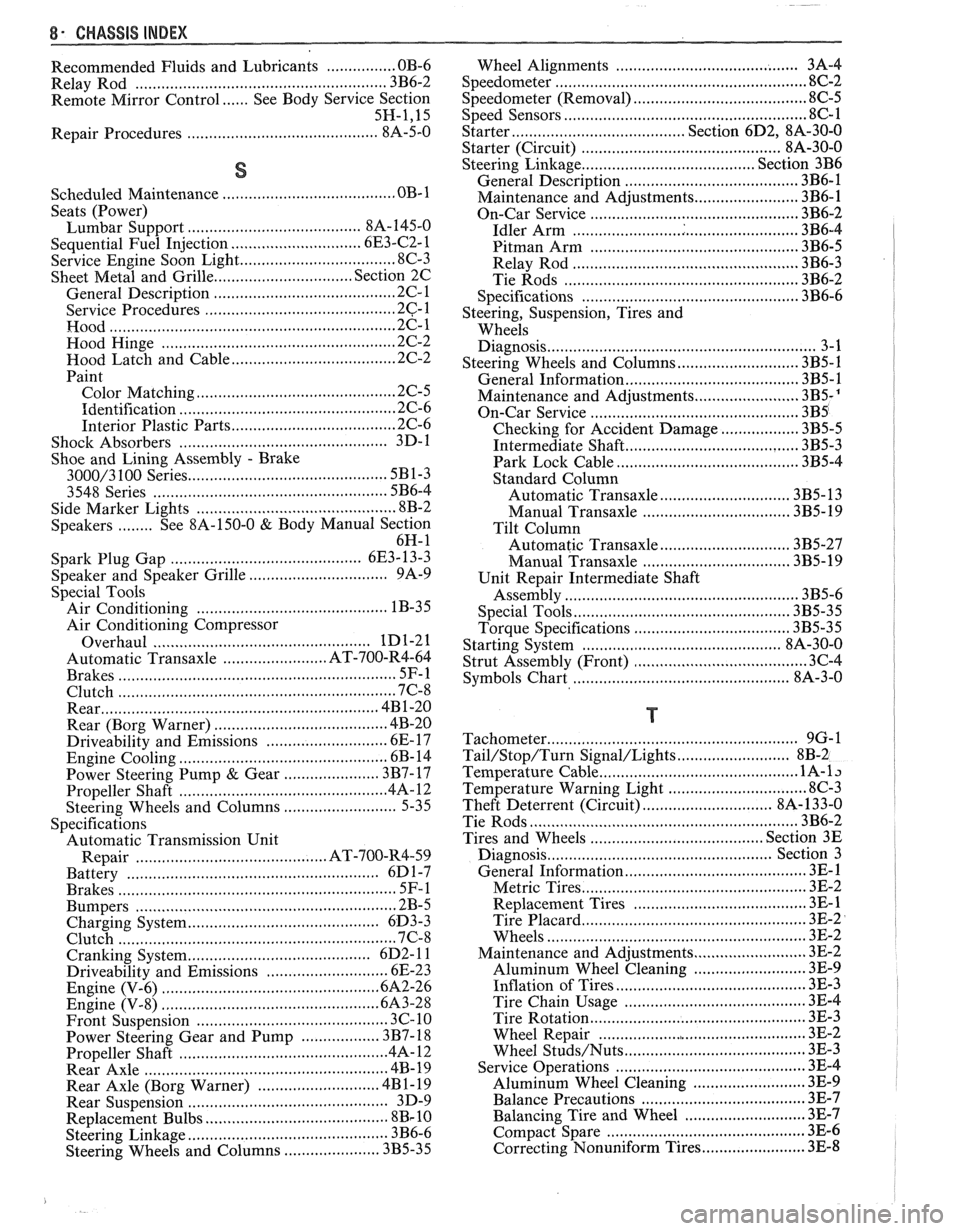
8- CHASSIS INDEX
Recommended Fluids and Lubricants ................ OB-6
Relay Rod
......................................................... 3B6-2
Remote Mirror Control
...... See Body Service Section
5H.1. 15
Repair Procedures
.......................................... 88-50
S
........................................ Scheduled Maintenance OB- 1
Seats (Power) ....................................... Lumbar Support 8A- 145-0
............................. Sequential Fuel Injection 6E3-C2- 1
Service Engine Soon Light
.................................... 8C-3
Sheet Metal and Grille
................................ Section 2C
......................................... General Description .2 C. 1
........................................... Service Procedures .2 C. 1
................................................................. Hood .2 C. 1
...................................................... Hood Hinge 2C-2
Hood Latch and Cable
...................................... 2C-2
Paint
.............................................. Color Matching 2C-5
................................................ Identification -32-6
Interior Plastic Parts ...................................... 2C-6
................................................ Shock Absorbers 3D-
1
Shoe and Lining Assembly
. Brake
............................................ 3000/3 100 Series 5B1-3
3548 Series ...................................................... 5B6-4
Side Marker Lights
.............................................. 8B-2
........ Speakers See 8A- 150-0 & Body
Manual Section
6H- 1
.................... Spark Plug Gap .. .................. 6E3-13-3
................................ Speaker and Speaker Grille 9A-9
Special Tools
............................................ Air Conditioning 1 B-3 5
Air Conditioning Compressor
................................................. Overhaul 1D1-21
........................ Automatic Transaxle AT-700-R4-64
................................................................ Brakes SF-1
Clutch ................................................................ 7C-8
................................................................ Rear 4B1-20
....................................... Rear (Borg Warner) 4B-20
........................... Driveability and Emissions .6 E. 17
................................................ Engine Cooling 6B- 14
Power Steering Pump
& Gear ...................... 3B7-17
............................................... Propeller Shaft .4 A. 12
Steering Wheels and Columns
.......................... 5-35
Specifications Automatic Transmission Unit
............................................ Repair AT-700-R4-59
..................................................... Battery 6D 1-7
................................................................ Brakes 5F-1
Bumpers
......................................................... 2B-5
Charging System
................ .. ................... 6D3-3
.............................................................. Clutch .7 (2.8
....................................... Cranking System 6D2- 1 1
Driveability and Emissions ............................ 6E-23
................................................ Engine (V-6) ..6A 2.26
Engine (V-8) .................................................. 683-28
........................................ Front Suspension 3C- 10
Power Steering Gear and Pump
.................. 3B7-18 ............................................. Propeller Shaft .4 A. 12 ........................................................ Rear Axle 4B-19 ............................ Rear Axle (Borg Warner) 4B 1- 19
Rear Suspension
.............................................. 3D-9
.......................................... Replacement Bulbs 8Br 10 .............................................. Steering Linkage 3B6-6
Steering Wheels and Columns
...................... 3B5-35
........................................ Wheel Alignments 3A-4
....................................................... Speedometer 8C-2
........................................ Speedometer (Removal) 8C-5
...................................................... Speed Sensors 8C-1
Starter ........................................ Section 6D2. 8A-30-0
............................................. Starter (Circuit) 8A-30-0
Steering Linkage ...................................... Section 3B6
....................................... General Description 3B6-1
........................ Maintenance and Adjustments 3B6-1
................................................ On-Car Service 3B6-2
..................................................... Idler Arm 3B6-4
................................................ Pitman Arm 3B6-5
.................................................... Relay Rod 3B6-3
Tie Rods
...................................................... 3B6-2
.................................................. Specifications 3B6-6
Steering, Suspension, Tires and
Wheels Diagnosis
............................................................. 3-1
Steering Wheels and Columns
............................ 3B5-1
..................................... General Information 3B5- 1
Maintenance and Adjustments
...................... 3B5-'
On-Car Service .............................. .. ........... 3B5
Checking for Accident Damage
.................. 3B5-5
Intermediate Shaft ............... .. .................... 3B5-3
Park Lock Cable .......................................... 3B5-4
Standard Column
............................. Automatic Transaxle 3B5-13
Manual Transaxle ................................. 3B5- 19
Tilt Column
.............................. Automatic Transaxle 3B5-27
.................................. Manual Transaxle 3B5-19
Unit Repair Intermediate Shaft
...................................................... Assembly 3B5-6
................................................. Special Tools 3B5-35
Torque Specifications
.................................... 3B5-35
............................................. Starting System 8A-30-0
........................................ Strut Assembly (Front) 3C-4
.................................... ..... Symbols Chart ... 8A-3-0
T
.......................................................... Tachometer 9G-1
Tail/Stop/Turn Signal/Lights .......................... 8B-2
Temperature Cable
.............................................. 112 A-
Temperature Warning Light ................................ 8C-3
Theft Deterrent (Circuit)
.............................. 8A-133-0
Tie Rods
.............................................................. 3B6-2
Tires and Wheels
........................................ Section 3E
Diagnosis
.................................................. Section 3
General Information
......................................... 3E-1
................................................... Metric Tires 3E-2
....................................... Replacement Tires .31 E-
.................................................... Tire Placard 3E-2
........................................................... Wheels 3E-2
Maintenance and Adjustments
.......................... 3E-2
.......................... Aluminum Wheel Cleaning 3E-9
............................. ......... Inflation of Tires .. 3E-3
........................................ Tire Chain Usage 3E-4
.................................................. Tire Rotation 3E-3
.............................................. Wheel Repair 3E-2
...................................... Wheel Studs/Nuts 3E-3
........................................... Service Operations 3E-4
........................ Aluminum Wheel Cleaning 3E-9
.................................... Balance Precautions 3E-7
............................ Balancing Tire and Wheel 3E-7
.............................................. Compact Spare 3E-6
........................ Correcting Nonuniform Tires 3E-8