1988 PONTIAC FIERO weight
[x] Cancel search: weightPage 1003 of 1825
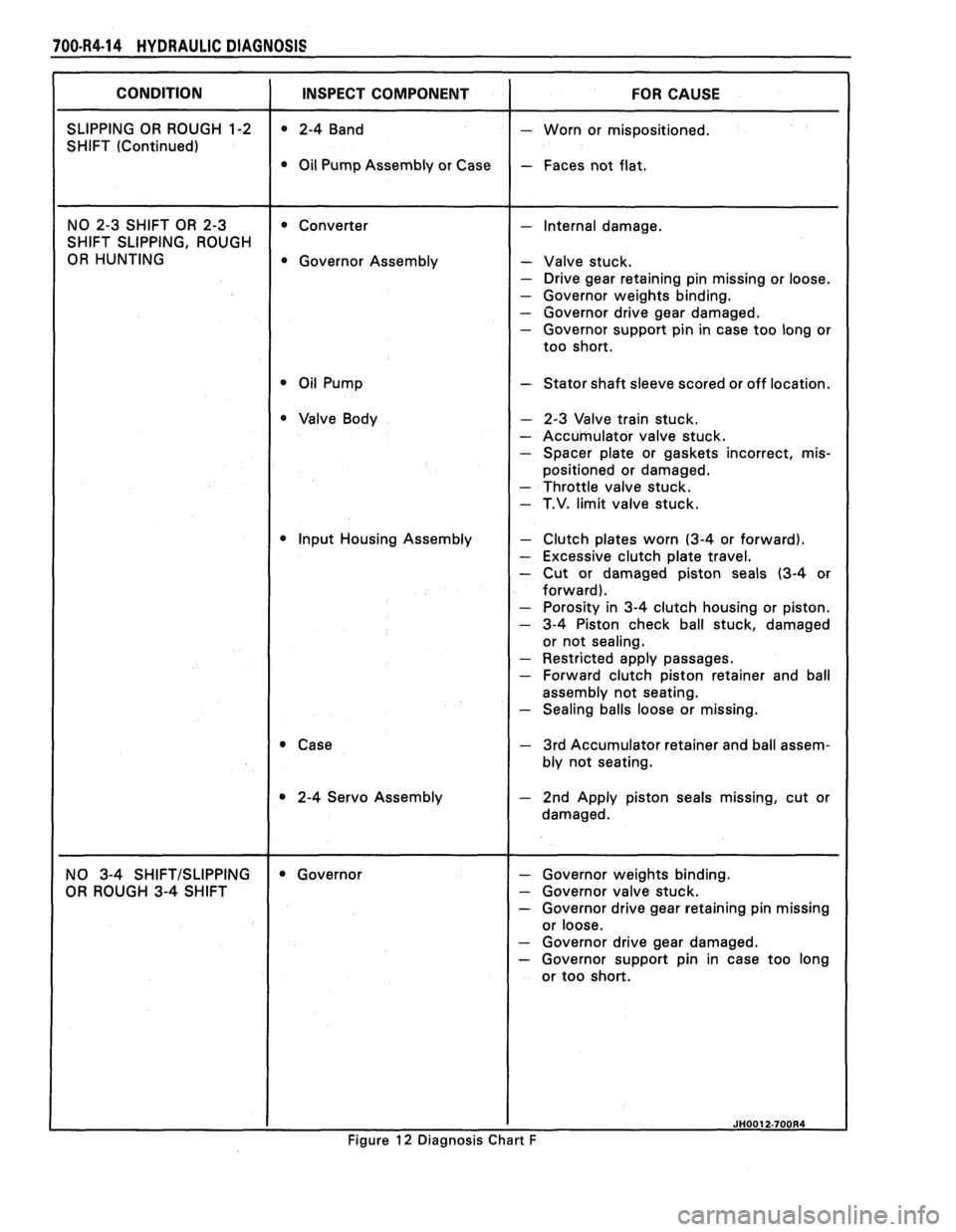
700-R4-14 HYDRAULIC DIAGNOSIS
SHIFT SLIPPING, ROUGH
OR HUNTING Governor Assembly - Valve stuck.
- Drive gear retaining pin missing or loose.
- Governor weights binding.
- Governor drive gear damaged. - Governor support pin in case too long or
- Stator shaft sleeve scored or off location.
- 2-3 Valve train stuck.
- Accumulator valve stuck. - Spacer plate or gaskets incorrect, mis-
positioned or damaged.
- Throttle valve stuck.
- T.V. limit valve stuck.
Input Housing Assembly
- Clutch plates worn (3-4 or forward).
- Excessive clutch plate travel.
- Cut or damaged piston seals (3-4 or
- Restricted apply passages. - Forward clutch piston retainer and ball
assembly not seating.
- Sealing balls loose or missing.
- 3rd Accumulator retainer and ball assem-
bly not seating.
2-4 Servo Assembly
OR ROUGH 3-4 SHIFT
- Governor valve stuck. - Governor drive gear retaining pin missing
- Governor drive gear damaged. - Governor support pin in case too long
or too short.
Figure
12 Diagnosis Chart F
Page 1005 of 1825
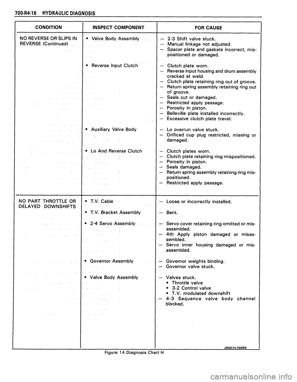
700-R4-16 HYDRAULIC DIAGNOSIS
I CONDITION I INSPECT COMPONENT I FOR CAUSE
NO REVERSE OR SLIPS IN
REVERSE (Continued) Valve
Body Assembly
Reverse Input Clutch
Auxiliary Valve Body
1 Lo And Reverse Clutch
- 2-3 Shift valve stuck.
- Manual linkage not adjusted.
- Spacer plate and gaskets incorrect, mis-
positioned or damaged.
Clutch plate worn.
Reverse input housing and drum assembly
cracked at weld.
Clutch plate retaining ring out of groove.
Return spring assembly retaining ring out
of groove.
Seals cut or damaged.
Restricted apply passage.
Porosity in piston.
Belleville plate installed incorrectly.
Excessive clutch plate travel.
- Lo overrun valve stuck. - Orificed cup plug restricted, missing or
damaged.
- Clutch plates worn. - Clutch plate retaining ring mispositioned.
- Porosity in piston.
- Seals damaged. - Return spring assembly retaining ring mis-
positioned.
- Restricted apply passage.
NO PART THROTTLE OR
DELAYED DOWNSHIFTS T.V.
Cable
T.V. Bracket Assembly
2-4 Servo Assembly
Governor Assembly
Valve Body Assembly
I
- Loose or incorrectly installed.
- Bent.
- Servo cover retaining ring omitted or mis-
assembled.
- 4th Apply piston damaged or misas-
sembled. - Servo inner housing damaged or mis-
assembled.
- Governor weights binding.
- Governor valve stuck.
- Valves stuck.
Throttle valve
3-2 Control valve
T.V. modulated downshift
- 4-3 Sequence valve body channel
blocked.
I I JH0014-700R4
Figure 14 Diagnosis Chart H
Page 1054 of 1825
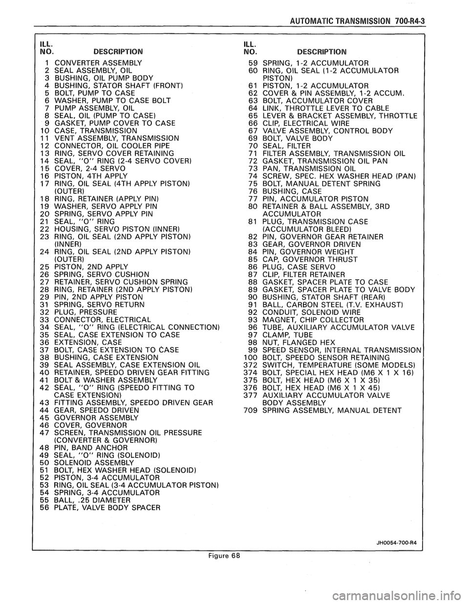
AUTOMAT lC TRANSMISSION 700-R4-3
ILL. NO. DESCRIPTION
1 CONVERTER ASSEMBLY
2 SEAL ASSEMBLY, OIL
3 BUSHING, OIL PUMP BODY
4 BUSHING, STATOR SHAFT (FRONT)
5 BOLT, PUMP TO CASE
6 WASHER, PUMP TO CASE BOLT
7 PUMP ASSEMBLY, OIL
8 SEAL, OIL (PUMP TO CASE)
9 GASKET, PUMP COVER TO CASE
10 CASE, TRANSMISSION
11 VENT ASSEMBLY, TRANSMISSION
1 12 CONNECTOR, OIL COOLER PIPE 13 RING, SERVO COVER RETAINING
14 SEAL, "0" RlNG
(2-4 SERVO COVER)
15 COVER, 2-4 SERVO
16 PISTON, 4TH APPLY
17 RING, OIL SEAL
(4TH APPLY PISTON)
(OUTER)
18 RING, RETAINER (APPLY PIN)
19 WASHER, SERVO APPLY PIN
20 SPRING, SERVO APPLY PIN
21 SEAL,
"0" RlNG
22 HOUSING, SERVO PISTON (INNER)
23 RING, OIL SEAL
(2ND APPLY PISTON)
(INNER)
24 RING, OIL SEAL
(2ND APPLY PISTON)
(OUTER)
25 PISTON, 2ND APPLY
26 SPRING, SERVO CUSHION
27 RETAINER, SERVO CUSHION SPRING
28 RING, RETAINER
(2ND APPLY PISTON)
29 PIN, 2ND APPLY PISTON
31 SPRING, SERVO RETURN
32 PLUG, PRESSURE
33 CONNECTOR, ELECTRICAL
34 SEAL,
"0" RlNG (ELECTRICAL CONNECTION)
35 SEAL, CASE EXTENSION TO CASE
36 EXTENSION, CASE
37 BOLT, CASE EXTENSION TO
CASE 38 BUSHING, CASE EXTENSION
39 SEAL ASSEMBLY, CASE EXTENSION OIL
40 RETAINER, SPEEDO DRIVEN GEAR FITTING
41 BOLT
& WASHER ASSEMBLY
42 SEAL, "0" RlNG (SPEEDO FITTING TO
CASE EXTENSION)
43 FITTING ASSEMBLY, SPEEDO DRIVEN GEAR
44 GEAR, SPEEDO DRIVEN
45 GOVERNOR ASSEMBLY
46 COVER, GOVERNOR
47 SCREEN, TRANSMISSION OIL PRESSURE
(CONVERTER
81 GOVERNOR)
48 PIN, BAND ANCHOR
49 SEAL,
"0" RlNG (SOLENOID)
50 SOLENOID ASSEMBLY
51 BOLT, HEX WASHER HEAD (SOLENOID)
52 PISTON, 3-4 ACCUMULATOR
53 RING, OIL SEAL
(3-4 ACCUMULATOR PISTON)
54 SPRING, 3-4 ACCUMULATOR
55 BALL,
.25 DIAMETER 56 PLATE, VALVE BODY SPACER
ILL. NO. DESCRIPTION
59 SPRING, 1-2 ACCUMULATOR
60 RING, OIL SEAL (1
-2 ACCUMULATOR
PISTON)
61 PISTON, 1-2 ACCUMULATOR
62 COVER
& PIN ASSEMBLY, 1-2 ACCUM.
63 BOLT, ACCUMULATOR COVER
64 LINK, THROTTLE LEVER TO CABLE
65 LEVER
& BRACKET ASSEMBLY, THROTTLE
66 CLIP, ELECTRICAL WIRE
67 VALVE ASSEMBLY, CONTROL BODY
69 BOLT, VALVE BODY
70 SEAL, FILTER
71 FILTER ASSEMBLY, TRANSMISSION OIL
72 GASKET, TRANSMISSION OIL PAN
73 PAN, TRANSMISSION OIL
74 SCREW, SPEC. HEX WASHER HEAD (PAN)
75 BOLT, MANUAL DETENT SPRING
76 BUSHING, CASE
77 PIN, ACCUMULATOR PISTON
80 RETAINER
& BALL ASSEMBLY, 3RD
ACCUMULATOR
81 PLUG, TRANSMISSION CASE
(ACCUMULATOR BLEED)
82 PIN, GOVERNOR GEAR RETAINER
83 GEAR, GOVERNOR DRIVEN
84 PIN, GOVERNOR WEIGHT
85 CAP, GOVERNOR THRUST
86 PLUG, CASE SERVO
87 CLIP, FILTER RETAINER
88 GASKET, SPACER PLATE TO CASE
89 GASKET, SPACER PLATE TO VALVE BODY
90 BUSHING, STATOR SHAFT
(REAR)
91 BALL, CARBON STEEL (T.V. EXHAUST)
92 CONDUIT, SOLENOID WIRE
93 MAGNET, CHIP COLLECTOR
96 TUBE, AUXILIARY ACCUMULATOR VALVE
97 CLAMP, TUBE
98 NUT, FLANGED HEX
99 SPEED SENSOR, INTERNAL
TRANSMISSIOr 100 BOLT, SPEEDO SENSOR RETAINING
372 SWITCH, TEMPERATURE (SOME MODELS)
374 BOLT, SPECIAL HEX HEAD (M6 X
1 X 16)
375 BOLT, HEX HEAD (M6 X 1 X
35) 376 BOLT, HEX HEAD (M6 X 1 X 45)
377 AUXILIARY ACCUMULATOR VALVE
BODY ASSEMBLY
709 SPRING ASSEMBLY, MANUAL DETENT
Figure 68
Page 1103 of 1825
700-R4-52 AUTOMATIC TRANSMISSION
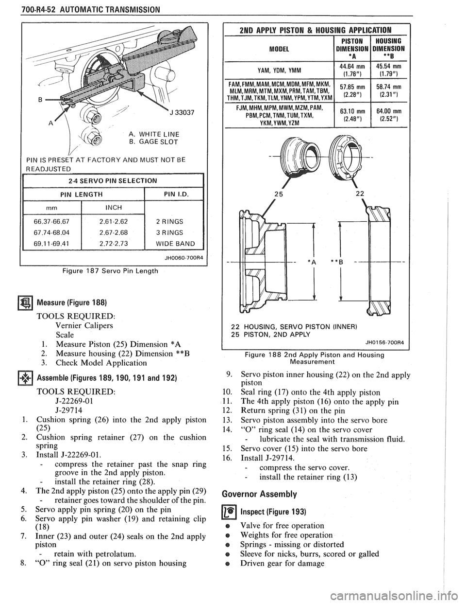
A. WHITE LINE B. GAGE SLOT
Figure 187 Servo Pin Length
Measure (Figure 188)
TOOLS REQUIRED:
Vernier Calipers
Scale
1. Measure Piston (25) Dimension
*A
2.
Measure housing (22) Dimension **B
3. Check Model Application
Assemble (Figures 189, 190, 191 and 192)
TOOLS REQUIRED:
5-22269-01
J-297 14
1. Cushion spring (26) into the 2nd apply piston
(25)
2. Cushion spring retainer (27) on the cushion
spring
3. Install J-22269-01.
- compress the retainer past the snap ring
groove in the 2nd apply piston.
- install the retainer ring (28).
4. The 2nd apply piston (25) onto the apply pin (29)
- retainer goes toward the shoulder of the pin.
5. Servo apply pin spring (20) on the pin
6. Servo apply pin washer (19) and retaining clip
(18)
7. Inner (23) and outer (24) seals on the 2nd apply
piston
- retain with petrolatum.
8. "0" ring seal (21) on servo piston housing
2ND APPLY PISTON & HOUSING APPLICATION
MODEL I DIMt!SION DIMENSION I **B I
I YAM, YOM, YMM I
MLM, MRM,MTM,MXM, PRM,TAM,TBM,
22 HOUSING, SERVO PISTON (INNER)
25 PISTON, 2ND APPLY
JH0156-700R4
Figure 188 2nd Apply Piston and Housing
Measurement
9. Servo piston inner housing (22) on the 2nd apply
piston
10. Seal ring (17) onto the 4th apply piston
11. The 4th apply piston (16) onto the apply pin
12. Return spring (31) on the pin
13. Servo piston assembly into the servo bore
14.
"0" ring seal (14) on the servo cover
- lubricate the seal with transmission fluid.
15. Servo cover (15) into the servo bore
16. Install J-297 14.
- compress the servo cover.
- install the retainer ring (13)
Governor Assembly
Inspect (Figure 193)
e Valve for free operation
e Weights for free operation
e Springs - missing or distorted
Sleeve for nicks, burrs, scored or galled
o Driven gear for damage
Page 1104 of 1825
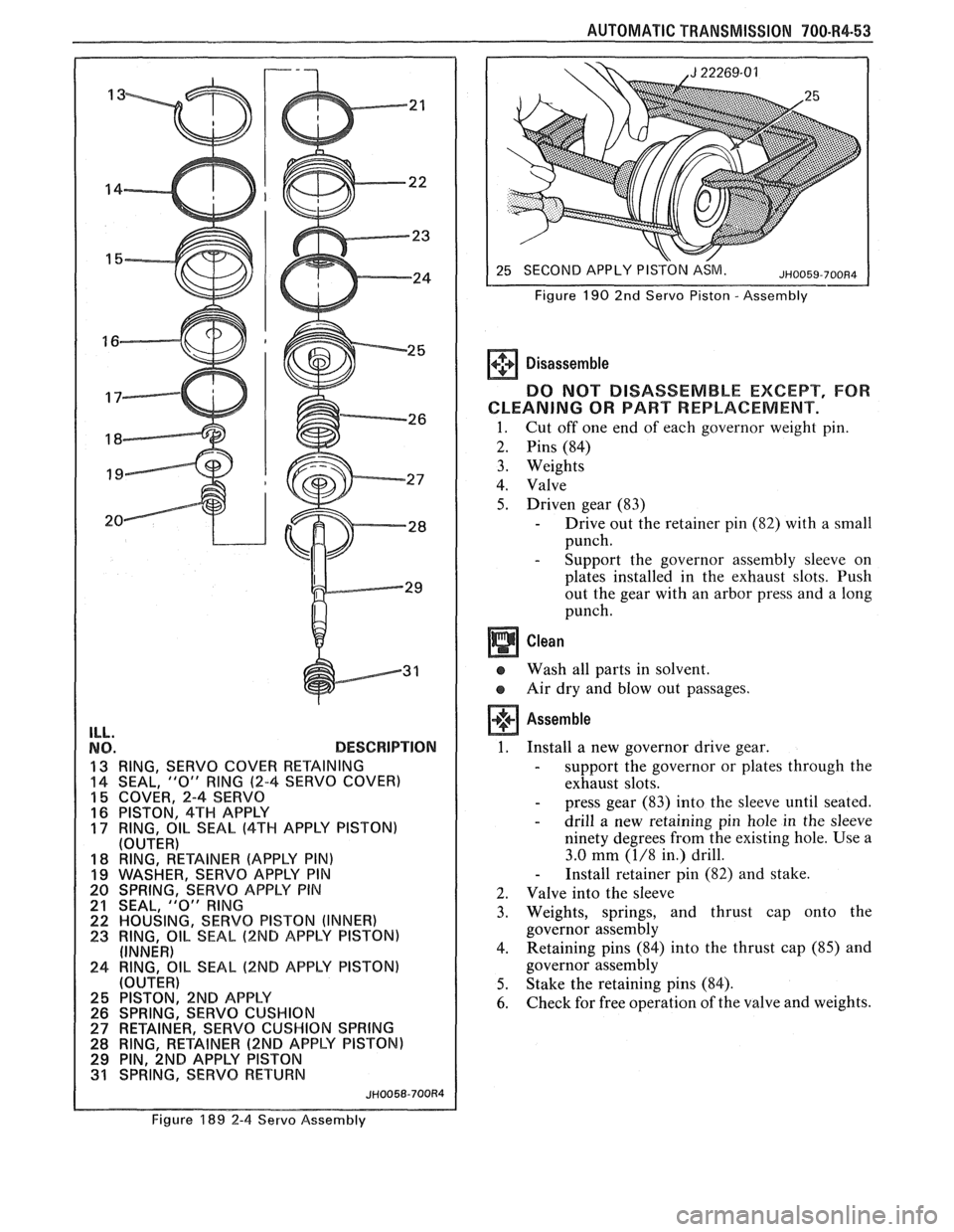
ILL.
NO. DESCRlPTlON
13 RING, SERVO COVER RETAINING
14 SEAL, "0" RlNG (2-4 SERVO COVER)
15 COVER, 2-4 SERVO
16 PISTON. 4TH APPLY
17 RING, 811- SEAL (4TH APPLY PISTON)
(OUTER)
18 RING, RETAINER (APPLY PIN) 19 WASHER, SEWVO APPLY PIN
20 SPRING, SERVO APPLY PIN
21 SEAL, "0" RlNG 22 HOUSING, SERVO PISTON (INNER)
23 RING, OIL SEAL (2ND APPLY PISTON)
(INNER)
24 RING, OIL SEAL (2ND APPLY PISTON)
(OUTER)
29 PIN, ~NB APPLY PISTON
31 SPRING, SERVO RETURN
JH0058-700R4
AUTOMATIC TRANSMISSION 700-R4-53
SECOND APPLY PISTON ASM.
Figure
190 2nd Servo Piston - Assembly
Disassemble
DO NOT DISASSEMBLE EXCEPT, FOR
CLEANING
OR PART REPLACEMENT.
1. Cut off one end of each governor weight pin.
2. Pins (84)
3. Weights
4. Valve
5. Driven gear (83)
- Drive out the retainer pin (82) with a small
punch.
- Support the governor assembly sleeve on
plates installed in the exhaust slots. Push
out the gear with an arbor press and a long
punch.
e Wash all parts in solvent.
Air dry and blow out passages.
Assemble
1. Install a new governor drive gear.
- support the governor or plates through the
exhaust slots.
- press gear (83) into the sleeve until seated.
- drill a new retaining pin hole in the sleeve
ninety degrees from the existing hole. Use a
3.0
mm (1/8 in.) drill.
- Install retainer pin (82) and stake.
2. Valve into the sleeve
3. Weights, springs, and thrust cap onto the
governor assembly
4. Retaining
pins (84) into the thrust cap (85) and
governor assembly
5. Stake the retaining pins (84).
6. Check for free operation of the valve and weights.
Figure 189 2-4 Servo Assembly
Page 1105 of 1825
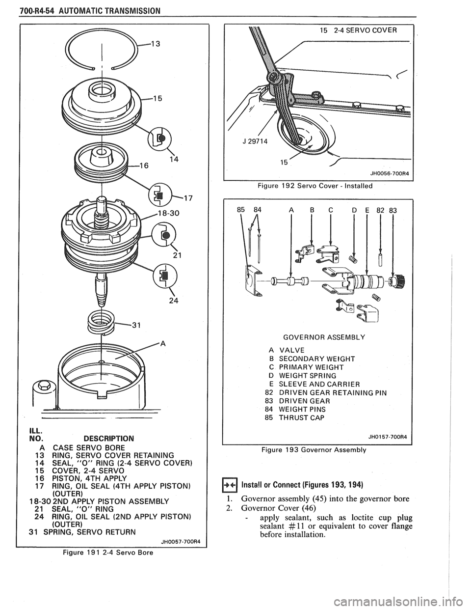
700-R4-54 AUTOMATIC TRANSMISSION
ILL.
NO. DESCRlPTlON
A CASE SERVO BORE
13 RING, SERVO COVER RETAINING
14 SEAL,
"0" RING (2-4 SERVO COVER)
15 COVER, 2-4 SERVO
16 PISTON, 4TH APPLY 17 RING, OIL SEAL (4TH APPLY PISTON)
(OUTER)
18-30 2ND APPLY PISTON ASSEMBLY
21 SEAL.
"0" RlNG
24 RING,' OIL SEAL (2ND APPLY PISTON) (OUTER)
31 SPRINGT~~ERVO RETURN
JH0057-700R4
Figure 19 1 2-4 Servo Bore Figure
192 Servo
Cover - Installed
GOVERNOR ASSEMBLY
A VALVE
B SECONDARY WEIGHT
C PRIMARY WEIGHT
D WEIGHT SPRING
E SLEEVE AND CARRIER
82 DRIVEN GEAR RETAINING PIN
83 DRIVEN GEAR
84 WEIGHT PINS
85 THRUST CAP
Figure 193 Governor Assembly
Install or Connect (Figures 193, 194)
1. Governor assembly (45) into the governor bore
2. Governor Cover (46)
- apply sealant, such as loctite cup plug
sealant
# 11 or equivalent to cover flange
before installation.
Page 1118 of 1825
AUTOMATIC TRANSMISSION 7A-3
PRELIMARY CHECKING PROCEDURE
The condition of an automatic transmission not
operating properly may be influenced by one, or a
combination of the following items:
e Fluid level high/low
(Refer to Section 7A1)
e Engine performance
(Refer to Sections 6 and 6E)
T.V. cable adjustment
(Refer to Section
7A1)
e Manual linkage adjustment
(Refer to Section
7A1)
e Internal fluid leaks
(Refer to Transmission Unit Repair section)
e Electrical system
(Refer to Section 6E and 8A)
e Transmission or other mechanical component
(Refer to Transmission Unit Repair section)
e Vacuum modulator
(Refer to appropriate Hydraulic Diagnosis
Section)
NOISE AND VIBRATION ANALYSIS
A noise or vibration that is noticeable when the
vehicle is in motion, MAY NOT be the result of the
transmission.
If noise or vibration is noticeable in "Park"
(P)
and "Neutral" (N) with engine at idle, but is less
noticeable as
RPM's increase, the cause may be from
poor engine performance.
e Tires for
- Uneven wear
- Imbalance
- Mixed sizes
- Mixed radial and bias ply
(Refer to Section 3E)
e Suspension components for
- Alignment and wear
- Loose fasteners
(Refer to Section 3C)
e Engine/Transmission mounts for
- Damage
- Loose bolts
(Refer
to Sections 6A and 7A2)
e Transmission case mounting holes for:
- Missing bolts, nuts, studs
- Stripped threads
- Cracks
e Flywheel for:
- Missing or loose bolts
- Cracks
- Imbalance
(Refer to Section 6A)
e Torque converter for: - Missing or loose bolts or lugs - Missing or loose balance weights
- Imbalance
TRANSMISSION FLUID LEVEL INFORMATION
Checking fluid level, color and condition at
regular intervals will provide early diagnosis
information about the transmission. This information
may then be used to correct a condition that, if not
detected early, could result in major transmission
repairs.
When adding or changing fluid, use only
DEXRONO 11, or equivalent. Refer to Section OB of
this Service Manual for maintenance information and
servicing intervals.
Fluid level should be checked when it reaches
normal operating temperatures of
190-200°F.
(88-93°C). This temperature is reached after
approximately 15 miles (24 km) of highway
driving.
e Fluid color - Should be dark red (may be dark green)
NOTICE: Do not overfill. Overfilling will cause
foaming, loss of fluid and possible damage to the
transmission.
Inaccurate fluid level readings will result if
checked immediately after the vehicle has been
operated:
- In high abmient temperatures above 90°F
(32°C)
- At sustained high speeds
- In heavy city traffic during hot weather
- As a towing vehicle - In commercial service (taxi or police use)
TRANSMISSION FLUID CHECKING
PROCEDURE
(Refer to Figure 3)
1. Park vehicle on level ground.
2. Apply parking
brake and block wheels.
3. Start
engine and operate vehicle for 15 minutes or
until a normal operating temperature is reached.
4. Move gear
selector through all gear positions.
5. Move
gear selector to "Park" (P).
6. Check fluid level, color and condition.
Page 1153 of 1825
78-16 BSPEED 77MM TMNSMISSION
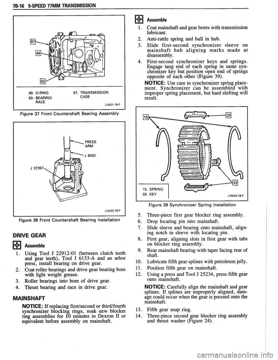
49. O-RING 67. TRANSMISSION
50. BEARING CASE
Figure 37 Front Countershaft Bearing Assembly
Figure
38 Front Countershaft Bearing Installation
DRIVE GEAR
Assemble
1. Using Tool J 22912-01 (between clutch teeth
and gear teeth), Tool
J 6133-A and an arbor
press, install bearing on drive gear.
2. Coat roller bearings and drive gear bearing bore
with light weight grease.
3. Roller bearings into bore of drive gear.
4. Thrust bearing and race in drive gear.
MAINSHAm
NOTICE: If replacing firstfsecond or thirdlfourth
synchronizer blocking rings, soak new blocker
ring assemblies for 10 minutes in Dexron
I1 or
equivalent before assembly on mainshaft.
Assemble
1. Coat mainshaft and
gear bores with transmission
lubricant.
2. Anti-rattle
spring and ball in hub.
3. Slide first-second synchronizer sleeve on
mainshaft hub aligning marks made at
disassembly.
4. First-second synchronizer keys and springs.
Engage tang end of each spring in same syn-
chronizer key but position open end of springs
opposite of each other (Figure 39).
NOTICE: Use care in synchronizer spring place-
ment. Synchronizer can be assembled with
improper spring placement, but hard shifting will
result.
Figure 39 Synchronizer Spring Installation
5. Three-piece first gear blocker ring assembly.
6. Drop locating pin into mainshaft.
7. Slide sleeve and bearing onto mainshaft, align-
ing notch in sleeve with locating pin.
8. First gear, aligning slots in first gear with tabs
on blocker ring assembly.
9. Rear
mainshaft bearing with taper facing rear of
shaft.
10. Lubricate fifth gear splines with petroleum jelly.
1 1. Position fifth gear on mainshaft.
12. Using a press and Tool
J 25234, press fifth gear
onto mainshaft.
NOTICE: Carefully align the mainshaft and gear
splines. If splines are improperly aligned, dam-
age could occur when the gear is pressed onto the
mainshaft.
13. Fifth gear snap ring.
14. Three-piece
second gear blocker ring assembly
and thrust washer (Figure 24).