1988 PONTIAC FIERO heater
[x] Cancel search: heaterPage 65 of 1825
1B-22 AIR CONDITIONING
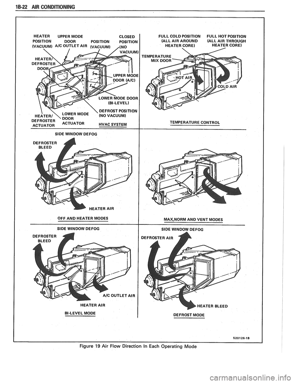
HEATER UPPER MODE CLOSED
POSITION DOOR POSITION POSITION
I SIDE WINDOW DEFOG
DEFROSTER
A BLEED
HEATER AIR
OFF AND HEATER MODES
SlDE WINDOW DEFOG
HEATER AIR
BI-LEVEL MODE FULL
COLD POSITION
FULL HOT POSITION
(ALL AIR AROUND
(ALL AIR THROUGH
HEATER CORE) HEATER CORE)
TEMPERATURE
TEMPERATURE
COlUTROL
MAX,NORM AND VENT MODES
SlDE WINDOW DEFOG
DEFROSTER AIR
HEATER BLEED
DEFROST MODE
5201 26-1 8
Figure 19 Air Flow Direction In Each Operating Mode
Page 67 of 1825
1B-24 AIR CONDPTIBNING
EVAPORATOR CORE
Remove QP Disconnect
1. Discharge A/C system.
2. Remove accumulator.
3. Remove two (2) screws and remove hi-blower
relay terminal.
4. Remove upper case screws.
5. Relocate wiring harness and remove dipstick.
6. Disconnect liquid line fitting.
7. Remove upper case and lift evaporator core out
of case (retain foam wedge).
Install or Connect
1. Reverse removal procedure to reinstall.
2. Recharge and test system for proper operation.
EVAPBRAWORCASE
Remove or Disconnect
1. Remove accumulator.
2. Remove blower motor.
3. Remove evaporator core.
Remove lower case to cowl screws (three driven from engine compartment, three driven from
interior).
Remove case from cowl.
Install or Connect
Reverse removal procedure to reinstall. Rein-
stall or replace gaskets, seal and sealant
removed during disassembly.
Recharge and test system for proper operation.
NG COMPRESSOR (TYPICAL)
Remove or Disconnect
1. Discharge A/C system.
2. Remove fitting block (coupled hose assembly)
bolt at rear of compressor.
3. Remove mounting bracket bolt(s) .
4. Remove drive belt (route lower loop behind har-
monic balancer to gain additional slack if
required).
5. Remove compressor. If complete compressor is
to be replaced, transfer usable switches, etc. to
new compressor.
Install or Connect
1. Reverse removal
procedure to reinstall. Use
new O-rings lubricated with
525 viscosity
refrigerant oil. Refer to Section
6B for drive belt
tension.
2. Evacuate and recharge system.
CONDENSER
a Remove or Disconnect
1. Discharge A/C system.
2. Disconnect coupled hose and liquid line fittings.
3, Remove screws retaining top radiator shield.
4. Remove top condenser retaining screws.
5. Carefully move (tilt) radiator rearward and lift
condenser out of radiator support.
6. Transfer brackets and mounts to new condenser
if replacement is necessary.
Install or Connect
1. Reverse removal procedure to reinstall. Use
new O-rings lubricated with
525 viscosity
refrigerant oil.
2. Recharge and test system for proper operation.
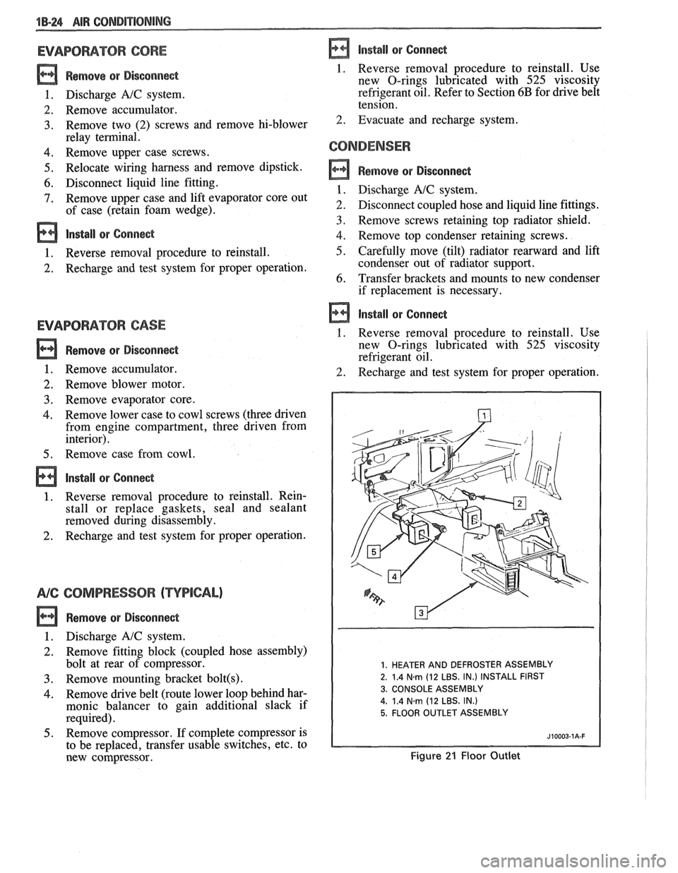
1. HEATER AND DEFROSTER ASSEMBLY
2. 1.4
N.m (12 LBS. IN.) INSTALL FIRST
3. CONSOLE ASSEMBLY
4.
1.4 Narn (12 LBS. IN.)
5. FLOOR OUTLET ASSEMBLY
Figure 21 Floor Outlet
Page 68 of 1825
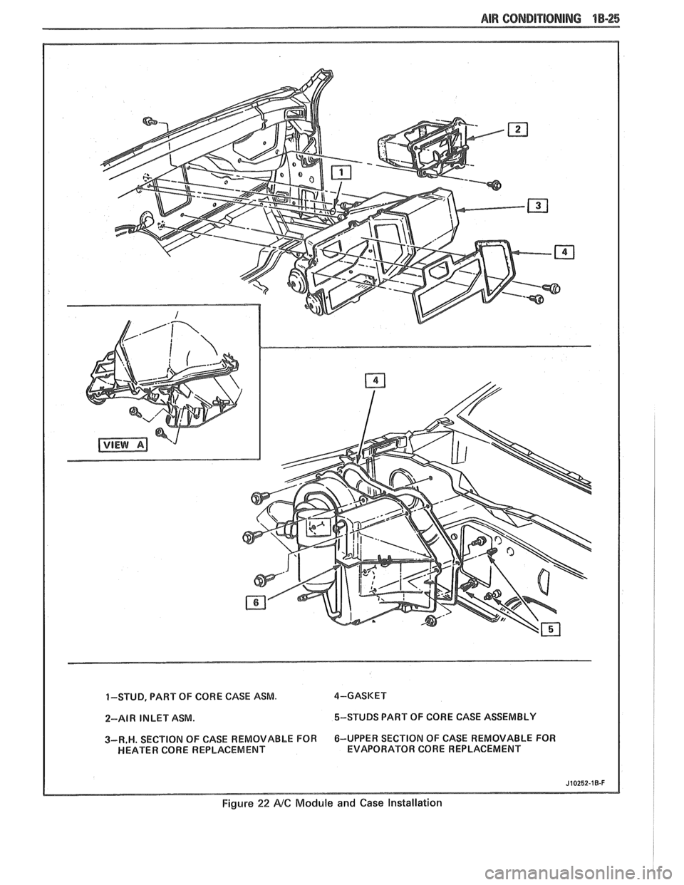
1-STUD, PART OF CORE CASE ASM. 4-GASKET
2-A1 W IN LET ASM. 5-STUDS
PART OF CORE CASE ASSEMBLY I 3-R.W. SECT ION OF CASE REMOVABLE FOR 6-UPPER
SECTION OF CASE REMOVABLE FOR
HEATER CORE REPLACEMENT EVAPORATOR CORE REPLACEMENT
Figure 22 NC Module
and Case lnstallarion
Page 69 of 1825
1B-26 AIR CONDITIONING
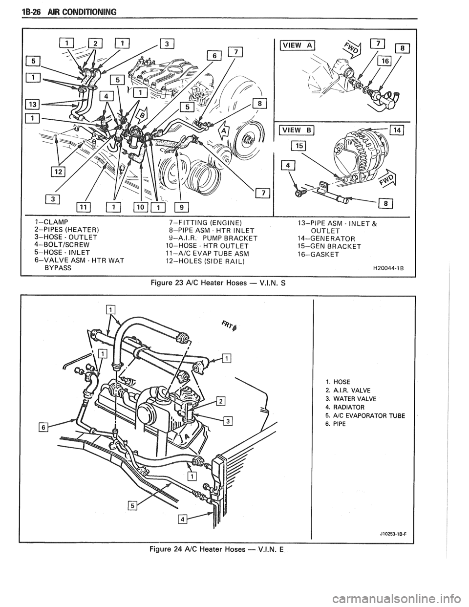
7-FITTING (ENGINE)
13-PIPE ASM - INLET & 8-PIPE ASM - HTR INLET
OUTLET
9-A.I.R. PUMP BRACKET 14-GENERATOR
10-HOSE
- HTR OUTLET
15-GEN BRACKET 11-AIC EVAP TUBE ASM 16-GASKET
12-HOLES (SIDE RAIL)
Figure 23 NC Heater Hoses - V.I.N. S
2. A.I.R. VALVE
3. WATER VALVE
4. RADIATOR
5. AIC EVAPORATOR TUBE
Figure 24 NC Heater Hoses - V.I.N. E
Page 70 of 1825
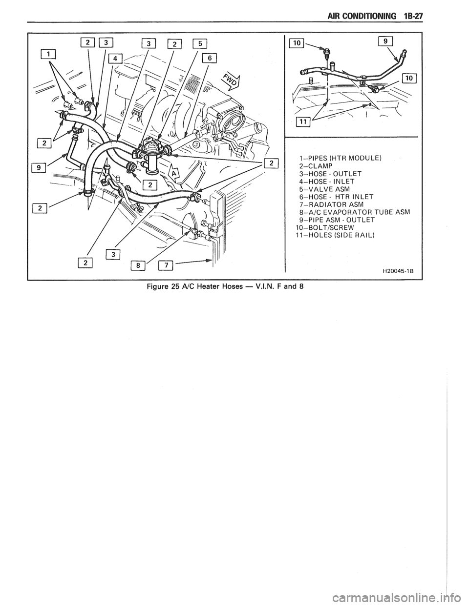
1-PIPES (HTR MODULE)
2-CLAMP
3-HOSE
- OUTLET
4-HOSE
- INLET
5-VALVE ASM
6-HOSE
- HTR INLET
7-RADIATOR ASM
8-A/C EVAPORATOR TUBE ASM
9-PIPE ASM
- OUTLET
10-BOLTISCREW
11-HOLES (SIDE RAIL)
Figure 25 A/C Heater Hoses - V.I.N. F and 8
Page 360 of 1825
2.8 LITER V-6 6A2-9
INTAKE MANIFOLD (FIGURE 6A2-7)
Removal
Disconnect battery.
Remove air cleaner.
Drain coolant.
Refer to Section 6E3 for removal of the following
PFI sub-assemblies.
e Plenum
e Fuel Rail
e Runner
Disconnect spark plug wires at spark plugs.
Disconnect wires at coil.
Remove distributor cap and spark plug wires.
Mark distributor position and remove hold down
bracket.
Remove distributor.
Remove air management hose, manual
transmission only.
Disconnect emission canister hoses. Remove pipe
bracket (front left valve cover).
Remove left valve cover.
Remove air management bracket, manual
transmission only.
Remove right valve cover.
Remove upper radiator hose.
Disconnect heater hose.
Disconnect coolant switches.
Remove manifold bolts.
Remove manifold. Discard manifold gaskets and
remove loose RTV from front and rear ridges of
cylinder case.
Installation
When installing intake gaskets, notice that the
gaskets are marked Right Side and Left Side
(carbureted only). Use them only as indicated to
maintain designed efficiency of this engine.
1. Make
sure that no oil or water is present on
surface when new RTV is applied. Place a 5mm
diameter
(3/16") bead of RTV, # 1052917 or
equivalent, on each ridge.
2. Install
new intake gaskets on cylinder heads.
Hold in place by extending ridge RTV bead up
6mm onto the gasket ends. The new intake
gaskets will have to be cut, where indicated, to
install behind push rods. Cut only those areas
that are necessary.
3. Install intake
manifold on engine. Make sure
areas between case ridges and intake are
completely sealed.
4. Install manifold retaining bolts and nuts and
torque in the sequence shown in Figure 6A2-7.
5. Install heater and radiator hose to manifold.
6. Install rocker covers as previously outlined.
7. Connect coolant switches.
8. Install air management bracket.
9. Install pipe bracket (front left rocker cover).
10. Install distributor, distributor cap and retaining
nut. Do not tighten.
11. Refer to Section 6E3 for installation of PFI
sub-assemblies removed. 12.
Connect
necessary wires and hoses.
13. Fill cooling system with
the proper mixture of
ethylene glycol anti-freeze and water. Do not
install radiator cap.
14. Start
engine, set intitial timing. After set, torque
distibutor hold down clamp bolt to 34
N-m (25
lb. ft.). Recheck timing after torquing bolt.
15. Let engine
run until radiator upper hose becomes
hot (thermostat open).
16. With
engine idling, add coolant to radiator, if
necessary, until level reaches bottom of filler
neck.
17. Install
radiator cap, making sure arrows on cap
line up with overflow tube.
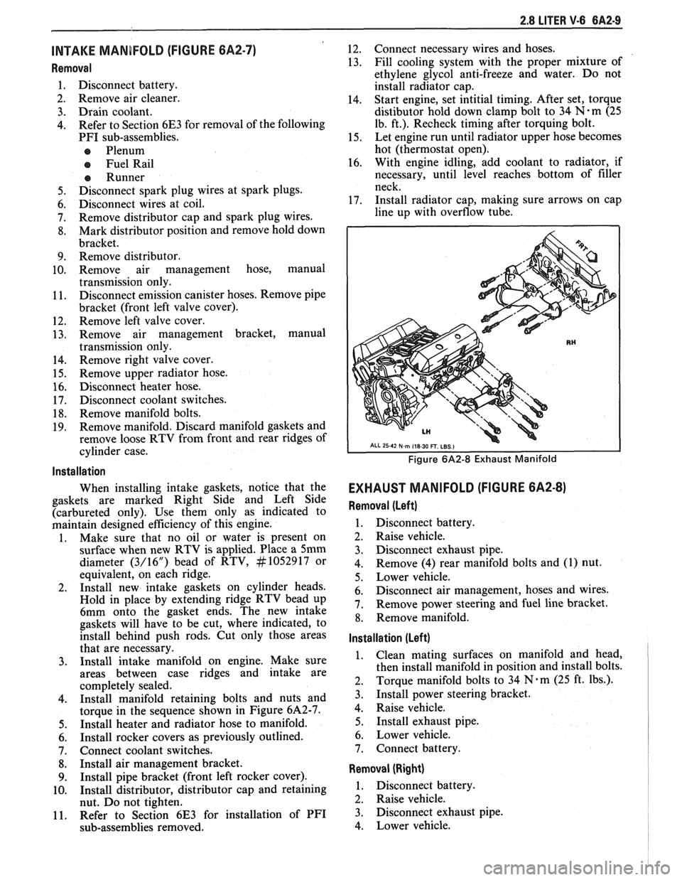
Figure 6A2-8 Exhaust Manifold
EXHAUST MANIFOLD (FIGURE 6A2-8)
Removal (Left)
1. Disconnect battery.
2. Raise vehicle.
3. Disconnect exhaust pipe.
4. Remove
(4) rear manifold bolts and (1) nut.
5. Lower vehicle.
6. Disconnect air management, hoses and wires.
7. Remove power steering and fuel line bracket.
8. Remove manifold.
Installation (Left)
1. Clean mating surfaces on manifold and head,
then install manifold in position and install bolts.
2. Torque
manifold bolts to 34
N.m (25 ft. lbs.).
3. Install power steering bracket.
4. Raise vehicle.
5. Install exhaust pipe.
6. Lower vehicle.
7. Connect battery.
Removal (Right)
1. Disconnect battery.
2. Raise vehicle.
3. Disconnect exhaust pipe.
4. Lower vehicle.
Page 366 of 1825
2.8 LITER V.6 6A2-15
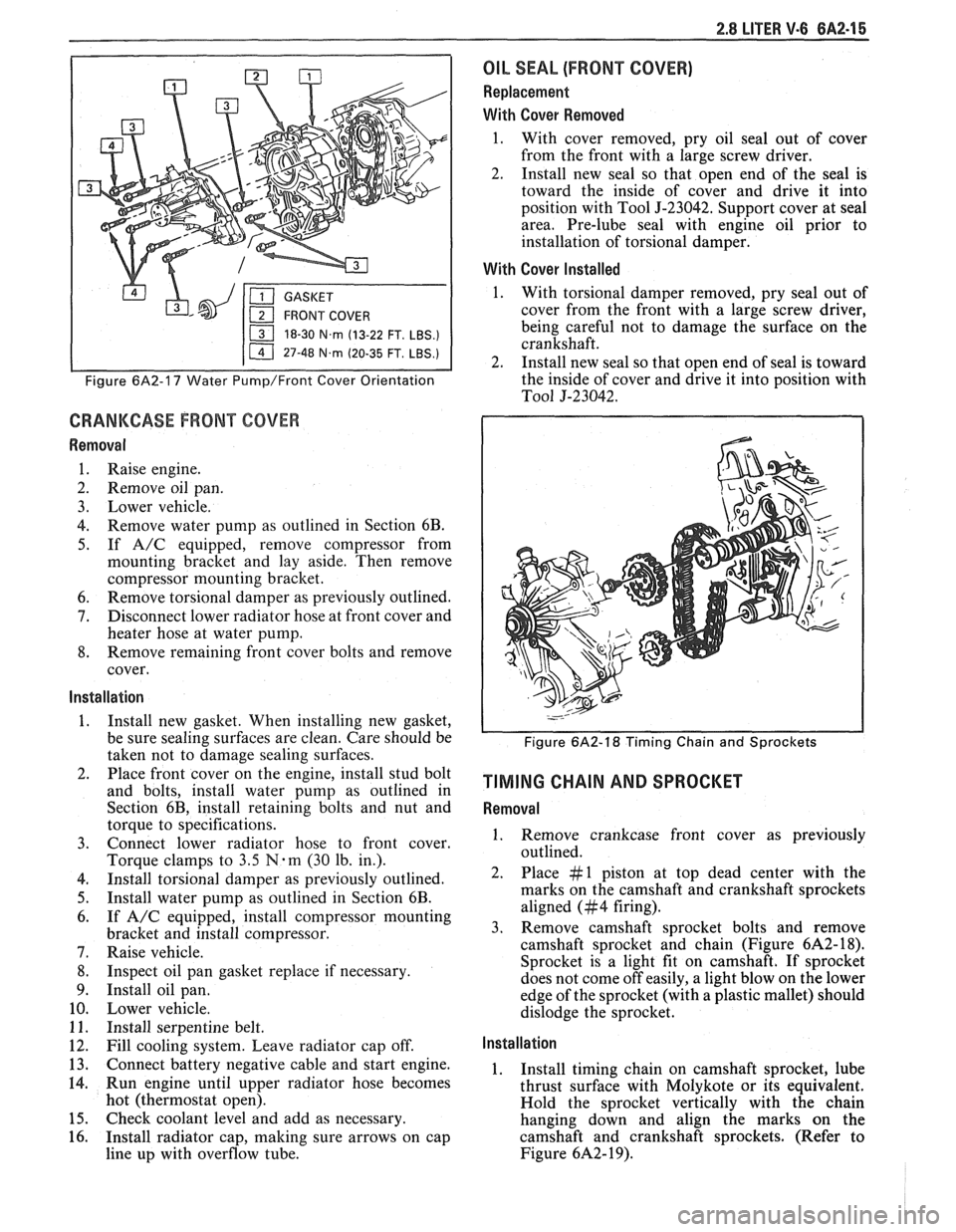
18-30 N.m (13-22 FT. LBS.)
I 11 47-48 N.m (20-35 FT. LBS.) I
Figure 6A2-17 Water Pump/Front Cover Orientation
CRANKCASE FRONT COVER
Removal
1. Raise engine.
2. Remove oil pan.
3. Lower vehicle.
4. Remove water pump as outlined in Section 6B.
5. If A/C equipped, remove compressor from
mounting bracket and lay aside. Then remove
compressor mounting bracket.
6. Remove torsional damper as previously outlined.
7. Disconnect lower radiator hose at front cover and
heater hose at water pump.
8. Remove remaining front cover bolts and remove
cover.
Installation
1. Install new gasket. When installing new gasket,
be sure sealing surfaces are clean. Care should be
taken not to damage sealing surfaces.
2. Place front cover on the engine, install stud bolt
and bolts, install water pump as outlined in
Section 6B, install retaining bolts and nut and
torque to specifications.
3. Connect lower radiator hose to front cover.
Torque clamps to
3.5 N-m (30 lb. in.).
4. Install torsional damper as previously outlined.
5. Install water pump as outlined in Section 6B.
6. If A/C equipped, install compressor mounting
bracket and install compressor.
7. Raise vehicle.
8. Inspect oil pan gasket replace if necessary.
9. Install oil pan.
10. Lower vehicle.
11. Install serpentine belt.
12. Fill cooling system. Leave radiator cap off.
13. Connect battery negative cable and start engine.
14. Run engine until upper radiator hose becomes
hot (thermostat open).
15. Check coolant level and add as necessary.
16. Install radiator cap, making sure arrows on cap
line up with overflow tube.
OIL SEAL (FRONT COVER)
Replacement
With Cover Removed
1. With cover removed, pry oil seal out of cover
from the front with a large screw driver.
2. Install new seal so that open end of the seal is
toward the inside of cover and drive it into
position with Tool
5-23042. Support cover at seal
area. Pre-lube seal with engine oil prior to
installation of torsional damper.
With Cover Installed
1. With torsional damper removed, pry seal out of
cover from the front with a large screw driver,
being careful not to damage the surface on the
crankshaft.
2. Install new seal so that open end of seal is toward
the inside of cover and drive it into position with
To01 5-23042.
Figure 6A2-18 Timing Chain and Sprockets
TIMING CHAIN AND SPROCKET
Removal
1. Remove crankcase front cover as previously
outlined.
2. Place #1 piston at top dead center with the
marks on the camshaft and crankshaft sprockets
aligned (#4 firing).
3. Remove camshaft sprocket bolts and remove
camshaft sprocket and chain (Figure
6A2- 18).
Sprocket is a light fit on camshaft.
If sprocket
does not come off easily, a light blow on the lower
edge of the sprocket (with a plastic mallet) should
dislodge the sprocket.
Installation
1. Install timing chain on camshaft sprocket, lube
thrust surface with Molykote or its equivalent.
Hold the sprocket vertically with the chain
hanging down and align the marks on the
camshaft and crankshaft sprockets. (Refer to
Figure
6A2- 19).
Page 376 of 1825
2.8 LITER V-6 6A2-25
Fitting
1. Select rings comparable in size to the piston being
used.
2. Slip
the compression ring in the cylinder bore;
then press the ring down into the cylinder bore
about 6mm above ring travel. Be sure ring is
square with cylinder wall.
3. Measure the space or gap between the ends of the
ring with a feeler gage (Figure
6A2-33).
4. If
the gap between the ends of the ring is below
specifications, remove the ring and try another
for fit.
5. Fit each compression ring to the cylinder in
which it is going to be used.
6. If the pistons have not been cleaned and inspected
as previously outlined, do so.
7. Slip the outer surface of the top and second
compression ring into the respective piston ring
groove and roll the ring entirely around the
groove (Figure
6A2-34). If binding occurs at any
point, the cause should be determined. If there is
a ring groove, remove by dressing with a fine cut
file. If the binding is caused by a distorted ring,
check a new ring.
Installation
1. Install oil ring spacer in groove being sure ends
are butted and not overlapped.
2. Hold
spacer ends butted and install lower steel oil
ring rail.
3. Install upper
steel oil ring rail with gap staggered.
4. Flex
the oil ring assembly to make sure ring is
free. If binding occurs, the cause should be
detemined. If caused by ring groove, remove by
dressing groove with a fine cut file. If binding is
caused by a distorted ring, check a new ring.
5. Install second compression ring. Stagger gap
from other rings.
6. Install top compression ring with gap properly
located.
ENGINE ASSEMBLY
Removal
Disconnect battery.
Remove air cleaner.
Remove hood. Drain radiator.
Remove lower radiator hose.
Remove upper fan shroud.
Remove upper radiator hose and coolant
recovery hose.
Remove transmission cooler lines. Remove radiator.
Remove fan assembly.
Remove heater hoses.
Disconnect carburetor linkage, includes cruise
control detent cable.
Remove vacuum brake booster line.
Remove distributor cap and lay wiring aside.
Disconnect necessary wires and hoses.
Remove power steering pump and lay aside. Raise
vehicle.
Remove exhaust pipes at exhaust manifold.
Remove dust cover.
Remove converter bolts.
Disconnect starter wires.
Remove bell housing bolts.
Remove motor mount through bolts.
Disconnect fuel lines at fuel pump.
Lower vehicle. Support transmission.
Remove
A.I.R./Converter pipes bracket.
Remove engine, include removing wire from
bracket at rear left of engine.
Installation
Position engine assembly in vehicle.
Attach motor mount to engine brackets and
lower engine in place.
Remove engine lifting device.
Remove transmission floor jack.
Raise vehicle on hoist.
Install mount "through" bolts. Torque to
specifications.
Install bell housing bolts. Torque to
specifications.
On vehicles with automatic transmission, install
converter to flywheel attaching bolts. Torque to
specifications.
Install flywheel splash shield of conveter housing
cover as applicable. Torque attaching bolts to
specifications.
Install starter wires.
Connect fuel lines.
Connect exhaust pipe at manifold.
Lower vehicle on hoist.
Reinstall power steering pump, if so equipped.
Connect necessary wires and hoses.
Install radiator and fan shroud and reconnect
radiator and heater hoses.
Fill cooling system.
Fill crankcase with oil. See owner's manual for
specifications.
Install air cleaner.
Install hood.
Connect battery cables.
NOTICE: To avoid possible arcing of battery,
connect positive battery cable first.
22. Start engine, check for leaks and check timing.
CRANKSHAFT
The crankshaft can be removed while the engine
is dissasembled for overhaul, as previously outlined or
without complete disassembly.
Removal
1. With the engine removed from the vehicle,
remove the clutch assembly (if equipped) and
flywheel. Mount engine in stand and clamp
securely.