1988 PONTIAC FIERO heater
[x] Cancel search: heaterPage 1338 of 1825
HEATER
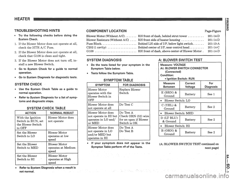
TROUBLESMOOTlNG HINTS
e Try the following checlcs before doing the
System Check.
1. If the Blower Motor does not operate at all,
check the
HTR A/C Fuse.
2. If the Blower Motor does not operate at all,
check that
GI08 is clean and tight.
3. If the Blower Motor does not turn off, in-
stall
a new Blower Switch.
r Go to System Check for a guide to normal
operation.
r Go to System Diagnosis for diagnostic tests.
SYSTEM CHECK
Use the System Check Table as a guide to
normal operation.
e Refer to System Diagnosis for a list of symp-
toms and diagnostic steps.
SYSTEM CHECK TABLE
ACTION 1 NORMALRESUU 1
COMPONENT LOCATION Page-Figure
Blower Motor (Without
AlC) ....... RH front of dash, behind strut tower .......... 201-14-D
Blower Resistors (Without AIC) .... RH front side of heater housing .............. 201-14-D
Fuse Block.
..................... Behind LH side of IIP, below light switch. ...... 201-10-8
C202 (1 cavity) .................. Behind center of UP, near control head. ........ 201-14-C
GPO8 .......................... RH front of dash, above center of Blower Motor . 201-14-D
SYSTEM DIAGNOSIS
Do the tests listed for your symptom in the
Symptom Table below.
Tests follow the Symptom Table.
SYMPTOM TABLE
A: BLOWER SWITCH TEST
0 If your symptom does not appear in the (A: BLOmR SWITCH TEST continued on Sympton Table perForm all of the Tests. next page)
not normal. Measure:
VOLTAGE
At: BLOWER
SWITCH CONNECTOR
(Connected)
Condition:
a ignition Switch: RUN
Measure Correct For
Between Voltage Diagnosis
P P
See 1
Blower Switch: LO
&
Ground Battery
See 2
* Blower
Switch: MED
(LT BLU)
& Ground
* Blower Switch: HI
Battery
See 2
Page 1339 of 1825
HEATER
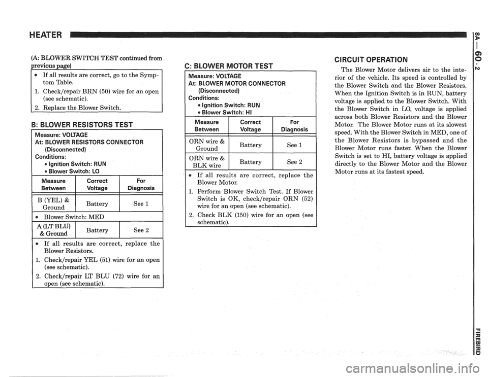
(A: BLOWER SWITCH TEST continued from
previous page)
1. Check/repair BRN (50) wire for an open
(see schematic).
3: BLOWER RESlSTORS TEST
Measure: VOLTAGE
At: BLOWER RESISTORS CONNECTOR
(Disconnected)
Conditions:
* lgnition Switch: RUN
Blower Switch: LO
Measure Correct
For
Between Voltage
Diagnosis
[ 0 Blower Switch: MED
A(LTBLU' I Battery I See 2 & Ground I
2 BLOWER MOTOR TEST
R CONNECTOR
(Disconnected)
Conditions:
* lgnition Switch: RUN
ORN wire & Battery Ground See 1
ORN wire & I Battery I See 2 BLK wire I
0 If
all results are correct, replace the
Blower Motor.
1. Perform Blower Switch Test. If Blower
Switch is OK,
check/repair ORN (52)
wire for an open (see schematic).
2. Check BLK (150) wire for an open (see
schematic).
CIRCUIT OPERATION
The Blower Motor delivers air to the inte-
rior of the vehicle. Its speed is controlled by
the Blower Switch and the Blower Resistors.
When the Ignition Switch is in RUN, battery
voltage is applied to the Blower Switch. With
the Blower Switch in LO, voltage is applied
across both Blower Resistors and the Blower
Motor. The Blower Motor runs at its slowest
speed. With the Blower Switch in MED, one of
the Blower Resistors is bypassed and the
Blower Motor runs faster. When the Blower
Switch is set to
HI, battery voltage is applied
directly to the Blower Motor and the Blower
Motor runs at its fastest speed.
0 If all results are correct, replace the
Blower Resistors.
1. Check/repair YEL (51) wire for an open
(see schematic).
2. Check/repair LT BLU (72) wire for an
open (see schematic).
Page 1366 of 1825
AIR CONDITIONING: AlR DELIVERY
660, MANUAL
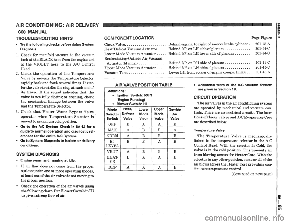
TROUBLESHOOTING HINTS
Try the following checks before doing System
Diagnosis.
1. Cheek for manifold vacuum to the vacuum
tank at the BLACK hose from the engine and
at the VIOLET hose to the
A/C Control
Head.
2. Check the operation of the Temperature
Valve by moving the Temperature Selector
rapidly back and forth several times. Listen
for the valve to strike the stop at each end of
its travel.
If the sound indicates that the
valve is not fully closing or opening, check
the mechanical linkage between the valve
and the Temperature Selector.
3. Check that Heater Water Bypass Valve
operates when Temperature Selector is
moved to maximum cold position.
Go to the AlC System Check in 8A-62 for a
guide to normal operation and diagnostic ref-
erences for the entire
AIC System.
r Go to Systern Diagnosis to isolate air delivery
conditions.
SYSTEM DIAGNOSIS
Engine vvarm and running at idle.
If air flow does not come from the proper
outlets under one or more operating modes,
at least one of the air valves is not moving to
the proper position.
Check the operation of the air valves using
the following chart. Put Blower Switch in
HI
to give a strong flow of air.
COMPONENT LOGATlORl Page-Figure
Check Valve.
. . . . . . . . . . . . . . . . . . . . Behind engine, to right of master brake cylinder . 201-15-A
HeatIDefrost Vacuum Actuator . . . . Behind IIP, on LN side of plenum . . . . . . . . . . . . . 201-14-6
Lower Mode Vacuum Actuator
. . . . . Behind I/P, on LH lower side of plenum . . . . . . . . 201-14-C
Recirculating-Outside Air Vacuurn
Actuator (Manual) . . . . . . . . . . . . . . Behind IIP, on RH side of plenum. . . . . . . . . . . . . 201-14-6
Upper Mode Vacuum Actuator
. . . . . Behind I/P, on LN side of plenum . . . . . . . . . . . . . 201-14-6
Vacuum Tank
. . . . . . . . . . . . . . . . . . . Lower LIH front corner of engine compartment . . 201-15-A
AIR VALVE POSlTlON TABLE * Additional tests of the Ale Vacuum System
are given in Section
1 B.
GIWCUiT OPEMTIOIU
The air valves in the air conditioning system
are operated by mechanical and vacuum con-
trols. There are no electrical circuits. The func-
tions of the air valves and
A/C Evaporator Core
are described below.
Temperature Valve
The Temperature Valve is mechanically
linked to the temperature selector in the
AIC
Control Head. With the selector in Cold, the
valve is in the cold position. This prevents air
from blowing across the Heater Core. With the
selector in any other position, some or
all of the
air blows across the Heater Core providing con-
tinuous temperature control.
(Continued on next page)
Page 1367 of 1825
AIR CORIDI"F0NING: AIR DELIVERY
C60, MANUAL
(Continued from previous page)
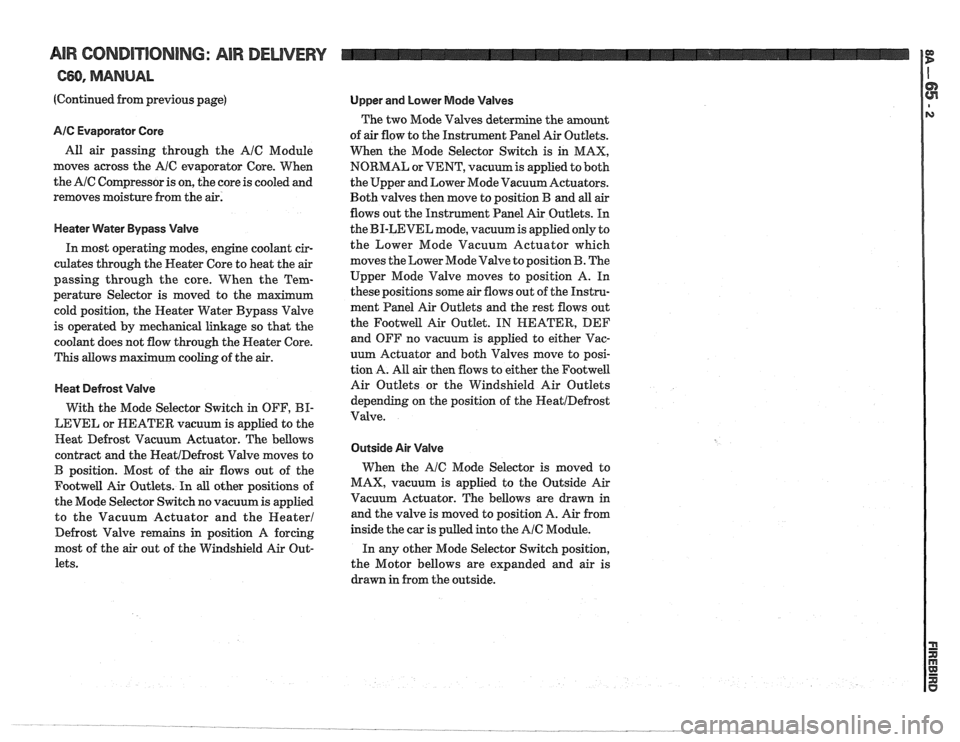
AIC Evaporator Core
All air passing through the AIC Module
moves across the
A/C evaporator Core. When
the
AIC Compressor is on, the core is cooled and
removes moisture from the air.
Heater Water Bypass Valve
In most operating modes, engine coolant cir-
culates through the Heater Core to heat the
air
passing through the core. When the Tem-
perature Selector is moved to the maximum
cold position, the Heater Water Bypass Valve
is operated by mechanical linkage so that the
coolant does not flow through the Neater Core.
This allows maximum cooling of the
air.
Heat Defrost Valve
With the Mode Selector Switch in OFF, BI-
LEVEL or NEATER vacuum is applied to the
Heat Defrost Vacuum Actuator. The bellows
contract and the
HeatIDefrost Valve moves to
B position. Most of the air flows out of the
Footwell Air Outlets. In all other positions of
the Mode Selector Switch no vacuum is applied
to the Vacuum Actuator and the
Heater1
Defrost Valve remains in position A forcing
most of the
air out of the Windshield Air Out-
lets.
Upper and Lower Mode Valves
The two Mode Valves determine the amount
of
air flow to the Instrument Panel Air Outlets.
When the Mode Selector Switch is in MAX,
NORMAL or VENT, vacuum is applied to both
the Upper and Lower Mode Vacuum Actuators.
Both valves then move to position B and
all air
flows out the Instrument Panel Air Outlets. In
the BI-LEVEL mode, vacuum is applied only to
the Lower Mode Vacuum Actuator which
moves the Lower Mode Valve to position
B. The
Upper Mode Valve moves to position A. In
these positions some air flows out of the Instru-
ment Panel Air Outlets and the rest flows out
the
Footwell Air Outlet. IN HEATER, DEF
and OFF no vacuum is applied to either Vac-
uum Actuator and both
Valves move to posi-
tion A. All
air then flows to either the Footwell
Air Outlets or the Windshield Air Outlets
depending on the position of the
HeatIDefrost
Valve.
Outside Air Valve
When the AIC Mode Selector is moved to
MAX, vacuum is applied to the Outside Air
Vacuum Actuator. The bellows are drawn in
and the valve is moved to position A. Air from
inside the car is pulled into the
AIC Module.
In any other Mode Selector Switch position,
the Motor bellows are expanded and air is
drawn in from the outside.
Page 1389 of 1825
AIR CONDITIONING: AIR DELIVERY I g
667, ELECTRONIC
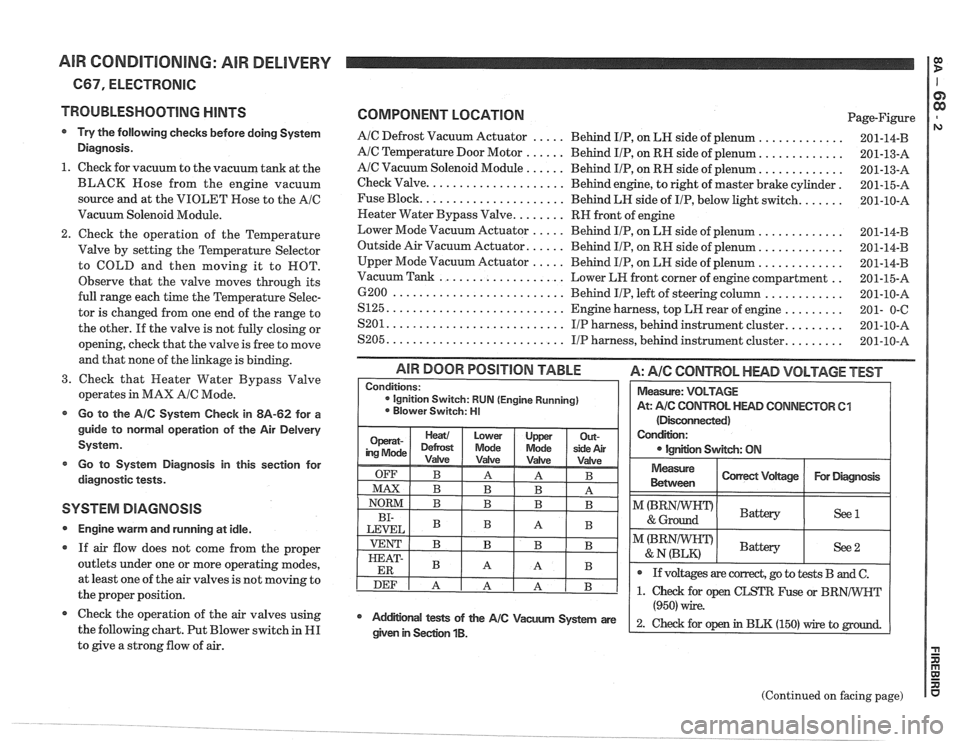
TROUBLESHOOTING
HINTS
Try the following checks before doing System
Diagnosis.
1. Check for vacuum to the vacuum tank at the
BLACK Hose from the engine vacuum
source and at the VIOLET Rose to the
AIC
Vacuum Solenoid Module.
Check the operation of the Temperature
Valve by setting the Temperature Selector
to COLD and then moving it to ROT.
Observe that the valve moves through its
full range each time the Temperature Selec-
tor is changed from one end of the range to
the other. If the valve is not fully closing or
opening, check that the valve is free to move
and that none of the linkage is binding.
3. Check that Heater Water Bypass Valve
operates in MAX
AIC Mode.
Go to the AIC System Check in 8A-62 for a
guide to normal operation of the Air
Delvery
System.
Go to System Diagnosis
in this section for
diagnostic tests.
SYSTEM DIAGNOSIS
Engine warm and running at idle.
If air flow does not come from the proper
outlets under one or more operating modes,
at least one of the air valves is not moving to
the proper position.
@ Check the operation of the air valves using
the following chart. Put Blower switch in
HI
to give a strong flow of air.
COMPONENT LOCATION Page-Figure
AIC Defrost Vacuum Actuator ..... Behind IIP, on LH side of plenum .............
AIC Temperature Door Motor ...... Behind IIP, on RH side of plenum. ............
AIC Vacuum Solenoid Module ...... Behind IIP, on RH side of plenum. ............
Check Valve. .................... Behind engine, to right of master brake cylinder.
Fuse Block.
..................... Behind LH side of IIP, below light switch. ......
Neater Water Bypass Valve. ....... RH front of engine
Lower Mode Vacuum Actuator
..... Behind IIP, on LH side of plenum .............
Outside Air Vacuum Actuator. ..... Behind IIP, on RH side of plenum. ............
Upper Mode Vacuum Actuator ..... Behind IIP, on LH side of plenum .............
.. Vacuum Tank ................... Lower LH front corner of engine compartment
6200
.......................... Behind IIP, left of steering column ............
S125. .......................... Engine harness, top LH rear of engine .........
........ S201. .......................... IIP harness, behind instrument cluster.
........ S205. .......................... IIP harness, behind instrument cluster.
(Disconnected)
Condition:
IgnEon Swgch: ON
AIR DOOR POSITION TABLE A: AIC CONTROL HEAD VOLTAGE TEST
Measure
Between I Correct Vdtage / For Diagmsk I
Conditions: ignition Switch: RUN (Engine Running)
Blower Switch: HI
I"(BRNIWIFDI & Ground Battery ( See1 I
Measure: VOLTAGE
At:
A/C CONTROL HEAD CONNECTOR 61
I I
@ If voltages are correct, go to tests B and C.
(Continued on facing page)
Mdifional tests of the AIC Vacum System are
(950) wire.
2- ~hd for op in BLK (150) rrire to given in Seclion 1B.
Page 1391 of 1825
AIR CONDITIONING: AIR DELIVERY
(Continued from previous page)
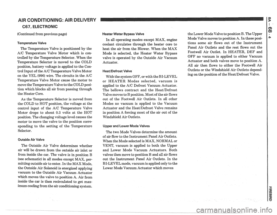
Temperature Valve
The Temperature Valve is positioned by the
A/C Temperature Valve Motor which is con-
trolled by the Temperature Selector. When the
Temperature Selector is moved to the COLD
position, battery voltage is applied to the Con-
trol Input of the
AIC Temperature Valve Motor
on the YEL
(996) wire. The circuits in the Ale
Temperature Valve Motor cause the motor to
move the Temperature Valve to the COLD posi-
tion which blocks all air from passing through
the Heater Core.
As the Temperature Selector is moved from
the COLD to ROT position, the voltage at the
control input of the
AIC Temperature Valve
Motor drops to about
0.3 volts at the HOT
position. The changing voltage level causes the
motor to move the valve to the position corre-
sponding to the setting of the Temperature
Selector.
Outside Air Valve
The Outside Air Valve determines whether
air will be drawn from the outside air inlet or
from inside the car. The valve is in position
B
(see schematic) in all modes except MAX, per-
mitting outside air to enter. In the MAX Mode,
the Outside Air Solenoid is energized applying
vacuum to the Outside Air Vacuum Actuator
which moves the valve to position A. Air from
inside the car is then recirculated to get max-
imum cooling from the
air conditioning system.
Heater Water Bypass Valve
In all operating modes except MAX, engine
coolant circulates through the heater core to
heat the
air from the Blower. When the MAX
Mode is selected, the
Neater Water Bypass
valve is operated by the Outside Air Vacuum
Actuator.
HeatIDefrost Valve
With the system OFF, or with the BI-LEVEL
or HEATER Modes selected, vacuum is
applied to the
AIC Defrost Vacuum Actuator.
The bellows contract and the
HeatIDefrost
Valve moves to B position. Most of the air flows
out of the
Footwell Air Outlets. In all other
Modes no vacuum is applied to the Vacuum
Actuator and the
HeatIDefrost Valve remains
in position A forcing most of the air out of the
Windshield Air Outlets.
Upper and Lower Mode Valves
The two Mode Valves determine the amount
of
air flow to the Instrument Panel Air Outlets.
When the Mode selected is MAX, NORMAL or
VENT, vacuum is applied to both the Upper
and Lower Mode Vacuum Actuators. Both
valves then move to position
B and all air flows
out the Instrument Panel Air Outlets. In the
BI-LEVEL mode,
vacuumis applied only to the
Lower Mode Vacuum Actuator which moves the
Lower Mode Valve to position
B. The Upper
Mode Valve moves to position
A. In these posi-
tions some air flows out of the Instrument
Panel Air Outlets and the rest flows out the
Footwell Air Outlet. In HEATER, DEF and
OFF no vacuum is applied to either Vacuum
Actuator and both valves move to position A.
AU. air then flows to either the Footwell Air
Outlets or the Windshield Air Outlets depend-
ing on the position of the
NeatIDefrost Valve.
Page 1499 of 1825
INTERIOR LIGHTS DIMMING
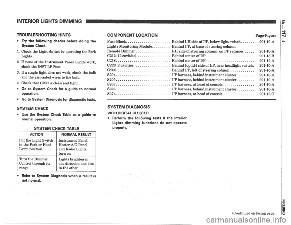
TROUBLESHOOTlNG HINTS COMPONENT LOGATlON Page-Figure
a Try the following checks before doing the Fuse Block. ..................... Behind LN side of IIP, below light switch. ...... 201-10-A
System Check. Lights Monitoring Module. ........ Behind IIP, at base of steering column
................. ..... 1. Check the Light Switch by operating the Park RN
side of steering column, on IIP retainer 201-10-A
................ ........................ Lights. 6212 (12-cavities) Behind center of IIP 201-13-B -
.......................... ........................ 2. If none of the Instrument Panel Lights work, C218. Behind center of IIP 201-12-A
................. check the INST LP Fuse. C220 (2 cavities) Behind top LH side of IIP, near headlight switch. 201-10-A
............ 6200 .......................... Behind IIP, left of steering column 201-10-A
3. If a single light does not work, cheek the bulb ........ S204. .......................... IIP harness, behind instrument cluster. 201-10-A and the associated wires to the bulb. ........ S205. .......................... IIP harness, behind instrument cluster. 201-10-A
4. Check that 6200 is clean and tight. ............... S207. .......................... IIP harness, at head of console. 201-10-A
@ Go to System Check for a guide to normal S225. .......................... IIP harness, behind instrument cluster. ........ 201-10-A
operation. $274. .......................... IIP harness, at head of console. ............... 201-12-C
s Go to System Diagnosis for diagnostic tests.
SYSTEM CHECK SYSTEM DIAGNOSIS
Use the System Check Table as a guide to WITH DIGITAL CLUSTER
normal operation. r Perform
the follbking tests if the Interior
Lights dimming functions do not operate
properly.
SYSTEM CHECK TABLE
ACTION
Put the Light Switch
in the Park or
Head
Lamp position
Refer to System Diagnosis when a result is
not normal.
NORMAL RESULT
Instrument Panel,
Heater-AIC Panel,
and Radio Lights
turn on
Turn the Dimmer
Control through its
range
(Continued on facing page)
Lights brighten
in
one direction and dim
in the other
Page 1553 of 1825
RADIO I
(Continued from previous page) from back of Radio
If noise persists with replacement antenna, the
problem must be repaired at the source of noise
(generator, ignition system, accessory, etc.). See
Delco Manual for noise "Sniffing" procedures.
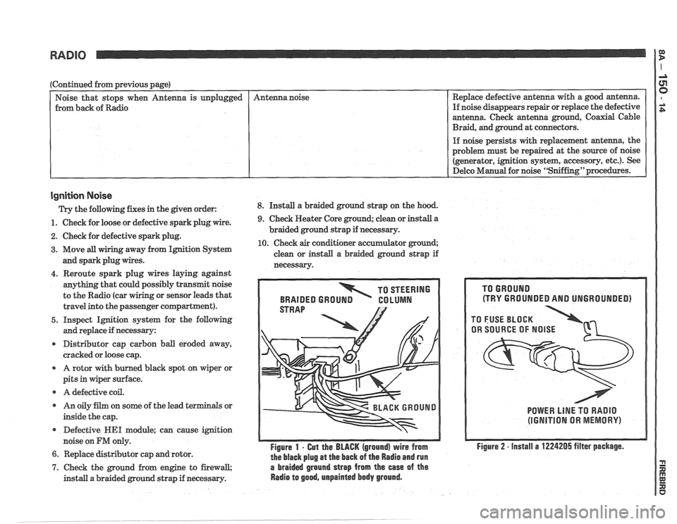
Ignition Noise
Trv the following. fixes in the piven order: 8. Install a braided ground strap on the hood. Replace
defective antenna with a good antenna.
If noise disappears repair or replace the defective
antenna. Check antenna ground, Coaxial Cable
Braid, and ground at connectors.
unplugged
- -
1. Check
for loose or defective spark plug wire.
2. Check for defective spark plug.
3. Move all wiring away from Ignition System
and spark plug wires. Antenna
noise
4. Reroute spark plug wires laying against
anything that could possibly transmit noise
to the Radio (car
g or sensor leads that
travel into the passenger compartment).
5. Inspect Ignition system for the following
and replace if necessary:
r Distributor cap carbon ball eroded away,
cracked or loose cap.
A rotor with burned black spot on wiper or
pits in wiper surface.
r A defective coil.
r An oily film on some of the lead terminals or
inside the cap.
Defective
WE1 module; can cause ignition
noise on
FM only.
6. Replace distributor cap and rotor.
9. Check Heater Core ground; clean or install a
braided ground strap if necessary.
10. Check air conditioner accumulator ground;
clean or install a braided ground strap if
necessarv.
TO STEERING
BRAIDED
GROUN GO LUMN
Figure 1 - Gut the BLACK (ground) wire from
the black plug
at the back of the Radio and run
7. Check the ground from engine to firewall, a braided ground strap from the ease of the
install a braided ground strap if necessary. Radio to good, unpainted body ground.
(TRY GROUNDED AND UNGROUNDED)
POWER LlNE TO RADIO
(IGNITION OR MEMORY)
Figure 2 - install a 1224205 filter package.