1988 PONTIAC FIERO distributor order
[x] Cancel search: distributor orderPage 367 of 1825
6A2-16 2.8 LITER V-6
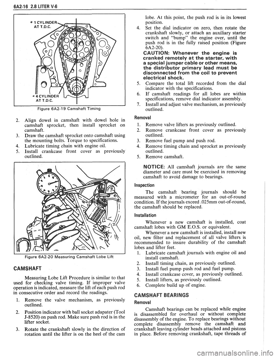
Figure 6A2-19 Camshaft Timing
2. Align dowel in camshaft with dowel hole in
camshaft sprocket, then install sprocket on
camshaft.
3. Draw the camshaft sprocket onto camshaft using
the mounting bolts. Torque to specifications.
4. Lubricate timing chain with engine oil.
5. Install crankcase front cover as previously
outlined.
Figure 6A2-20 Measuring Camshaft Lobe Lift
CAMSHAFT
Measuring Lobe Lift Procedure is similar to that
used for checking valve timing. If improper valve
operation is indicated, measure the lift of each push rod
in consecutive order and record the readings.
1. Remove the valve mechanism, as previously
outlined.
2. Position
indicator with ball socket adapater (Tool
5-8520) on push rod. Make sure push rod is in the
lifter socket.
3. Rotate the crankshaft slowly in the direction of
rotation until the lifter is on the heel of the cam lobe.
At this point, the push rod is in its lowest
position.
4. Set the dial indicator on zero, then rotate the
crankshaft slowly, or attach an auxiliary starter
switch and "bump" the engine over, until the
push rod is in the fully raised position (Figure
6A2-20).
CAUTION: Whenever the engine is
cranked remotely at the starter, with
a special jumper cable or other means,
the distributor primary lead must be
disconnected from the coil to prevent
electrical shock.
5. Compare the total lift recorded from the dial
indicator with the specifications.
6. If camshaft readings for all lobes are within
specifications, remove dial indicator assembly.
7. Install and adjust valve mechanism, as previously
outlined.
Removal
1. Remove valve lifters as previously outlined.
2. Remove crankcase front cover as previously
outlined.
3. Remove fuel pump and push rod.
4. Remove timing chain and sprocket as previously
outlined.
5. Remove camshaft.
NOTICE: All camshaft journals are the same
diameter and care must be exercised in removing
camshaft to avoid damage to bearings.
Inspection
The camshaft bearing journals should be
measured with a micrometer for an out-of-round
condition. If the journals exceed
.025mm out-of-round,
the camshaft should be replaced.
Installation
Whenever a new camshaft is installed, coat
camshaft lobes with
GM E.O.S, or equivalent.
Whenever a new camshaft is installed, install new
oil, new filter and replacement of all valve lifters is
recommended to insure durability of the camshaft
lobes and lifter feet.
1. Lubricate camshaft journals with engine oil and
install camshaft.
2. Install timing chain, as previously outlined.
3. Install fuel pump push rod and fuel pump.
4. Install crankcase cover, as previously outlined.
5. Install
lifters, as previously outlined.
6. Complete build up of engine.
CAMSHAFT BEARINGS
Removal
Camshaft bearings can be replaced while engine
is disassembled for overhaul or without complete
disassembly of the engine. To replace bearings without
complete disassembly remove the camshaft and
crankshaft leaving cylinder heads attached and pistons
in place. Before removing crankshaft, tape threads of
Page 397 of 1825
6A3-18 V-8 ENGINE
bore, remove remover and installer tool and
bearing from puller screw.
5. Remove remaining bearings (except front and
rear) in the same manner. It will be necessary to
index pilot in camshaft rear bearing to remove the
rear intermediate bearing.
6. Assemble remover
and installer tool on driver
handle and remove camshaft front and rear
bearings by driving towards center of cylinder
block.
lnstallation
The camshaft front and rear bearings should be
installed first. These bearings will act as guides for the
pilot and center the remaining bearings being pulled
into place.
1. Assemble remover
and installer tool on driver
handle and install camshaft front and rear
bearings by driving towards center of cylinder
block.
2. Using Tool Set J-6098, with nut then thrust
washer installed to end of threads, index pilot in
camshaft front bearing and install puller screw
through pilot.
3. Index camshaft bearing in bore (with oil hole
aligned as outlined below), then install remover
and installer tool on puller screw with shoulder
toward bearing.
e Number one cam bearing oil hole must be
positioned so that oil holes are equidistant
from 6 o'clock position.
e Number two through number four bearing
oil holes must be positioned at 5 o'clock
position (toward left side of engine and at a
position even with bottom of cylinder bore).
e Number five bearing oil hole must be in 12
o'clock position.
4. Using two wrenches, hold puller screw while
turning nut. After bearing has been pulled into
bore, remove the remover and installer tool from
puller screw and check alignment of oil hole in
camshaft bearing.
5. Install remaining bearings in the same manner. It
will be necessary to index pilot in the camshaft
rear bearing to install the rear intermediate
bearing.
6. Coat new camshaft rear plug O.D. with
# 1052080 sealant, or equivalent, and install
flush to 1/32"
(.80mm) deep.
OIL PAN
Removal
1. Disconnect battery negative cable.
2. Remove fan shroud.
3. Remove air cleaner and lay aside if equipped.
4. Remove distributor cap and lay aside.
5. Raise vehicle.
6. Drain crankcase.
7. Disconnect exhaust pipe at manifold.
8. Disconnect AIR pipe clamp.
9. Disconnect converter hanger bolts and allow
exhaust to hang down.
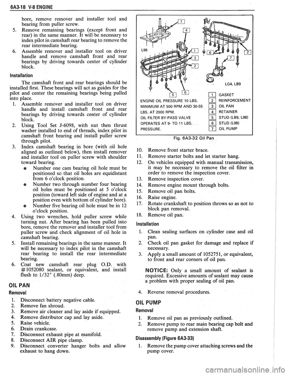
GASKET
ENGINE OIL PRESSURE 10 LBS.
1 REINFORCEMENT
MINIMUM AT 500 RPM AND 30-55
1 OIL PAN
LBS. AT 2000 RPM.
161 RETAINER
OIL FILTER BY-PASS VALVE STUD
(LB9, L98)
OPERATES
AT 9- TO 11 LBS. STUD (L98)
PRESSURE.
OIL PUMP
Fig. 6A3-32 Oil Pan
10. Remove front starter brace.
11. Remove starter bolts and let starter hang.
12. On vehicles equipped with manual transmission,
it may be necessary to remove the oil filter in
order to remove the inspection cover.
13. Remove inspection cover.
14. Remove engine mount through bolts.
15. Remove oil pan bolts.
16. Raise engine.
17. Rotate crankshaft to position throws so as not to
block pan removal.
18. Remove oil pan.
lnstallation
1.
Clean sealing surfaces on cylinder case and oil
pan.
2. Check oil pan gasket for damage and replace if
necessary.
3. Apply a small amount of 1052751, or equivalent,
to front and rear corners of oil pan.
NOTICE: Only a small amount of sealant is
required. Excessive amounts of sealant may cause
a problem with proper sealing of oil pan.
4. Reverse removal procedures.
OIL PUMP
Removal
1. Remove oil pan as previously outlined.
2. Remove pump to rear main bearing cap bolt and
remove pump and extension shaft.
Disassembly (Figure 6A3-33)
1. Remove the pump cover attaching screws and the
pump cover.
Page 560 of 1825
DRIVEABILITY AND EMISSIONS 5.OL (VIN E) 6EZ-C1-5
DIAGNOSIS
Since the ECM can have a failure which may
effect only one circuit, following the diagnostic
procedures in this section can reliably tell when a
failure has occurred in the ECM. Also,
a Code
55 in
dicates a failure of the ECM.
If a diagnostic chart indicates that the ECM
connections or ECM is the cause of a
problem,and the
ECM is replaced, but does not correct the problem, one
of the following may be the reason:
e
connections. - The diagnostic chart will say "ECM
Connections or ECM". The terminals mav have to be
removed from the connector in order to check them
properly.
@ The ECM or PROM is not correct for the
. - The incorrect ECM or PROM may cause
a malfunction and may or may not set a code.
. - This means that
time the system is
being checked. In this case, refer to the "Symptoms"
portion of the manual and make a careful physical
Solenoids and relays are turned "ON" and "OFF" by
the ECM, using internal electronic switches called
"Drivers".
A shorted solenoid, relay coil, or harness in a
GMP4 computer will not damage the ECM,
but will cause the circuit and controlled
component to be inoperative. When the
circuit fault is not present or has been
repaired, the "Quad-Driver" will again
operate in a normal manner due to it's fault
protected design. If a fault has been repaired
in a circuit controlled
by a "Quad-Driver", the
original
ECM should be reinstalled and the
circuit checked for proper operation.
ECM
replacement will not be necessary if the
repaired circuit or component now operates
correctly.
534636 or BT8405 testers or equivalent provide a
fast, accurate means of checking for a shorted coil or a
short to battery voltage.
e , - Although the
PROM rarely
fails,it operates as part of the ECM.
Therefore, it could be the cause of the problem.
Substitute a known good PROM.
o . - After the
ECM is replaced, the system should be rechecked for
proper operation. If the diagnostic chart again
indicates the ECM is the problem, substitute a known
good ECM. Although this is a rare condition, it could
happen. The
components or circuits and the codes or
charts, related to them are:
@ Code 55 indicates a failure of the ECM.
@ PROM - Code 51.
@ Coolant Temperature Sensor - CHARTS 14 -
15.
@ MAP sensor - CHART 33 or 34. To check the
sensor with no code set, use CHART
C-1D.
e TPS - CHARTS 21 or 22.
e PIN switch - CHART C-1A
@ Crank Signal - CHART C-1B
@ O2 Sensor - CHARTS 13,44,45.
@ VSS - CHART 24 and in TCC System.
e Distributor - CHART 42 and in EST system.
@ Distributor - Chart and in the EST system.
ECM
A faulty ECM will be determined in the diagnostic
charts, or by a Code 55.
PROM
An incorrect or faulty PROM, which is part of the
ECM, may set a Code 51.
ECM INPUTS
All of the sensors and input switches can be
diagnosed by the use of a "Scan" tool. Following is
a
short description of how the sensors and switches can
be diagnosed by the use of "a Scan" tool. The
"Scan"
tool can also by used to compare the values for a
normal running engine with the engine you're
diagnosing.
Coolant Temperature Sensor
A "Scan" tool displays engine temp. in degrees
centigrade. After the engine is started, the
temperature should rise steadily to about
90°C, then
stabilize when thermostat opens.
A fault in the
coolant sensor circuit should set a Code 14 or 15. The
code charts also contain a chart to check for sensor
resistance values relative to temperature.
MAT Sensor
A "Scan" tool displays temperature of the air
entering the engine and should read close ambient air
temperature, when engine is cold, and rise
as
underhood temperature increases. If the engine has
not been run for several hours (overnight), the MAT
sensor temperature and coolant temperature should
read close to each other.
Page 723 of 1825
6E3-Cl-4 2.8L (VIN S) DRIVEABILITY AND EMISSIONS
BarWNeutral Switch (Auto Only)
The ParWNeutral (PIN) switch indicates to the
ECM when the transmission is in Park or Neutral.
This information is used for the TCC and the IAC
valve operation.
Important
Vehicle should not be driven with ParWNeutral
switch disconnected as idle quality will be affected
and a possible false Code
24 (VSS).
See Section "$A" for more information on the PIN
switch, which is part of the neutrallstart and backup
light switch assembly.
NC '"n" Signal
This signal tells the ECM that the A/C selector
Switch is turned on, and that the pressure cycling
switch is closed. The ECM uses this to adjust the idle
Speed when the air conditioning is working.
If this signal is not available to the ECM, idle may
be rough, especially when the
A/C compressor cycles.
The voltage at ECM terminal "B8" should equal
battery voltage when
AIC is requested and the
pressure cycling switch is closed.
The signal at
B8 will cause the ECM to turn on the
A/C clutch by energizing the A/C relay.
Distributor Reference Signal
The distributor sends a signal to the ECM to tell it
both engine RPM and crankshaft position. See EST
System for further information.
To read the codes, use a "Scan" tool or ground the
diagnostic terminal with the engine not running and
the ignition on. The "Service Engine Soon" light will
flash Code 12 three times and
then flash each code
stored in memory three times. All codes stored in
memory would have been read when Code 12 was
flashed again. No new codes can be stored when in the
Diagnostics Mode (diagnostics lead grounded).
This
eliminates confusion while the system is being worked
on. To clear the codes from memory:
@ Ignition off
@ Remove fuse located in a weather proof holder
located near the battery for 30 seconds.
Since the ECM can have
a failure which may
effect only one circuit, following the Diagnostic
Procedures in this section will determine which circuit
has a problem and where it is. If
a diagnostic chart indicates that the ECM
connections or ECM is the cause of
a problem and the
ECM is replaced, but does not correct the problem, one
of the following may be the reason:
€9
connections. - The diagnostic chart will say "ECM
connections or ECM. The terminals may have to be
removed from the connector in order to check them
properly.
@ The ECM or PROM is not correct for the
application.
- The incorrect components may cause a
malfunction and may or may not set a code.
@ The problem is intermittent. - This means that
the problem is not present at the time the system is
being checked. In this case, refer to the "Symptoms"
portion of the manual and make a careful physical
inspection of all portions of the system involved.
@ Shorted solenoid, relay coil, or harness. -
Solenoids and relays are turned "ON" and "OFF" by
the
ECM,using internal electronic switches called
"Drivers". Each driver is part of
a group of four called
"Quad-drivers". Failure of one driver can damage any
other driver in the set.
Solelloid and relay coil
resistance must measure more than 20 ohms. Less
resistance will cause early failure of the ECM
"driver". A shorted solenoid, relay coil, or harness,
with a GMP4 computer, will not damage the ECM, but
will cause the component to be inoperative.
Before replacing an ECM, be sure to check the coil
resistance of all solenoids and relays controlled by the
ECM. See ECM wiring diagram for the
solenoid(s)
and relay(s) and the coil terminal identification.
534636 or BT 8405 testers or equivalent provide
a fast, accurate means of checking for a shorted coil or
a short to battery voltage.
@ The PROM may be faulty. - Although these
rarely fail, it operates as part of the ECM. Therefore,
it could be the cause of the problem. Substitute a
known good PROM.
@ The replacement ECM may be faulty. - After the
ECM is replaced, the system should be rechecked for
proper operation. If the diagnostic chart again
indicates the ECM is the problem, substitute
a known
good ECM. Although this is a rare condition, it could
happen.
ECM
A faulty ECM will be determined in the diagnostic
charts or
by a Code 55.
PROM
A faulty PROM may result in a Code 51.
Page 738 of 1825
DRIVEABILITY AND EMISSIONS 2.8L (VIN 5) 6E3-CZ-3
Fuel Cutofl Mode
No fuel is delivered by the injector when the
ignition is "OFF". This prevents dieseling. Also, fuel
is not delivered if no reference pulses are seen from
the distributor, which means the engine is not
running. This prevents flooding.
Fares Control System Components
The fuel control system is made up of the following
parts:
e Fuel Injectors
@ Throttle Body
e Fuel pump relay
@ Fuel Pressure Regulator
@ Fuel Rail
Basic System Operation
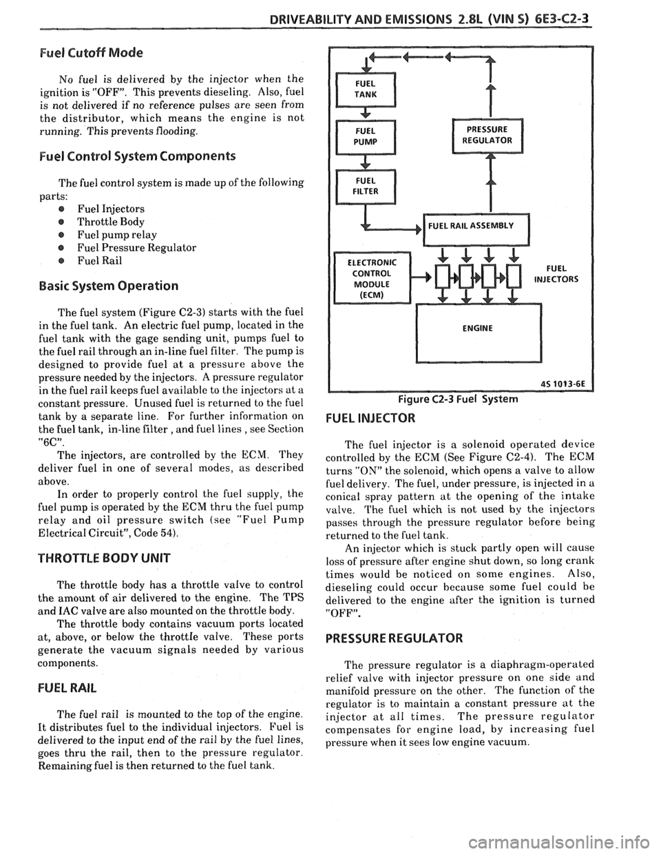
The fuel system (Figure C2-3) starts with the fuel
in the fuel tank. An electric fuel pump, located in the
fuel tank with the gage sending unit, pumps fuel to
the fuel rail through an in-line fuel filter. The pump is
designed to provide fuel at a pressure above the
pressure needed by the injectors. A pressure regulator
in the fuel rail keeps fuel available to the injectors at a
constant pressure. Unused fuel is returned to the fuel
tank by a separate line. For further information on
the fuel tank, in-line filter
, and fuel lines , see Section
"6C".
The injectors, are controlled by the ECM. They
deliver fuel in one of several modes, as described
above. In order to properly control the fuel supply, the
fuel pump is operated by the ECM thru the fuel pump
relay and oil pressure switch (see
"Fuel Pump
Electrical Circuit", Code 54).
THROTTLE BODY UNIT
The throttle body has a throttle valve to control
the amount of air delivered to the engine. The TPS
and
IAC valve are also mounted on the throttle body.
The throttle body contains vacuum ports located
at, above, or below the
throttIe valve. These ports
generate the vacuum signals needed by various
components.
FUEL RAIL
The fuel rail is mounted to the top of the engine.
It distributes fuel to the individual injectors. Fuel is
delivered to the input end of the rail by the fuel lines,
goes thru the rail, then to the pressure regulator.
Remaining fuel is then returned to the fuel tank.
Figure C2-3 Fuel System
FUEL INJECTOR
The fuel injector is a solenoid operated device
controlled by the ECM (See Figure C2-4). The ECM
turns
"ON" the solenoid, which opens a valve to allow
fuel delivery. The fuel, under pressure, is injected in a
conical spray pattern at the opening of the intake
valve. The fuel which is not used by the injectors
passes through the pressure regulator before being
returned to the fuel tank.
An injector which is stuck partly open will cause
loss of pressure after engine shut down, so long crank
times would be noticed on some engines. Also,
dieseling could occur because some fuel could be
delivered to the engine after the ignition is turned
"OFF".
PRESSURE REGULATOR
The pressure regulator is a diaphragm-operated
relief valve with injector pressure on one side and
manifold pressure on the other. The function of the
regulator is to maintain a constant pressure at the
injector at all times. The pressure regulator
compensates for engine load, by increasing fuel
pressure when it sees low engine vacuum.
Page 879 of 1825
6E3-C1-4 5.0L (VIN F) & 5.7L(VIN 8) DRIVEABILITY AND EMISSIONS
See Section "8A" for more information on the PIN
switch, which is part of the neutrallstart and backup
light switch assembly.
NC "ON" Signal
This signal tells the ECM that the NC selector
switch is turned "ON", and that the pressure cycling
switch is closed. The
ECM uses this to adjust the idle
speed when the air conditioning is working.
[f this signal is not available to the ECM, idle may
be rough, especially when the NC compressor cycles.
The voltage at ECM terminal "B8" should equal
battery voltage on a
C60 system and about 5 volts on a
C68 option, when
NC is requested and the pressure
cycling switch is closed.
Distributor Reference Signal
The distributor sends a signal to the ECM to tell it
both engine rpm and crankshaft position. See ignition
system Section
"C4" for further information.
DIAGNOSIS
To read the codes, use a "Scan" tool or ground the
diagnostic terminal with the engine not running and
the ignition "ON". The "Service Engine Soon" light
will flash Code 12 three times and then flash each code
stored in memory three times. All codes stored in
memory would have been read when Code 12 was
flashed again. No new codes can be stored when in the
diagnostics mode (diagnostics lead grounded). This
eliminates confusion while the system is being worked
on.
To clear the codes from memory:
@ Ignition "OFF".
@ Disconnect battery pigtail, located near the
battery, for 30 seconds.
Since the ECM can have a failure which may
affect only one circuit, following the diagnostic
procedures in this section will determine which circuit
has a problem and where it is.
If a diagnostic chart indicates that the
ECM
connections or ECM is the cause of a problem,and the
ECM is replaced, but does not correct the problem, one
of the following may be the reason:
-
@ There is a problem with the ECM terminal
connections.
- The diagnostic chart will say ECM
connections or ECM. The terminals may have to
be removed from the connector in order to check
them properly.
@ The ECM, or Mem-Cal is not correct for the
application.
- The incorrect components may cause
a malfunction and
may or may not set u code.
@ The problem is intermittent. - 'l'his means that the
problem is not present at the time the system is
being checked. In
this case, refer to the "Symptoms" portion
of the
manual and make a careful physical inspection
of
all portions of the system involved.
@ Shorted solenoid, relay coil, or harness. - Solenoids
and relays are turned
"ON" and "OFF" by the
ECM, using internal electronic switches called
"Drivers".
A shorted solenoid, relay coil, or harness in a
GMP4 computer will not damage the ECM,
but will cause the circuit and controlled
component to be inoperative. When the
circuit fault is not present or has been
repaired, the
"Quad-Driver" will again
operate in a normal manner due to it's fault
protected design.
If a fault has been repaired
in a circuit controlled by a "Quad-Driver",
the original ECM should be reinstalled and
the circuit checked for proper operation.
ECM replacement will
not be necessary if the
repaired circuit or component now operates
correctly.
534636 or BT 8405 testers or equivalent provide a
fast, accurate means of checking for a shorted coil
or a short to battery voltage.
@ The Mem-Cal may be faulty. - Although these
rarely fail, it operates as part of the ECM.
Therefore, it could be the cause
of the problem.
Substitute a known good Mem-Cal.
@ The replacement ECM may be faulty - After the
ECM is replaced, the system should be rechecked
for proper operation. If the diagnostic chart again
indicates the ECM is the problem, substitute a
known good ECM. Although this is a rare
condition, it could happen.
ECM
A faulty ECM will be determined in the diagnostic
charts.
MEM-CAL
An incorrect or faulty Mem-Cal, which is part of
the ECM, may set a Code 41 or 52. Also, be sure Mem-
Cal is fully seated and latched in the socket.
ECM INPUTS
A11 of the sensors and input switches can be
diagnosed by the use of
a "Scan" tool. Following is a
short clescription of how the sensors and switches can
he diagnosed
by the use of a "Scan" tool. The "Scan"
can also be used to compare the values for a normal
running engine with the engine you're diagnosing.
Page 890 of 1825
DRIVEABILITY AND EMISSIONS 5.OL (VIN F) & 5.7L (VIN 8) 6E3-CZ-3
Deceleration Mode
The ECM looks at changes in throttle position and
air flow to reduce the amount of fuel. When
deceleration is very fast, the ECM may shut off fuel
completely for short periods.
Battery Voltage Correction Mode
When battery voltage is low, the ECM can
compensate for the weak spark delivered by the
distributor by:
@ Increasing the amount of fuel delivered;
@ Increasing the idle rpm; and
@ Increasing ignition dwell time.
Fuel Cutoff Mode
No fuel is delivered by the injector when the
ignition is "OFF". This prevents dieseling. Also, fuel
is not delivered if no reference pulses are seen from
the distributor, which means the engine is not
running. This prevents flooding.
FUEL CONTROL SYSTEM
Basic System Operation
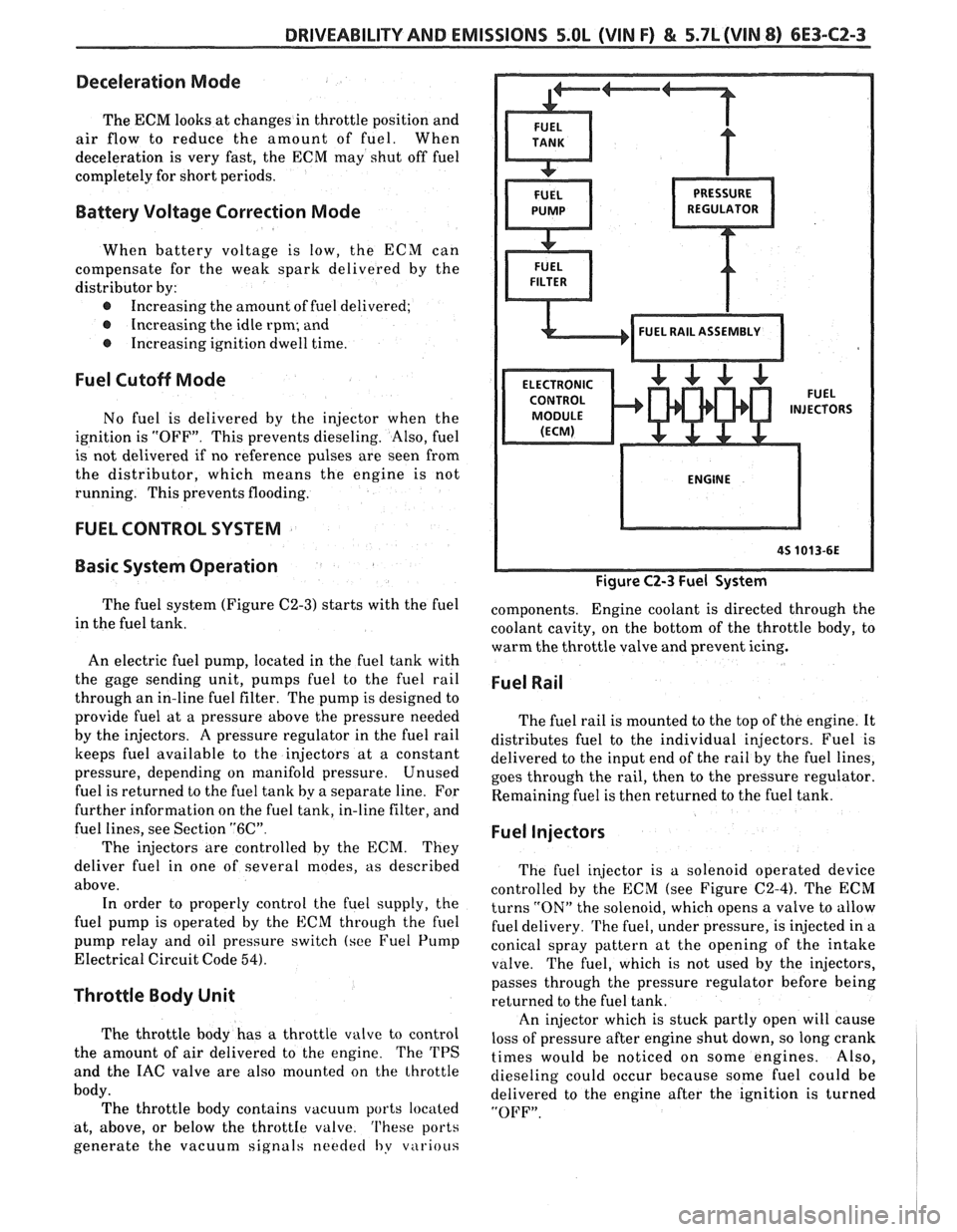
The fuel system (Figure C2-3) starts with the fuel
in the fuel tank.
An electric fuel pump, located in the fuel tank with
the gage sending unit, pumps
fuel to the fuel rail
through an in-line fuel filter. The pump is designed to
provide fuel at a pressure above the pressure needed
by the injectors. A pressure regulator in the fuel rail
keeps fuel available to the injectors at
a constant
pressure, depending on manifold pressure. Unused
fuel is returned to the fuel tank by a separate line. For
further information on the fuel tank, in-line filter, and
fuel lines, see Section
"6C".
The injectors are controlled by the ECM. They
deliver fuel in one of several modes, as described
above. In order to properly control the fuel supply, the
fuel pump is operated by the
ECM through the fuel
pump relay and oil pressure switch (see Fuel Pump
Electrical Circuit Code
54).
Throttle Body Unit
The throttle body has a throttle valve to control
the amount of air delivered to the engine. The TPS
and the IAC valve are also mounted on the throttle
body. The throttle body contains vacuum ports located
at, above, or below the
throttIe valve. 'I'hese ports
generate the vacuum signals
needed I,y v~irious
Figure C2-3 Fuel System
components. Engine coolant is directed through the
coolant cavity, on the bottom of the throttle body, to
warm the throttle valve and prevent icing.
Fuel Rail
The fuel rail is mounted to the top of the engine. It
distributes fuel to the individual injectors. Fuel is
delivered to the input end of the rail by the fuel lines,
goes through the rail, then to the pressure regulator.
Remaining fuel is then returned to the fuel tank.
Fuel Injectors
The fuel injector is a solenoid operated device
controlled by the ECM (see Figure
C2-4). The ECM
turns
"ON" the solenoid, which opens a valve to allow
fuel delivery.
The fuel, under pressure, is injected in a
conical spray pattern at the opening of the intake
valve. The fuel, which is not used by the injectors,
passes through the pressure regulator before being
returned to the fuel tank.
An injector which is stuck partly open will cause
loss of pressure after engine shut down, so long crank
times would be noticed on some engines. Also,
dieseling could occur because some fuel could be
delivered to the engine after the ignition is turned
"OFF".
Page 972 of 1825
DRIVEABILITY AND EMISSIONS - FUEL INJEC"F0N 6E-11
@ A/% "On" or "Off" r Air Management
r Engine Coolant Temwrature r Canister Purge
@ Engine crank signal r Exhaust Gas Recirculation (EGR)
@ Exhaust Oxygen(02) Sensor @ Electronic Spark Timing (EST)
r Distributor Reference @ Fuel Control
@ Crankshaft Position @ Idle Air Control (lAC)
@ Engine Speed (RPM) Transmission Converter Clutch (TCC)
Manifold Absolute Pressure (MAP)
@ Park Neutral Switch (PB) Position @ Electric Fuel Pump
r System Voltage Air Conditioning
r Throttle Position (TPS) @ Engine Cooling Fan
r Transmission Gear Position
r Vehicle Speed (VSS) @ "Service Engine Soon" Light
@ Fuel Pump Voltage @ Diagnostic Terminal (ALDL)
r Power Steering Pressure @ Data Output (ALDL)
Mass Air Flow (MAF) @ Electronic Spark Control (ESC)
@ Manifold Air Temperature (MAT) @ Early Fuel Evaporation (EFE)
r EGR Vacuum @ Idle Speed (ISC, ILC,)
@ Engine Knock (ESC)
r Differential Pressure (VAC) 6-1-87
*7S
3429- 6E
Figure
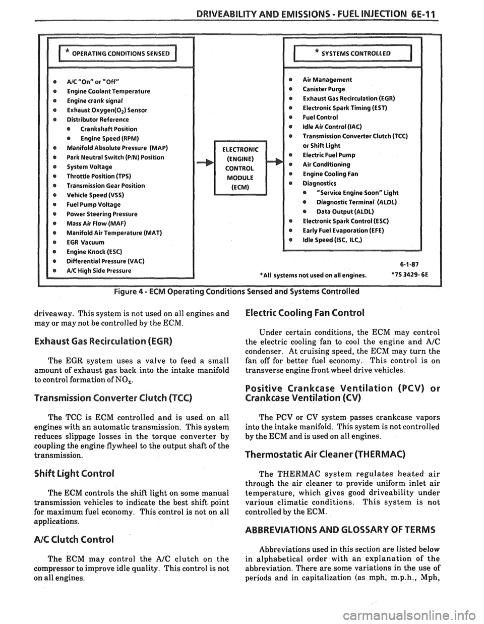
4 - ECM Operating Conditions Sensed and Systems Controlled
driveaway. This system is not used on all engines and Electric Cooling Fan Control
may or may not be controlled by the ECM.
Under certain conditions, the
ECM may control
Exhaust Gas Recirculation (ECR) the electric cooling fan to cool the engine and A/C
condenser. At cruising speed, the ECM may turn the
The
EGR system uses a valve to feed a small fan
off for better fuel economy. This control is on
amount of exhaust gas back into the intake manifold transverse
engine front wheel drive vehicles.
to control formation of
NO,.
Positive Crankcase Ventilation (PCV) or
Transmission Converter
Clutch (TCC) Crankcase Ventilation (CV)
The TCC is ECM controlled and is used on all
engines with an automatic transmission. This system
reduces slippage losses in the torque converter by
coupling the engine flywheel to the output shaft of the
transmission.
Shift Light Control
The ECM controls the shift light on some manual
transmission vehicles to indicate the best shift point
for maximum fuel economy. This control is not on all
applications.
NC Clutch Control
The ECM may control the AJC clutch on the
compressor to improve idle quality. This control is not
on all engines. The
PCV or CV system passes crankcase vapors
into the intake manifold. This system is not controlled
by the
ECM and is used on all engines.
Thermostatic Air Cleaner (THERMAC)
The THERMAC system regulates heated air
through the air cleaner to provide uniform inlet air
temperature, which gives good driveability under
various climatic conditions. This system is not
controlled by the
ECM.
ABBREVIATIONS AND GLOSSARY OF TERMS
Abbreviations used in this section are listed below
in alphabetical order with an explanation of the
abbreviation. There are some variations in the use of
periods and in capitalization (as mph,
m.p.h., Mph,