1988 PONTIAC FIERO change time
[x] Cancel search: change timePage 966 of 1825
DRIVEABILITY AND EMISSIONS - FUEL INJECTION 6E-5
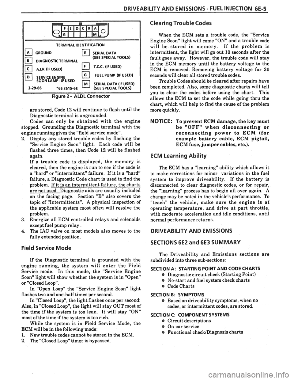
TERMINAL IDENTIFICATION
GROUND SERIALDATA
(SEE SPECIAL TOOLS)
DIAGNOSTIC TERMINAL
I.I.R. (IF USED) T.C.C. (IF USED)
SERVICE
ENGINE FUEL PUMP (IF USED)
SOON LAMP- IF USED
SERIAL DATA (IF USED) 3-29-86 *6S 2615-6E (SEE SPECIAL TOOLS)
Figure 2 - ALDL Connector
are stored, Code 12 will continue to flash until the
Diagnostic terminal is ungrounded.
Codes can only be obtained with the engine
stopped. Grounding the Diagnostic terminal with the
engine running gives the "field service mode".
2. Display any stored trouble codes by flashing the
"Service Engine Soon" light. Each code will be
flashed three times, then Code
12 will be flashed
again.
If a trouble code is displayed, the memory is
cleared, then the engine is run to see
if the code is
a "hard" or "intermittent" failure. If it is a "hard"
failure, a Diagnostic Code chart is used to find the
problem. If it is an intermittent failure, the charts
are not used. Diagnostic aids are usually included
on the facing page. Section
"B" also covers the
topic of "Intermittents".
A physical inspection of
the applicable system most often will resolve the
problem.
3. Energize all ECM controlled relays and solenoids
except fuel pump relay
.
4. The IAC valve on most models also moves to the
fully extended position.
Field Service Mode
If the Diagnostic terminal is grounded with the
engine running, the system will enter the Field
Service mode. In this mode, the "Service Engine
Soon" light will show whether the system is in "Open"
or
"Closed Loop".
In "Open Loop" the "Service Engine Soon" light
flashes two and one-half times per second.
In "Closed Loop", the light flashes once per second:
Also, in "Closed Loop", the light will stay OUT most of
the time
if the system is too lean. It will stay "ON"
most of the time if the system is too rich.
While the system is in Field Service Mode, the
ECM will be in the following mode:
1. New trouble codes cannot be stored in the ECM.
2. The "Closed Loop" timer is bypassed.
Clearing Trouble Codes
When the ECM sets a trouble code, the "Service
Engine Soon" light will come "ON" and a trouble code
will be stored in memory. If the problem is
intermittent, the light will go out
10 seconds after the
fault goes away. However, the trouble code will stay
in the ECM memory until the battery voltage to the
ECM is removed. Removing battery voltage for
30
seconds will clear all stored trouble codes.
Trouble Codes should be cleared after repairs have
been completed. Also, some diagnostic charts will tell
you to clear the codes before using the chart. This
allows the ECM to set the code while going thru the
chart, which will help to find the cause of the problem
more quickly.
NOTICE: To prevent ECM damage, the key must
be
"OFFn when disconnecting or
reconnecting power to
ECM (for
example battery cable,
ECM pigtail,
ECM fuse, jumper cables, etc.).
ECM Learning Ability
The ECM has a "learning" ability which allows it
to make corrections for minor variations in the fuel
system to improve driveability. If the battery is
disconnected to clear diagnostic codes, or for repair,
the "learning" process has to begin all over again.
A
change may be noted in the vehicle's performance. To
"teach" the vehicle, make sure the engine is at
operating temperature, and drive at part throttle,
with moderate acceleration and idle conditions, until
normal performance returns.
DRIVEABILITY AND EMISSIONS
SECTIONS
6E2 and 6E3 SUMMARY
The Driveability and Emissions sections are
subdivided into three sub-sections:
SECTION A: STARTING POINT AND CODE CHARTS
@ Diagnostic circuit check (Starting Point)
@ No-start and fuel system check charts
@ Code Charts
SECTION B: SYMPTOMS
e Based on driveability symptoms, when no
codes, or intermittent codes, are stored.
SECTION C: COMPONENT SYSTEMS
@ Circuit descriptions
@ On-car service
@ Functional checWDiagnosis charts
Page 968 of 1825
DRIVEABILITY AND EMISSIONS - FUEL INJECTION 6E-7
On engines that can be monitored in the open
mode, it allows certain parameters to be obtained
without changing the engine operating
characteristics. The parameters capable of being read
vary from engine family to engine family. Most
"Scan" tools are programmed so that the system will
go directly into the special mode
if the "open" mode is
not available.
ALDL (7 OK, or Special) Mode
(not used on
all engines)
In this mode, all information incorporated into a
specific
engine and ECM is obtainable. However, in
this mode the system operating characteristics are
modified as follows.
@ "Closed Loop" timers are bypassed
EST (spark) is advanced
@ IAC will control engine idle to 1000 rpm I
50 rpm (if applicable)
@ On some engines, canister purge solenoid will
be enabled
@ P/N restrict functions will be disabled.
Factory Test (Back-up or 3.9 K) Mode
(TBI, Port)
In this mode, the ECM is operating on the fuel
back-up logic and is calibrated by the Calpak or Mem-
cal. These are used to control the fuel delivery
if the
ECM fails. This mode verifies that the back-up feature
is OK. The parameters that can be read on a
"Scan"
tool in this mode are not of much use for service.
"SCAN" TOOL LIMITATIONS AND USE
The "Scan" tool allows a quick check of sensors
and switches which are inputs to the ECM. However,
on some applications the data update rate makes the
tool less effective as a voltmeter when trying to detect
an intermittent which lasts for a very short time.
However, the "Scan" tool allows one to manipulate
wiring harnesses or components under the hood while
observing the "Scan" readout. This helps in locating
intermittents with the engine not running.
intermittent Conditions
for a period of time to see if there is any change in the
readings that indicates intermittent operation.
The "Scan" tool is also a useful and quick way of
comparing operating parameters of a poorly operating
engine with a known good one. For example;
A sensor
may shift in value but not set a code. Comparing with
a known good vehicle may uncover the problem.
The "Scan" tool has the ability to save time in
diagnosis and prevent the replacement of good parts.
The key to using the "Scan" tool successfully for
diagnosis lies in the technician's ability to understand
the system he is trying to diagnose as well as an
understanding of the "Scan" tool's limitations.
Therefore, the technician should read the tool
manufacturer's operating manual to become familiar
with the operation. The following information will
describe most of the "Scan" tool positions and how
they can be helpful in diagnosis.
"SCAN" TOOL POSITIONS
The following positions may not be applicable to
all engines. See the facing page
of the diagnostic
circuit check for a particular engine to decide which
positions apply to that engine.
Mode
Check with the manufacturer to determine what
the function of this mode is. In most cases it allows the
user to place the ECM in different operating modes.
Injector Pulse Width
In this position, the reading is given in
milliseconds, which is the
"ON" time that the ECM is
commanding to the
injector(s1.
Closed LoopIOpen Loop
This position will indicate whether the engine
control system is operating in "Open Loop" or "Closed
Loop". Most systems go "Closed Loop" after a certain
amount of running time, when coolant temperature is
high enough, and the oxygen sensor becomes active.
Exhaust (RichILean Indicator)
The "Scan" tool is helpful in cases of intermittent
This indicates the O2 sensor voltage at the instant operation' The can be in and observed that the data stream is sampled. If voltage is less than
while driving the vehicle under the condition where
350 mv, the value will be lean. If above 550 mv, a rich the light comes "ON" momentarily, or the engine exhaust is indicated. driveability is poor momentarily. If the problem
seems to be related to certain areas that can be
Codes checked on the "Scan" tool, then those are the
positions that should be checked while driving the
This will display any trouble codes stored in the
vehicle. If there does not seem to be any correlation
ECM memory. between the problem and any specific circuit, the
"Scan" tool can be checked on each position, watching
Page 969 of 1825
6E-8 DRIVEABILITY AND EMISSIONS - FUEL INJECTION
Throttle Position Sensor (TPO) Coolant Q~erature
Values read will be the voltage as seen by the Engine
temperature is displayed in Celsius
ECM. The voltage should be the TPS specification degrees.
After the engine is started, temperature
with the throttle closed and go up to about 5 volts should
rise steadily to about
85-95" C, then stabilize
with throttle wide open
(WOT). when the thermostat opens.
Throttle Angle
Displayed, in percent, is the amount the throttle is
open. 0% is closed throttle, 100% is wide open throttle.
Oxygen (Of) Sensor
The reading will be read out in millivolts (mv)
with a range from 1 to 999 mv. If the reading is
consistently below 350 (350 mv), the fuel system
is
running lean as seen by the ECM; and if the reading is
consistently above 550 (550 mv), the system is
running rich.
In this position, information is used for assembly
verification only. PROM ID is useful only when the
vehicle
is equipped with the original ECM and PROM
or Mem-Cal.
Reading displays engine rpm. It is often useful if
extra reference pulses are suspected. A sudden high
rpm indication while at a steady throttle would
indicate electrical interference
(EMI) in the reference
circuit. This interference
is usually caused by ECM
wires too close to ignition secondary wires or an open
distributor ground circuit.
Displayed is vehicle speed, useful in checking TCC
application speed or speedometer accuracy.
MAF
This displays the amount of air passing the Mass
Air Flow
(MAF) sensor, in grams per second. It is
useful when comparing the airflow between a problem
vehicle and a known good one. Normal readings at
idle are about
4 to 8 grams. If a MAF code is set, this
reading will display the ECM default value.
This display should be the same as MAF when
there are no failures in the MAP sensor circuit. When
an MAF code is set, however, this value will not
change, and will indicate the
grn/sec that the failure
has detected.
Manifold Air Temperature (MAT) Sensor
This displays temperature of the intake manifold
air. It should read close to ambient air temperature
when the engine is cold, and rise as underhood and
engine temperatures increase.
Manifold Absolute Pressure (MAP)
The MAP sensor produces a low signal voltage
when manifold pressure is low (high vacuum) and a
high voltage when the pressure is high (low vacuum).
With the ignition "ON" and the engine stopped,
I
the manifold pressure is equal to atmospheric
pressure, and the signal voltage will be high. This 1
information is used by the ECM as an indication of
vehicle altitude and is referred to as BARO.
Comparison of this
BARO reading with a known good
vehicle with the same sensor is a good way to check
accuracy of a "suspect" sensor
*. Readings should be
the same
+ .4 volt. I
* A MAP sensor has a colored plastic insert visible I I
in the connector cavity. Sensors with the same insert I
color are identical in calibration. The harness I
I
electrical connector color also should be the same as 1 the sensor insert color.
I Vacuum (Differential Pressure) Sensor
The vacuum sensor produces a low signal voltage
when manifold vacuum is low, and a high voltage
when the vacuum is high.
With the ignition "ON" and the engine stopped,
there is no vacuum, so the voltage is low (under
1
volt). With the engine idling the vacuum is high so the
voltage is high (over
3 volts).
A vacuum sensor has a colored plastic insert
visible in the connector cavity. Sensors with the same
insert color are identical in calibration. The harness
electrical connector color also should be the same as
the sensor insert color.
This displays barometric pressure. The ECM uses
this information to adjust for altitude and pressure.
This value will vary depending on barometric
pressure and altitude. Some vehicles use a dedicated
bar0 sensor, while others take a MAP reading before
the engine is started, and at various times during
engine operation.
Page 970 of 1825
DRIVEABILITY AND EMISSIONS - FUEL INJECTION 6E-9
ParWNelatral Switch IAC (Idle Air Control)
The indication in this mode may vary with This system is used to control engine idle speed to
manufacturer so the type of reading for a particular the desired rpm, for different operating conditions. In
tool should be checked in the operator's manual. The this mode, the numbers will indicate the position to
important thing is that the the reading changes state which
the ECM has moved the valve pintle. The ECM
(switches) when the gear selector is moved from moves
the IAC in counts, or steps, and the number of
paridneutral to drive or reverse. these counts are displayed on a "Scan" tool.
"Trque Convertor Clutch (TCC)
In this position, the tool will indicate when the
TCC has been commanded by the ECM to turn "ONJ'.
This does not necessarily mean that the clutch was
engaged but only that the
ECM grounded the circuit
internally. The best way to determine if the clutch has
engaged is to monitor engine rpm when the TCC
comes "ON".
EGR (Duty Cycle)
The EGR system uses a valve to feed a small
amount of exhaust gas back into the intake manifold
to control formation of NO,. Like all ECM outputs, the
"Scan" tool only indicates that the ECM has
commanded the function, and does not indicate that
the function has really happened.
EGR Position
This indicates the position of the EGR pintle.
Integrator and Block Learn
Normal readings for these positions are around
128. If higher, it indicates that the ECM is adding fuel
to the base fuel calculation because the system is lean,
and if the numbers are below 128, the ECM is taking
out fuel from the base calculation because the system
is rich. The integrator gives short term corrective
action, while the block learn portion (which is a long
term correction) will only change if the integrator has
seen a condition which lasts for a calibrated period of
time.
Block Learn Multiplier (BLM) Cell - or -
Block Learn Memory (BLM)
There are up to sixteen different cells,
corresponding to ranges of rpm and engine load
(indicated by MAF or MAP signals), and other
conditions, such as
A/C or P/N switch "ON" or "OFF",
etc. The ECM learns how much adjustment is needed
in each cell, and retains it in memory, so that the
adjustment will immediately be made when the
engine operates in that cell (or
rpmlload range). This
parameter will display what cell the ECM is currently
using for the fuel calculation.
Desired RPM
This indicates the rpm to which the ECM is trying
to control the idle.
Shift Light
This displays "yes" when the ECM is commanding
the shift light to turn "ON".
PPSW (Pump Prime Switch)
This is the voltage on the fuel pump feed circuit.
The ECM will adjust fuel injector base pulse width
from this voltage value rather than from battery
voltage.
NC Request
The state of the A/C signal line to the ECM is
shown. It should read "yes" whenever the
IVC is
requested.
NC Clutch
"ON" is displayed when the ECM has commanded
the
A/C clutch "ON".
Knock Retard
This indicates the number of degrees the ECM is
retarding the electronic spark timing (EST).
Knock Signal
This displays a "yes" when knock is detected by
the ECM, and a "no" when knock is not detected.
Battery Voltage
This displays the battery voltage detected at the
ECM ignition input.
Fan
"ON" is displayed when the cooling fan has been
commanded "ON".
Page 1117 of 1825
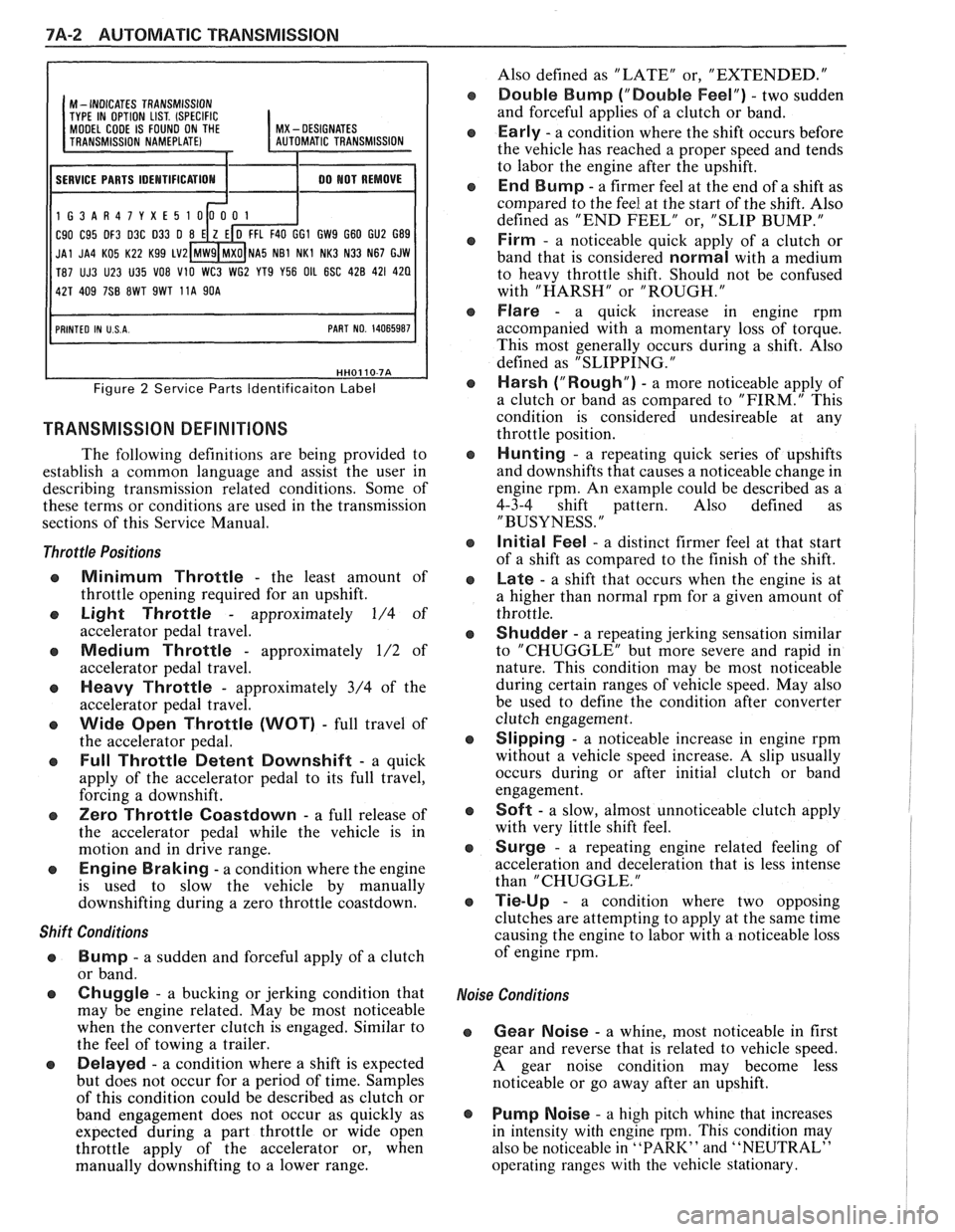
7A-2 AUTOMATIC TRANSMISSION
I I
M - INDICATES TRANSMISSION
TYPE IN OPTION LIST. (SPECIFIC MODEL CODE IS FOUND ON THE I MX - DESIGNATES
11 SERVICE PARTS IDEMTIFICATIOM I 1 00 MOT REMOVE I
1G3AR47YXE5
C90 C95 DF3 D3C 033 0 GI GW9 G60 GU2 G89
JAl JA4 KO5 K22 Kg9 LV2 NA5 NB1 NKl NK3 N33 N67 GJW
T87 UJ3 U23 U35
VO8 V10 WC3 WG2 YT9 Y56 OIL 6SC 428 421 420
Figure 2 Service Parts ldentificaiton Label
TRANSMISSION DEFINITIONS
The following definitions are being provided to
establish a common language and assist the user in
describing transmission related conditions. Some of
these terms or conditions are used in the transmission
sections of this Service Manual.
Throttle Positions
Minimum Throttle - the least amount of
throttle opening required for an upshift.
Light Throttle - approximately 1/4 of
accelerator pedal travel.
Medium Throttle - approximately 1/2 of
accelerator pedal travel.
Heavy Throttle - approximately 3/4 of the
accelerator pedal travel.
Wide Open Throttle (WOT) - full travel of
the accelerator pedal.
Full Throttle Detent Downshift - a quick
apply of the accelerator pedal to its full travel,
forcing a downshift.
Zero Throttle Coastdown - a full release of
the accelerator pedal while the vehicle is in
motion and in drive range.
Engine Braking - a condition where the engine
is used to slow the vehicle by manually
downshifting during a zero throttle coastdown.
Shift Conditions
'a Bump - a sudden and forceful apply of a clutch
or band.
Q Chuggle - a bucking or jerking condition that
may be engine related. May be most noticeable
when the converter clutch is engaged. Similar to
the feel of towing a trailer.
e Delayed - a condition where a shift is expected
but does not occur for a period of time. Samples
of this condition could be described as clutch or
band engagement does not occur as quickly as
expected during a part throttle or wide open
throttle apply of the accelerator or, when
manually downshifting to a lower range. Also
defined as "LATE" or, "EXTENDED."
Double Bump ("Double Feel") - two sudden
and forceful applies of a clutch or band.
Early - a condition where the shift occurs before
the vehicle has reached a proper speed and tends
to labor the engine after the upshift.
End Bump - a firmer feel at the end of a shift as
compared to the feel at the start of the shift. Also
defined as "END FEEL" or, "SLIP BUMP."
Firm - a noticeable quick apply of a clutch or
band that is considered
normal with a medium
to heavy throttle shift. Should not be confused
with "HARSH" or "ROUGH."
Flare - a quick increase in engine rpm
accompanied with a momentary loss of torque.
This most generally occurs during a shift. Also
defined as "SLIPPING.
"
Harsh ("Rough") - a more noticeable apply of
a clutch or band as compared to "FIRM." This
condition is considered undesireable at any
throttle position.
Hunting - a repeating quick series of upshifts
and downshifts that causes a noticeable change in
engine rpm. An example could be described as a
4-3-4 shift pattern. Also defined as
"BUSYNESS.
"
Initial Feel - a distinct firmer feel at that start
of a shift as compared to the finish of the shift.
Late - a shift that occurs when the engine is at
a higher than normal rpm for a given amount of
throttle.
Shudder - a repeating jerking sensation similar
to "CHUGGLE" but more severe and rapid in
nature. This condition may be most noticeable
during certain ranges of vehicle speed. May also
be used to define the condition after converter
clutch engagement.
Slipping - a noticeable increase in engine rpm
without a vehicle speed increase.
A slip usually
occurs during or after initial clutch or band
engagement.
Soft - a slow, almost unnoticeable clutch apply
with very little shift feel.
Surge - a repeating engine related feeling of
acceleration and deceleration that is less intense
than "CHUGGLE.
"
Tie-Up - a condition where two opposing
clutches are attempting to apply at the same time
causing the engine to labor with a noticeable loss
of engine rpm.
,e Conditions
Gear Noise - a whine, most noticeable in first
gear and reverse that is related to vehicle speed.
A gear noise condition may become less
noticeable or go away after an upshift.
Pump Noise - a high pitch whine that increases
in intensity with engine
rpm. This condition may
also be noticeable in
"PARK" and "NEUTRAL"
operating ranges with the vehicle stationary.
Page 1389 of 1825
AIR CONDITIONING: AIR DELIVERY I g
667, ELECTRONIC
TROUBLESHOOTING
HINTS
Try the following checks before doing System
Diagnosis.
1. Check for vacuum to the vacuum tank at the
BLACK Hose from the engine vacuum
source and at the VIOLET Rose to the
AIC
Vacuum Solenoid Module.
Check the operation of the Temperature
Valve by setting the Temperature Selector
to COLD and then moving it to ROT.
Observe that the valve moves through its
full range each time the Temperature Selec-
tor is changed from one end of the range to
the other. If the valve is not fully closing or
opening, check that the valve is free to move
and that none of the linkage is binding.
3. Check that Heater Water Bypass Valve
operates in MAX
AIC Mode.
Go to the AIC System Check in 8A-62 for a
guide to normal operation of the Air
Delvery
System.
Go to System Diagnosis
in this section for
diagnostic tests.
SYSTEM DIAGNOSIS
Engine warm and running at idle.
If air flow does not come from the proper
outlets under one or more operating modes,
at least one of the air valves is not moving to
the proper position.
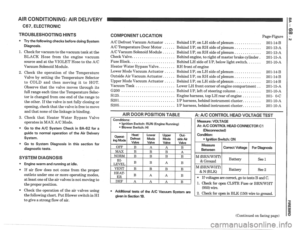
@ Check the operation of the air valves using
the following chart. Put Blower switch in
HI
to give a strong flow of air.
COMPONENT LOCATION Page-Figure
AIC Defrost Vacuum Actuator ..... Behind IIP, on LH side of plenum .............
AIC Temperature Door Motor ...... Behind IIP, on RH side of plenum. ............
AIC Vacuum Solenoid Module ...... Behind IIP, on RH side of plenum. ............
Check Valve. .................... Behind engine, to right of master brake cylinder.
Fuse Block.
..................... Behind LH side of IIP, below light switch. ......
Neater Water Bypass Valve. ....... RH front of engine
Lower Mode Vacuum Actuator
..... Behind IIP, on LH side of plenum .............
Outside Air Vacuum Actuator. ..... Behind IIP, on RH side of plenum. ............
Upper Mode Vacuum Actuator ..... Behind IIP, on LH side of plenum .............
.. Vacuum Tank ................... Lower LH front corner of engine compartment
6200
.......................... Behind IIP, left of steering column ............
S125. .......................... Engine harness, top LH rear of engine .........
........ S201. .......................... IIP harness, behind instrument cluster.
........ S205. .......................... IIP harness, behind instrument cluster.
(Disconnected)
Condition:
IgnEon Swgch: ON
AIR DOOR POSITION TABLE A: AIC CONTROL HEAD VOLTAGE TEST
Measure
Between I Correct Vdtage / For Diagmsk I
Conditions: ignition Switch: RUN (Engine Running)
Blower Switch: HI
I"(BRNIWIFDI & Ground Battery ( See1 I
Measure: VOLTAGE
At:
A/C CONTROL HEAD CONNECTOR 61
I I
@ If voltages are correct, go to tests B and C.
(Continued on facing page)
Mdifional tests of the AIC Vacum System are
(950) wire.
2- ~hd for op in BLK (150) rrire to given in Seclion 1B.
Page 1397 of 1825
WARNINGS AND ALARMS: CHIMES
GlRGUlT OPERATION
The Warnings and Alarms System sounds a
chime to bring attention to one or more of
several conditions. These conditions are:
1) the
lights are on and the Ignition Switch is not in
RUN, BULB TEST, or START;
2) the Igni-
tion key is in the Ignition Switch when the
driver's door is open; and
3) the seatbelt is un-
buckled when the Ignition Switch is in RUN,
BULB TEST, or START.
Voltage is applied at all times through the
STOP
HAZ Fuse to terminal B, to power the
solid state Audio Alarm Assembly.
IGNITION KEY VVARNING
Voltage is applied to the Audio Alarm As-
sembly by the STOP HAZ Fuse. Whenever the
key is in the Ignition Switch and the Ignition
Switch is in LOCK, OFF, or ACCY with the
driver's door open, terminal C of the module is
grounded. This sounds the alarm.
LIGHTS-ON WARNING
When the Light Switch is in HEAD or
PARK, voltage
is applied to the Audio Alarm
Assembly. When the Ignition Switch
is in
RUN, BULB TEST, or START, voltage is
applied through the Gages Fuse to the module.
These two voltages are sensed and the alarm is
not sounded.
When the Ignition Switch is not in RUN,
BULB TEST, or START, the Gages Fuse loses
voltage. The Audio Alarm Assembly senses the
change. If voltage is still available from the
Light Switch, the Lights-On Warning alarm
will sound. The alarm can be turned off by
turning the Light Switch to the OFF setting.
The module no longer senses voltage from the
Light Switch, so the alarm does not sound.
SEATBELT WARNING
With the Ignition Switch in RUN, BULB
TEST, or START, voltage is applied through
the Gages Fuse to the Audio Alarm Assembly.
With the driver's
seatbelt unbuckled, terminal
H of the module is grounded through the Seat-
belt Switch. The FASTEN BELTS Indicator
always goes on for about
5 seconds when the
Ignition Switch is set to RUN, BULB TEST,
or START. The Fasten Belts Chime, however,
only sounds if the
seatbelt is unbuckled and
the Ignition Switch
is in RUN, BULB TEST
or START
Page 1428 of 1825
INSTRUMENT PANEL: DIGITAL CLUSTER n 23 rn E
ClRCUlT OPERATION
The Instrument Cluster uses a microprocessor
to develop data for fuel supply, coolant tem-
perature, oil pressure, voltage, engine rpm, and
vehicle speed. The Digital Cluster also contains
an Odometer, Warning Indicators, and an Audi-
ble Alarm. The Audible Alarm signals low oil
pressure, high temperature, low or high voltage,
and low fuel.
With the Ignition Switch in RUN, voltage is
applied through the GAGES Fuse to the Battery
Power inputs of the Instrument Cluster. With the
Light Switch in PARK or HEAD, voltage is ap-
plied at all times to the Lights On Dim Input.
The car's speed is displayed in mph or
krnh by
selecting either English or Metric with the
En-
glishNetric selector switch.
Gages and Audible Alarm
With the Ignition Switch in RUN, voltage is
applied through the GAGES Fuse to the Battery
Power Input terminal. With the Light Switch in
PARK or HEAD, voltage is applied at all times
to the Lights On Dim Input.
Fuel Display
The Fuel Display Sender provides a signal to
the cluster that is related to fuel level. With a
full tank the resistance is 90 ohms, and with an
empty tank the resistance is less than
1 ohm.
The microprocessor converts this signal and
activates a 12 segment bar graph which dis-
plays the fuel level. When the bar graph fuel
gage display changes from two segments to
one, the Audible Alarm beeps briefly.
Oil Pressure Display
The Oil Pressure Sender, with a resistance of
0 to 90 ohms, sends a signal to the cluster that is
related
to oil pressure. At zero pressure (0 PSI),
resistance is 0 ohms, and at maximum pressure
(80 PSI), resistance is approximately 90 ohms.
The microprocessor converts the signal and
activates a 12 segment bar graph which dis-
plays the oil pressure. When the bar graph
changes from two segments to one segment
(approximately
4 PSI), the Audible Alarm
beeps briefly.
kmperature Display
The Coolant Temperature Sender sends a sig-
nal to the Instrument Cluster that is related to
coolant temperature. Coolant Temperature
Sender resistance drops from 1,365 ohms at
100°F
(38"C), to 55 ohms at 260°F (127°C). The
temperature display is a bar graph display with
12 segments. When the bar graph changes to all
segments activated (hot coolant temperature),
the Audible Alarm beeps.
Volts Display
The microprocessor in the gages module re-
ceives a signal from the Battery Power Input ter-
minal. This signal activates the 12 segment bar
graph volts display. The volts gage ranges from 8
volts
(1 segment lit) to 18 volts (all segments lit).
Under idling and normal driving conditions, 7 or
8 segments are lit. When the volts gage displays
less than
4 segments or more than 12 segments,
the Audible Alarm beeps.
Tachometer
The Thchometer displays engine speed in rpm.
Voltage pulses are taken from the
Ignition Sys-
tem and sent to the Tachometer. Solid state cir-
cuits process these pulses into a signal that con-
trols the Tachometer display. The Tachometer
responds to the frequency of the voltage pulses,
the number of pulses in a second. This increases
with engine speed. The
'Pdchometer Filter in the
circuit rounds off the pulses and removes voltage
spikes.
Speedometer
The digital Speedometer is operated by an
electronic circuit. The Vehicle Speed Sensor, lo-
cated in the Transmission, generates an AC volt-
age whose frequency is proportional to the speed
of the vehicle. This goes to the Vehicle Speed
Sensor Buffer and then to the Speedometer cir-
cuit board in the Instrument Cluster. The solid
state circuit processes this signal into a control
signal for the Speedometer display.
Odometer
The digital Odometer display is operated by an
electronic circuit. The Vehicle Speed Sensor, lo-
cated in the Transmission, generates an
AC volt-
age whose frequency is proportional to miles
(kilometers) traveled. This goes to the Buffer
and then to the Odometer circuit board in the
Instrument Cluster. The solid state circuit
processes this signal into a control signal for
the Odometer display. Distance Data is stored
in
NV RAM Chip.