1988 PONTIAC FIERO audio
[x] Cancel search: audioPage 1651 of 1825

9A-2 RADlO SYSTEMS - AND ANTENNAS
external radio system problems before removing the
radio for repair:
1. Turn ignition to the accessory position and turn
radio on.
2. On AM-FM radios, if the radio is dead on FM
but the AM plays normally, the radio should be
removed for repair. (The reverse of this condition
does not necessarily call for radio removal).
3. On combination radio/tape units, if the radio
operates properly but the tape player does not,
the unit should be removed for repair. (The
reverse of this condition does not necessarily call
for
radio/tape removal.)
Always determine the exact nature of the radio
problem as an aid to diagnosis. Knowing whether
the condition is intermittent or constant, whether
it occurs with engine
offor running, and whether
it occurs with car parked or moving will help to
pinpoint the problem.
Radio diagnostic information is in Section
8A.
FIXED ANTENNA
Testing For Good Ground of Antenna Mounting
and Connections
Poor grounding of the power antenna, either at
the antenna mounting or at any other connection in the
antenna/lead-in system, can result in seriously reduced
radio performance.
A poor ground can be a reason for
excess ignition noise in
AM reception, or erratic audio.
To check for a poor ground of the antenna,
perform the following:
1. Fully lower antenna.
2. Disconnect antenna motor electrical connector.
3. Remove escutcheon from fender.
4. Attach alligator clip to upper end of antenna to
act as antenna. Leave other end of clip
unattached.
5. Tune radio for weak AM station or signal which
is dependent on clip,
i.e., clip attached, station is
present; clip removed, no station.
6. Remove clip.
7. Ground upper end of antenna to fender
(preferably with knife blade, very short jumper
wire, etc.).
8. If radio station is not received, then the antenna
grounds are good. If the station is still present or
stronger, a poor ground or no ground connection
is present in the system.
Possible ground loss points are:
s Antenna upper mounting (screws loose,
paint overspray, etc.)
e coaxial connector at antenna not tight or
corroded. (Remove to inspect inside the
connector for corrosion.)
e Coaxial connector at radio not tight or
corroded.
e Quick connect connector corroded.
Checking Antennas
Unplug antenna lead-in at back of radio and plug
a test antenna into radio. Make sure test antenna base
is grounded to the car chassis and keep hands off of the
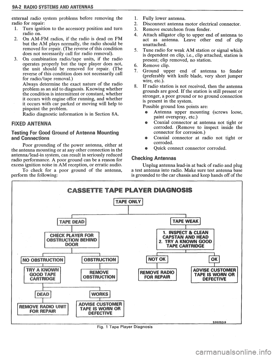
CASSEmE TAPE PLAYER DIAGNOSIS
1. INSPECT I& CLEAN
CAPSTAN
AND HEAD . TRY A KNOWN 600
ADVISE CUSTOMER
TAPE IS WORN QR DEFECTIVE
Fig. 1 Tape Player Diagnosis
Page 1652 of 1825

RADIO SYSTEMS AND ANTENNAS 9A-3
antenna. Check radio reception in an area away from
reception. If reception is OK, problem exists with
electrical interferences. These include tall buildings,
antenna and/or its lead-in cable. If reception is still
metal structures, power lines, fluorescent lighting, and
poor, refer to Section
8A.
power tools. Tune to high and low ends of the dial on
both AM and FM checking weak and strong station
reception. If reception is OK, problem exists with
antenna and/or its lead-in cable. If reception is still
poor, refer to Section
8A.
Checking Lead-In Cables
Figure 2
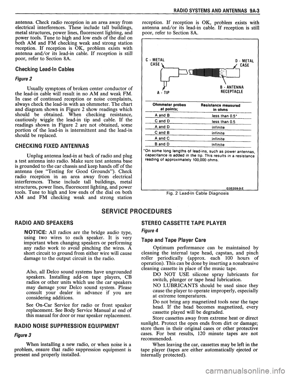
Usually symptons of broken center conductor of
the lead-in cable will result in no AM and weak FM.
In case of continued reception or noise complaints,
always check the lead-in with an ohmmeter. The chart
and diagram shown in Figure
2 show readings which
should be obtained. When checking resistance,
cautiously wiggle the lead-in tip and cable. If the
readings shown in Figure
2 are not obtained, some
portion of the lead-in is intermittent and the lead-in
should be replaced.
CHECKING FIXED ANTENNAS
Unplug antenna lead-in at back of radio and plug
a test antenna into radio. Make sure test antenna base
is grounded to the car chassis and keep hands off of the
antenna (see "Testing for Good Grounds"). Check
radio reception in an area away from electrical
interferences. These include tall buildings, metal
structures, power lines, fluorescent lighting, and power
tools. Tune to high and low ends of the dial on both
AM and FM checking weak and strong station
less than 0.5'
less than 0.5
'On some long lengths
of lead-ins, such as power antennas,
capacitance is added in the tip. This results in a resistance
reading of approximately 100,000 ohms.
Fig. 2 Lead-In Cable Diagnosis
SERVICE PROCEDURES
RADIO AND SPEAKERS
STEREO CASSETTE TAPE PLAYER
NOTICE: All radios are the bridge audio type,
using two wires to each speaker. It is very
important when changing speakers or performing
any radio work to avoid pinching the wires. A
short circuit to ground from either wire will cause
damage to the output circuit in the radio.
Also, all Delco sound systems have ungrounded
speakers. Installing add-on tape players, CB
radios or other units which use the car speakers
may damage your Delco sound system. Please
consult your dealer in advance if you are
considering additions.
See On-Car Service for radio or front speaker
replacement. See Body Service Manual at end of
this manual for door or rear speaker replacement. Figure 4
Tape and Tape Player Care
Optimum performance can be maintained by
cleaning the internal tape head, capstan, and pinch
roller periodically (approx. each 100 hours of
operation). This can be done by inserting a nonabrasive
cleaning cassette in place of the music tape.
DO NOT USE silicone spray lubricants for
switch, plunger or tape head lubrication.
NO LUBRICANTS should be used since they
cause the player to operate improperly, especially
at extreme temperatures.
Do not bring any magnetized tools near the tape
head. If the head becomes magnetized, every
cassette played will be degraded.
Store cassettes away from extreme heat or direct
RADIO NOISE SUPPRESSION EQUIPMENT sunlight. Protect the open ends from dirt or damage;
store them in their original cases or other protective
Figure 3 cases. For best results, 120 minute tapes are not
recommended.
When installing a new radio, or when noise is a
When leaving the car, cassettes may be left in the
problem, ensure that radio suppression equipment is
tape player (tapes are either automatically ejected or
present and properly installed.
internally protected).
Page 1658 of 1825

RADIO SYSTEMS AND ANTENNAS 9A.9
This radio cannot be used on cars without
steering wheel controls. When removed from the
car and reinstalled, the radio will be dead and
LOC will appear on the graphic display. Press
MUTE on the steering wheel to reactivate the
radio.
To Operate the Tape Player:
(NOTE: The following controls are located on
the receiver.)
inserting f ape
Insert cassette into door marked AUTO
REVERSE, so exposed edge of tape enters first.
This turns tape player on and disables the radio.
Tape Bias
When the "CrO" button is lighted, it is set for
chrome or metal tapes; press and the light will go
out (for normal bias tapes).
Reversing Sides
Press program button PROG to play other side
of tape. When end of tape is reached, it
automatically reverses direction and plays the
other side.
NOTE: When lighted arrow located below tape
door points "up," selections listed on the top side of
the tape are being played; when arrow points
"down,"the bottom side is being heard.
Fast Forward
Press FWD button to activate; press PROG to
return to playing speed.
Fast Reverse
Press REV button to activate; press PROG to
return to playing speed.
Music Search
Press SEEK to automatically find the next
selection. Press REPT to repeat the selection
being played.
To Eject Tape
Press EJECT.
NOTE: Power button must be "on." Tape ejects
and radio becomes operative. (It is not nesessary
to eject tapes when leaving car, since internal
pressure is automatically released when ignition
is turned "off.")
For best results,
120 minute tapes are not
recommended.
"Receives
C-QUAMO AM stereo broadcasts.
Most AM stereo stations across the country broadcast
in
C-QUAMO, but some do not. Check with your
local station for compatibility in your area.
C-QUAMO is a Registered Trademark of
Motorola, Inc.
ON-GAR SERVICE
RADIO RECEIVER
Figures 606 and 607
Remove or Disconnect
1. Negative battery cable.
2. Radio/AC-Heater console trimplate.
3. Four (4) radio retaining screws.
4. Pull radio straight out.
5. Power, speaker and antenna connectors. Remove
radio.
6. Transfer attaching parts (clips, brackets, etc.) to
new radio if unit is to be replaced.
Install or Connect
To replace, reverse removal procedure.
RADIO STEERING WHEEL CONTROLS
Refer to Section 3B4 for removal procedure.
AUDIO AMPLIFIER
Figure 610
Remove or Disconnect
5. Two (2) harness connectors.
6. Three (3) attaching screws and remove bracket
from amplifier.
Install or Connect
Reverse removal procedure to reinstall.
RADIO SUPPRESSION EQUIPMENT
When installing a new radio, or when noise is a
problem, insure that radio suppression equipment is
present and properly installed.
FRONnSPEAKER
Figure 606
Remove or Disconnect
1. Instrument panel pad (see Section 8C).
2. Four (4) screws holding speaker in instrument
panel carrier.
3. Lift speaker out of instrument panel. Disconnect
wiring.
Install or Connect
1. Negative battery cable. Reverse removal procedure to install.
2. Right side
instrument close out panel.
3. Two (2) amplifier bracket to instrument panel REAR SPEAKER; SUB-WOOFER SPEAKER
screws.
Rear speakers are mounted in the rear quarter
4. Lower audio amplifier and bracket out of trim panel. See Section
2N in the body portion of this
instrument panel. manual for complete details
of replacement.
Page 1662 of 1825

RADIO SYSTEMS AND ANTENNAS 9A.13
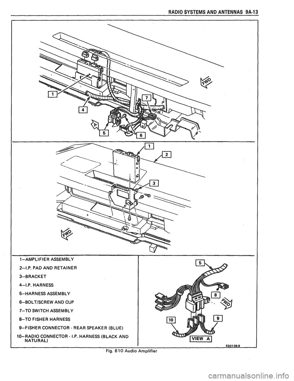
1-AMPLIFIER ASSEMBLY
2-I.P. PAD AND RETAINER
3-BRACKET
4-I.P. HARNESS 5-HARNESS ASSEMBLY
6-BOLTISCREW AND CUP
7-TO SWITCH ASSEMBLY
8-TO FISHER HARNESS
9-FISHER CONNECTOR
- REAR SPEAKER (BLUE)
10-RADIO CONNECTOR
- I.P. HARNESS (BLACK AND
NATURAL)
Fig.
6 10 Audio Amplifier