1988 PONTIAC FIERO remove seats
[x] Cancel search: remove seatsPage 1342 of 1825
DEFOGGER
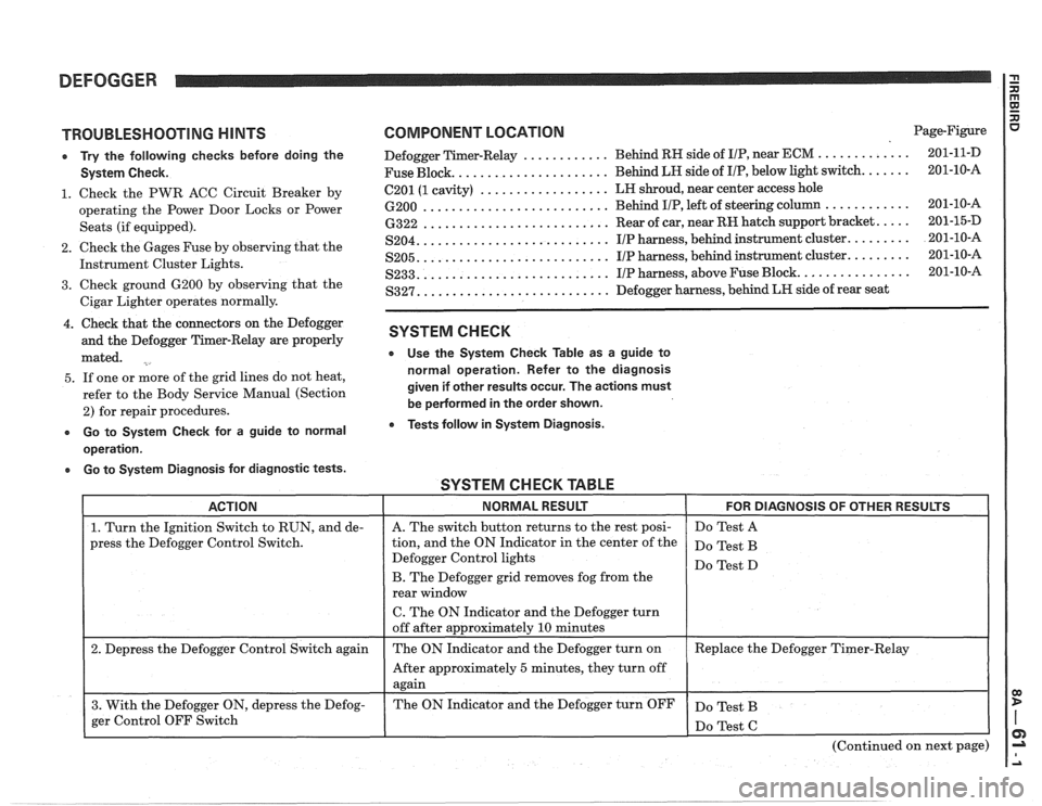
TROUBLESHOOTING HINTS
e Try the following checks before doing the
System Check.
1. Check the PWR ACC Circuit Breaker by
operating the Power Door Locks or Power
Seats (if equipped).
2. Check the Gages Fuse by observing that the
Instrument Cluster Lights.
3. Check ground 6200 by observing that the
Cigar Lighter operates normally.
4. Check that the connectors on the Defogger
and the Defogger Timer-Relay are properly
mated.
5. If one or more of the grid lines do not heat,
refer to the Body Service Manual (Section
2) for repair procedures.
e Go to System Check for a guide to normal
operation.
a Go to System Diagnosis for diagnostic tests.
COMPONENT LOCATION Page-Figure
............ ............. Defogger Timer-Relay Behind
RH side of IIP, near ECM 201-1 1-D
..................... Fuse Block. Behind LH side
of I/P, below light switch. ...... 201-10-A
.................. 6201 (1 cavity) LH
shroud, near center access hole
.......................... 6200 Behind IIP, left of steering column ............ 201-10-16
.......................... 6322 Rear of car, near RH hatch support bracket. .... 201-15-D
.......................... S204. IIP harness, behind instrument cluster. ........ 201-10-A
.......................... S205. IIP harness, behind instrument cluster. ........ 201-10-A
.......................... S233. IIP harness, above Fuse Block. ............... 201-10-A
.......................... S327. Defogger harness, behind LR side of rear seat
SYSTEM CHECK
e Use the System Check Table as a guide to
normal operation. Refer to the diagnosis
given if other results occur. The actions must
be
pedormed in the order shown.
Tests follow in System Diagnosis.
SYSTEM CHECK TABLE -- -
ACTION NORMAL RESULT FOR DIAGNOSIS OF OTHER RESULTS
1. Turn the Ignition Switch to RUN, and de-
press the Defogger Control Switch.
2. Depress the Defogger Control Switch again
3. With the Defogger ON, depress the Defog-
ger Control OFF Switch
I
A. The switch button returns to the rest posi-
tion, and the ON Indicator in the center of the
Defogger Control lights
B. The Defogger grid removes fog from the
rear window
C. The ON Indicator and the Defogger turn
off after approximately
10 minutes
The ON Indicator and the Defogger turn on
After approximately
5 minutes, they turn off
again
The ON Indicator and the Defogger turn OFF Do
Test A
Do Test B
Do Test D
Replace the Defogger Timer-Relay
Do Test B
(Continued on next page)
Page 1706 of 1825
UNDERBODY-F STYLE 3H-1
SECTION 3H
UNDERBODY
CONTENTS
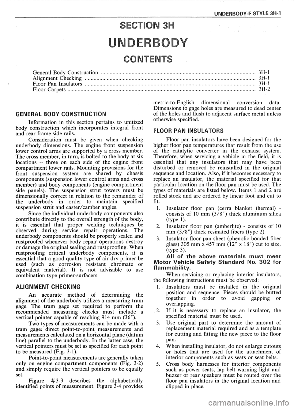
General Body Construction .......................................................................................................... 3H- 1
Alignment Checking ................................................................................................................ 3H- I
Floor Pan Insulators ...................... .. ........................................................................................ 3H- 1
Floor Carpets ................................................................................................................................. 3H-2
metric-to-English dimensional conversion data.
Dimensions to gage holes are measured to dead center
GENERAL BODY CONSTRUCTION of the holes and flush to adjacent surface metal unless
Information in this section pertains to unitized otherwise specified.
body construction which
incorporates integral front
and rear frame side rails. FLOOR PAN INSULATORS
Consideration must be given when checking
underbody dimensions. The engine front suspension
lower control arms are supported by a cross member.
The cross member, in turn, is bolted to the body at six
locations
-- three on each side of the engine front
compartment lower rails. Mounting provisions for the
front suspension system are shared by chassis
components (suspension lower control arms and cross
member) and body components (engine compartment
side panels). The suspension strut towers must be
dimensionally correct in relation to the remainder of
the underbody in order to maintain specified
suspension strut and
castedcamber angles.
Since the individual underbody components also
contribute directly to the overall strength of the body,
it is essential that proper welding techniques be
observed during service repair operations. The
underbody components should be properly sealed and
rustproofed whenever body repair operations destroy
or damage the original sealing and rustproofing. When
rustproofing critical underbody components, it is
essential that a good quality type of air dry primer be
used (such as corrosion resistant chromate or
equivalent material). It is not advisable to use
combination type primer-surfacers.
ALIGNMENT CHECKING
An accurate method of determining the
alignment of the underbody utilizes a measuring tram
gage. The tram gage set required to perform the
recommended measuring checks must include a
vertical pointer capable of reaching 914 mm (36").
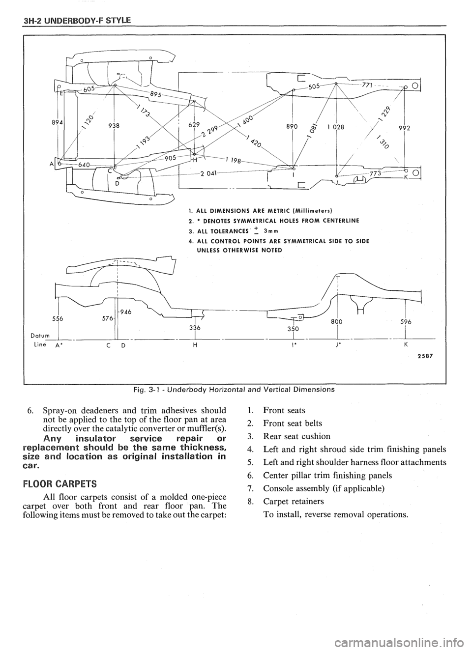
Two types of measurements can be made with
a
tram gage: direct point-to-point measurements and
measurements calculated on a horizontal
vlane (datum
line) parallel to the underbody. In the
latter case, the
vertical pointers must be set as specified for each point
to be measured (Fig. 3-1).
Point-to-point measurements are generally taken
only on engine compartment components (Fig. 3-2)
and simply require the vertical pointers to be equally
set.
Figure #3-3 describes the alphabetically
identified points of measurement. Figure 3-4 provides Floor
pan insulators have been designed for the
higher floor pan temperatures that result from the use
of the catalytic converter in the exhaust system.
Therefore, when servicing a vehicle in the field, it is
essential that any insulators that may have been
disturbed or removed be reinstalled in the original
sequence and location. Also, if it becomes necessary to
replace an insulator, the material specified for that
particular location on the floor pan must be used. The
types of materials are listed below. Items 1 and
2 are
rolled stock and are ordered by linear foot and cut to
fit.
1. Insulator floor pan
(cerra blanket thermal) -
consists of 10 mm (3/8") thick aluminum silica
(type 1).
2. Insulator floor pan (amberlite) - consists of 10
mm
(3/8") thick resinated fibers (type 2).
3. Insulator floor pan sheet (phenolic bonded fiber
glass)
305 mm x 457 mm (12" x 18") cut to size,
(type 3).
All of the above materials must meet
Motor Vehicle Safety Standard No. 302 for
flammability.
When servicing or replacing interior insulators,
the following instructions must be observed:
1. Insulators must be installed in the original
position and sequence. Pieces should be butted
together in order to avoid gapping or
overlapping.
2. If it is necessary to replace an insulator, the
specified material must be used.
3. Use original
part to determine the amount of
replacement material required and as a template
for cutting and fitting the new piece to the floor
pan.
4. When installing insulator, do not enlarge cutouts
or holes that are used for the attachment of
interior components such as seats or seat belts.
5. Cross body harnesses for interior components
such as power seats, lap belt warning light and
buzzer or rear speakers must be routed over the
floor pan insulators in the original location and
clipped in place.
Page 1707 of 1825
3H-2 UNDERBODY-F STYLE
Fig. 3-1 - Underbody Horizontal and Vertical Dimensions
6. Spray-on deadeners and trim adhesives should 1. Front seats
not be applied to the top of the floor pan at area
2, Front seat belts directly over the catalytic converter or muffler(s).
Any insulator service repair or 3. seat cushion
re~laeement should be the same thickness, 4. Left and right shroud side trim finishing panels size and location as original installation in
Car. 5. Left and right shoulder harness floor attachments
6. Center pillar trim finishing panels
FLOOR CARPETS 7. Console assembly (if applicable)
All floor carpets consist of a molded one-piece
*, Carpet retainers carpet over both front and rear floor pan. The
following items must be removed to take out the carpet: To
install, reverse removal operations.
Page 1785 of 1825
9H-2 SEATS - I: STYLE
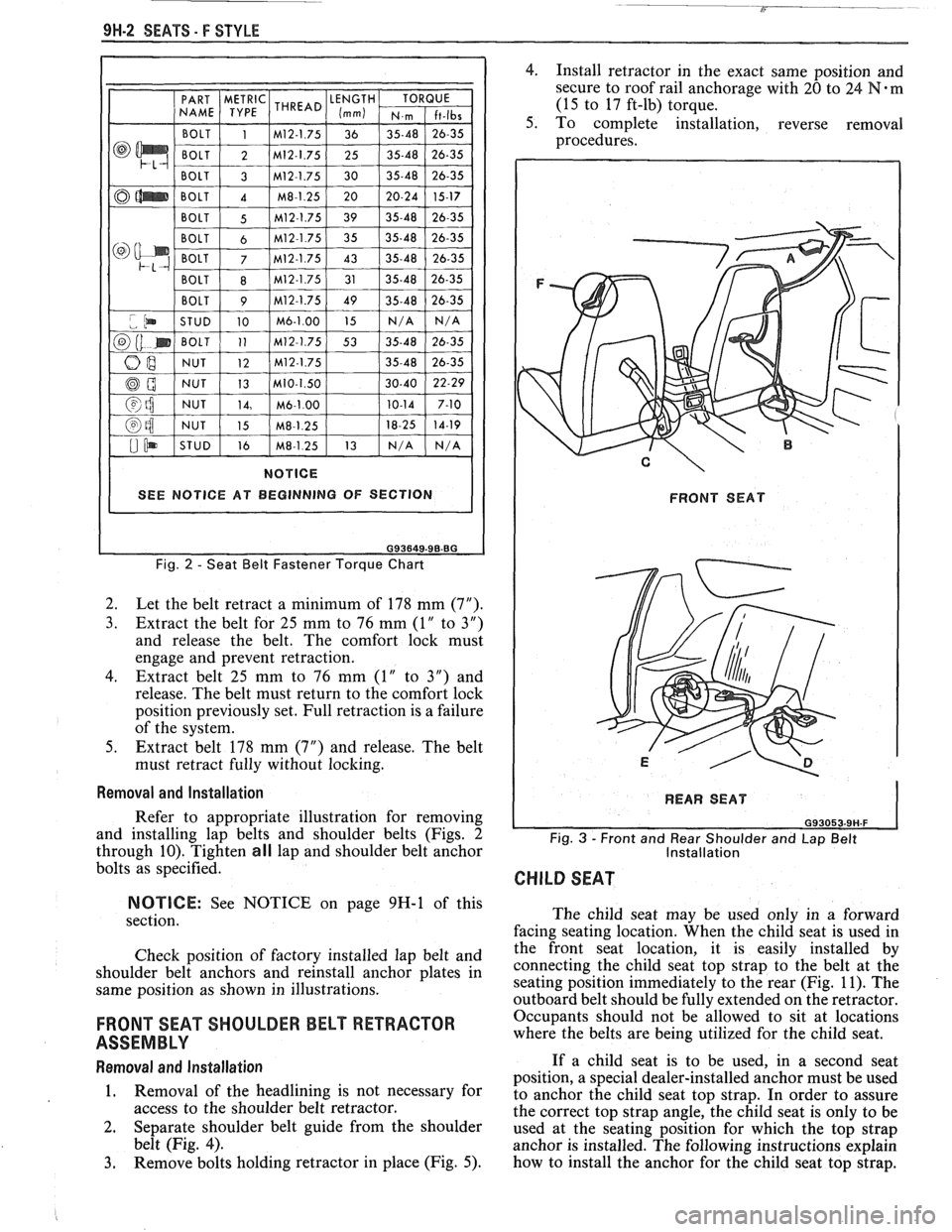
Fig. 2 - Seat Belt Fastener Torque Chart
2.
Let the belt retract a minimum of 178 mm (7").
3. Extract the belt for 25 mm to 76 mm (1" to 3")
and release the belt. The comfort lock must
engage and prevent retraction.
4. Extract belt 25 mm to 76 mm (1" to 3") and
release. The belt must return to the comfort lock
position previously set. Full retraction is a failure
of the system.
5. Extract belt 178 mm (7") and release. The belt
must retract fully without locking.
Removal and Installation
Refer to appropriate illustration for removing
and installing lap belts and shoulder belts (Figs. 2
through 10). Tighten
all lap and shoulder belt anchor
bolts as specified.
NOTICE: See NOTICE on page 9H-1 of this
section.
Check position of factory installed lap belt and
shoulder belt anchors and reinstall anchor plates in
same position as shown in illustrations.
FRONT SEAT SHOULDER BELT RETRACTOR
ASSEMBLY
Removal and Installation
1. Removal
of the headlining is not necessary for
access to the shoulder belt retractor.
2. Separate shoulder belt guide from the shoulder
belt (Fig. 4).
3. Remove bolts holding retractor in place (Fig. 5).
4. Install retractor in the exact same position and
secure to roof rail anchorage with 20 to
24 Fd-m
(15 to 17 ft-lb) torque.
5. To complete installation, reverse removal
procedures.
FRONT SEAT
I REAR SEAT 1
Fig. 3 - Front and Rear Shoulder and Lap Belt
Installation
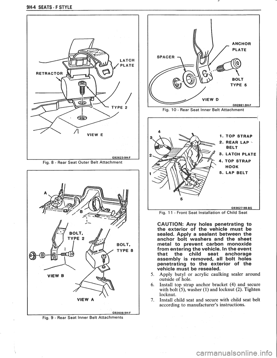
CHILD SEAT
The child seat may be used only in a forward
facing seating location. When the child seat is used in
the front seat location, it is easily installed by
connecting the child seat top strap to the belt at the
seating position immediately to the rear (Fig. 11). The
outboard belt should be fully extended on the retractor.
Occupants should not be allowed to sit at locations
where the belts are being utilized for the child seat.
If a child seat is to be used, in
a second seat
position, a special dealer-installed anchor must be used
to anchor the child seat top strap. In order to assure
the correct top strap angle, the child seat is only to be
used at the seating position for which the top strap
anchor is installed. The following instructions explain
how to install the anchor for the child seat top strap.
Page 1787 of 1825
9H-4 SEATS - F STYLE
Fig. 8 - Rear Seat Outer Belt Attachment
BOLT,
TYPE 8
TOP STRAP
REAR LAP
,,
BELT
LATCH PLATE
TOP STRAP
HOOK LAP BELT
Fig. 11 - Front Seat Installation of Child Seat
CAUTION: Any holes penetrating to
the exterior of the vehicle must be
sealed. Apply a sealant between the
anchor bolt washers and the sheet
metal to prevent carbon monoxide
from entering the vehicle. In the event
that the child seat anchorage
assembly is removed, all bolt holes
penetrating to the exterior of the
vehicle must be resealed.
5. Apply butyl or acrylic caulking sealer around
outside of hole.
6. Install top strap anchor bracket (4) and secure
with bolt
(9, washer (1) and locknut (2). Tighten
locknut.
7. Install child seat and secure with child seat belt
according to manufacturer's instructions.
Fig. 9 - Rear Seat Inner Belt Attachments
Page 1788 of 1825
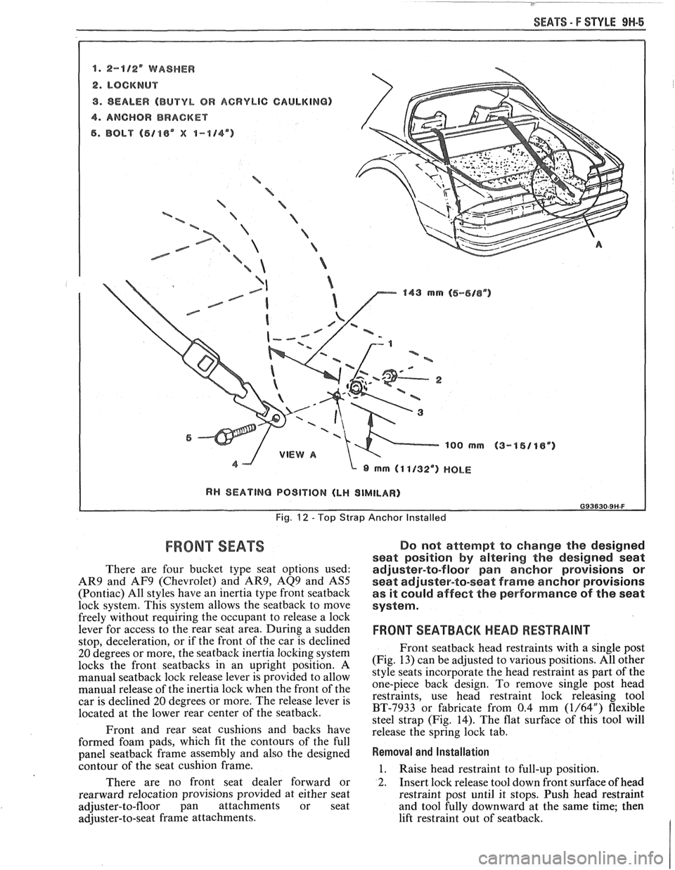
SEATS - F STYLE 9H-5
8. 2-8/2' WASHER
2. LOCKNUT
9. SEALER (BUTYL OR ACRYLIC CAULKING)
4. ANCHOR BRACKET
6. BOLT (5188" X 1-114")
a B -% ='-a
/ '%
/ e-5- B
a 143 mrn (6-616") 143 mrn (6-616")
~QO rnm 1QO rnm
I RH SEATING PO9lVlON (LH SIMILAR) I
Fig. 12 - Top Strap Anchor Installed
FRONT SEATS Do not attempt to change the designed
seat position
by altering the designed seat
There are four bucket type seat options used: adjuster-to-floor pan anchor provisions or
AR9 and AF9 (Chevrolet) and AR9, AQ9 and AS5 seat adjuster-to-seat frame anchor provisions
(Pontiac) All styles have an inertia type front seatback as it could affect the performance of the seat
lock system. This system allows the seatback to move system.
freelv without reauiring the occupant to release a lock
leve; for access to the rear seat a;ea. During a sudden
stop, deceleration, or if the front of the car is declined
20 degrees or more, the seatback inertia locking system
locks the front seatbacks in an upright position. A
manual
seatback lock release lever is provided to allow
manual release of the inertia lock when the front of the
car is declined
20 degrees or more. The release lever is
located at the lower rear center of the seatback.
Front and rear seat cushions and backs have
formed foam pads, which
fit the contours of the full
panel
seatback frame assembly and also the designed
contour of the seat cushion frame.
There are no front seat dealer forward or
rearward relocation provisions provided at either seat
adjuster-to-floor pan attachments or seat
adjuster-to-seat frame attachments.
FRONT SEATBACM HEAD RESTRAINT
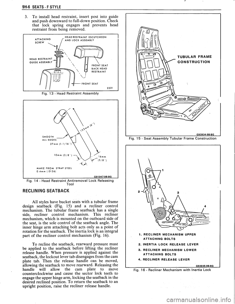
Front seatback head restraints with a single post
(Fig. 13) can be adjusted to various positions. All other
style seats incorporate the head restraint as part of the
one-piece back design. To remove single post head
restraints, use head restraint lock releasing tool
BT-7933 or fabricate from 0.4 mm
(1/64") flexible
steel strap (Fig. 14). The flat surface of this tool will
release the spring lock tab.
Removal and Installation
1. Raise head restraint to full-up position.
2. Insert lock release tool down front surface of head
restraint post until it stops. Push head restraint
and tool fully downward at the same time; then
lift restraint out of seatback.
Page 1789 of 1825
9H-6 SEATS - F STYLE
3. To install head restraint, insert post into guide
and push downward to full-down position. Check
that lock spring engages and prevents head
restraint from being removed.
HEAD RESTRAINT ESCUTCHEON
ATTACHING [AND LOCK ASSEMBLY
SCREW ,
HEAD RESTRAINT
GUIDE ASSEMBLY
Fig. 13 - Head Restraint Assembly
MAKE FROM STRAP STEEL 0.4mm 1.01561
Fig. 14 - Head Restraint Antiremoval Lock Releasing
Tool
RECLINING SEATBACK
All styles have bucket seats with a tubular frame
design
seatback (Fig. 15) and a recliner control
mechanism. The tubular frame
seatback has a single
side, recliner control mechanism. This recliner
mechanism, which is mounted on the outboard side of
the seat, is the sole control of the
seatback angle. The
inner hinge arm attaching bolt acts only as a point of
rotation for the seatback. The inertia lock is an integral
part of the recliner control mechanism (Fig.
16).
To recline the seatback, rearward pressure must
be applied to the
seatback before lifting the recliner
release handle. When pressure is applied against the
seatback, the lockout lever tab disengages from the cam
plate tab. Then the release handle can be moved,
allowing the
seatback to move rearward. Releasing the
handle will allow the cam plate to move
counterclockwise and cause the sector lock teeth to
engage the upper hinge arm, locking the
seatback in the
desired reclined position. To return the
seatback to an
upright position, raise the recliner release handle.
Fig. 15 - Seat Assembly Tubular Frame Construction
1. RECLINER MECHANISM UPPER
ATTACHING BOLTS
2. INERTIA LOCK RELEASE LEVER
3. RECLINER MECHANISM LOWER
ATTACHING BOLTS
4. RECLINER RELEASE LEVER
G93935-96-BG
Fig. 16 - Recliner Mechanism with Inertia Lock
Page 1790 of 1825
SEATS - F STYLE 9H-7
~
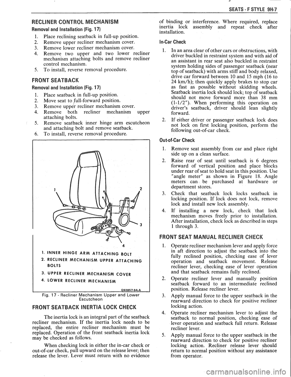
RECLINER CONTROL MECHANISM
Removal and Installation (Fig. 17)
1. Place reclining seatback in full-up position.
2. Remove
upper recliner mechanism cover.
3. Remove lower recliner mechanism cover.
4. Remove two upper and two lower recliner
mechanism attaching bolts and remove recliner
control mechanism.
5. To install, reverse removal procedure.
FRONT SEATBACK
Removal and Installation (Fig. 17)
1. Place seatback in
full-up position.
2. Move seat to full-forward position.
3. Remove upper recliner mechanism cover.
4. Remove both recliner mechanism upper
attaching bolts.
5. Remove seatback inner hinge arm escutcheon
and attaching bolt and remove seatback.
6. To
install, reverse removal procedure.
1, INNER HINGE ARM ATTACHING BOLT
2. RECLINER MECHANISM UPPER ATTACHING
3. UPPER RECLINER MECHANISM COVER
4. LOWER RECLINER MECHANISM
G92857-9A-A
Fig. 17 - Recliner Mechanism Upper and Lower
Escutcheon
FRONT SEATBACK INERTIA LOCK CHECK
The inertia lock is an integral part of the seatback
recliner mechanism. If the inertia lock needs to be
replaced, the entire recliner mechanism must be
replaced. Operation of the front
seatback inertia lock
may be checked as follows.
When checking lock in either the in-car check or
out-of-car check, pull upward on the release lever; then
release the lever. Lever must return with no evidence of
binding or interference. Where required, replace
inertia lock assembly and repeat check after
installation.
In-Car Check
1. In an area clear of other cars or obstructions, with
driver buckled in restraint system and with aid of
an assistant in rear seat also buckled in restraint
system holding sides of passenger
seatback (near
top of seatback) with arms stiff and body relaxed,
drive car forward between
10 and 15 mph (16 to
24
km/h); then quickly apply brakes to stop car
as fast as possible without skidding wheels.
Seatback inertia lock should lock; top of seatback
should not move forward more than 38 mm
(1-1/2"). When performing this operation on
driver's seatback, driver should lean slightly
forward.
2. If either driver or passenger
seatback lock does
not lock on first locking position, perform the
following out-of-car check.
Out-of-Car Check
1.
Remove seat assembly from car and place right
side up on a clean surface.
2. Raise rear of seat until seatback is 6 degrees
forward of vertical position and place blocks
under rear of seat to hold seat in this position. Use
"angle meter" as shown in Figure
18. Angle
meters can be purchased at hardware or
department stores.
3. Check that seatbaclc lock locks seatback in
locking position. If lock does not
lock, remove
lock and install new lock assembly.
4. If installing a new lock, check that lock
mechanism moves freely prior to installation.
After installation, check lock as described in steps
1 through 3.
FRONT SEAT MANUAL RECLINER CHECK
1.
Operate recliner mechanism lever and apply force
in aft direction to adjust the
seatback into the
fully reclined position, checking ease of lever
operation and
seatback movement. Release
recliner lever, checking ease of lever operation
and that
seatback remains fully reclined.
2. Operate recliner lever and manually position
seatback forward to an intermediate reclined
position. Release recliner lever.
3. Apply manual force to the upper seatback in the
rearward direction to check for positive recliner
locking action.
4. Operate recliner mechanism lever to adjust the
seatback to normal position, checking ease of
lever operation and
seatback full return. Release
recliner lever.
5. Apply manual force to the upper seatback in the
rearward direction to check for positive recliner
locking action. Recliner release lever should
return to normal position without any assistance
from operator.