1988 PONTIAC FIERO air filter
[x] Cancel search: air filterPage 552 of 1825
DRIVEABILITY AND EMISSIONS 5.OL (VIN E) 6E2-B-5
@ If the previous checks did not find the problem:
- Visually inspect ignition system for moisture,
dust, cracks, burns, etc. Spray plug wires with
fine water mist to check for shorts.
- Fuel System - Plugged fuel filter, water, low
pressure. See CHART A-7.
- Perform compression check.
- Valve timing.
- Remove rocker covers. Check for bent pushrods,
worn rocker arms, broken or weak valve springs,
worn camshaft lobes. Repair as necessary. See
Section
"6A".
If there is spray from only one injector, then,
there is
a malfunction in the injector assembly,
or in the signal to the injector assembly. The
malfunction can be isolated by switching the
injector connectors. If the problem remains with
the original injector, after switching the
connector, then the injector is defective. Replace
the iniector. If the
~roblem moves with the
injector connector, then, the problem is an
improper signal in the injector circuits. See
CHART A-3.
POOR FUEL ECONOMY
Definition: Fuel economy, as measured by an actual road test, is
noticeably lower than expected. Also, economy is noticeably lower than it
was on this car at one time, as previously shown by an actual road test.
@ CHECK: @ Visually (physically) check:
- Engine thermostat for faulty part (always open) - Vacuum hoses for splits, kinks, and proper
or for wrong heat range. See Section
"6B". connections, as shown on Vehicle Emission
- Fuel Pressure. See CHART A-7. Control Information label.
@ Check owner's driving habits. - Ignition wires for cracking, hardness, and proper
- Is A/C "ON" full time (Defroster mode "ON")? connections.
- Are tires at correct pressure? e Check ignition timing. See Emission Control
- Are excessively heavy loads being carried? Information label.
- Is acceleration too much, too often? @ Remove spark plugs. Check for cracks, wear,
- Suggest driver read "Important Facts on Fuel
improper gap, burned electrodes or heavy deposits.
Economy" in owner's manual. Repair
or replace, as necessary.
@ Perform "Diagnostic Circuit Check". @ Check compression. See Section "6A".
@ Check air cleaner element (filter) for dirt or @ Check TCC for proper operation. See CHART C-8.
being plugged. Use "Scan"
tool if available.
@ Check for proper calibration of speedometer. @ Check for dragging brakes.
Suggest owner fill fuel tank and recheck fuel
economy.
@ Check for exhaust system restriction. ,
See CHART B-1.
ROUGH, UNSTABLE, OR INCORRECT IDLE, STALLING
Definition: The engine runs unevenly at idle. If bad enough, the car may
shake. Also,
the idle may vary in rpm (called "hunting"). Either condition
may be severe enough to cause stalling. Engine idles at incorrect speed.
@ CHECK: - Vacuum leaks can cause higher than normal
- Ignition timing. See Emission Control idle.
Information label.
- EGR "ONJ', while idling, will cause roughness,
- PIN switch circuit. See CHART C-1 A. stalling, and hard starting. CHART C-7.
- For injectorb) leaking. Check fuel pressure, - Battery cables and ground straps should be clean ,
CHART A-7. and secure. Erratic voltage will cause IAC to
- IAC - See CHART C-2C.
change its position, resulting in poor idle quality.
- If a sticking throttle shaft or binding linkage - IAC valve will not move, if system voltage is
causes
a high TPS voltage (open throttle
below 9, or greater than 17.8 volts.
indication), the ECM will not control idle.
- Use "Scan" tool to determine if ECM is receiving
Monitor TPS voltage. "Scan"
andlor voltmeter AlC request signal.
should read less than
1.2 volts with throttle
closed.
Page 578 of 1825
DRIVEABILITY AND EMlSSlONS - 5.0L (VIN E) 6E2-C2-3
BASIC SYSTEM OPERATION
The fuel control system (Figure C2-2) has an
electric fuel pump, located in the fuel tank with the
gage sending unit, which pumps fuel to the TBI
through the fuel supply line, then through an in-line
fuel filter. The pump is designed to provide
pressurized fuel at about 125
kPa (18 psi). A pressure
regulator in the TBI keeps fuel available to the
injectors at a constant pressure between 62 and 90
kPa (9 and 13 psi). Fuel in excess of injector need is
returned to the fuel tank by
a separate line.
The ECM controls the injectors that are located in
the fuel meter body assembly of the TBI. The injectors
deliver fuel in one of several modes, described above.
In order to properly control the fuel supply, the
fuel pump is operated by the ECM through the fuel
pump relay and oil pressure switch (see "Fuel Pump
Electrical Circuit").
THROTTLE BODY INJECTION (TBI) UNIT
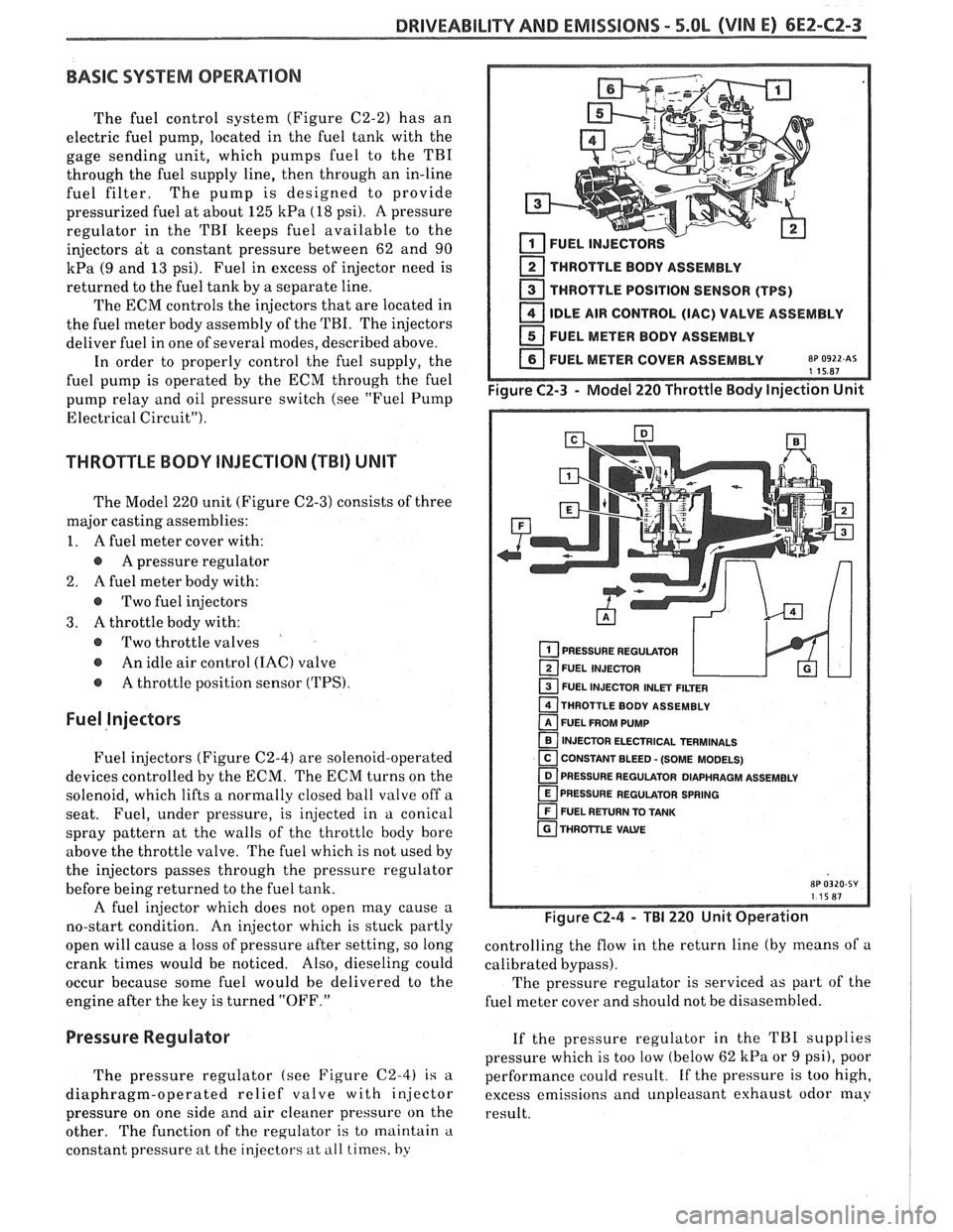
The Model 220 unit (Figure C2-3) consists of three
major casting assemblies:
1. A fuel meter cover with:
A pressure regulator
2.
A fuel meter body with:
@ Two fuel injectors
3. A throttle body with:
@ Two throttle valves
@ An idle air control (IAC) valve
@ A throttle position sensor (TPS).
Fuel Injectors
Fuel injectors (Figure C2-4) are solenoid-operated
devices controlled by the ECM. The ECM turns on the
solenoid, which lifts a normally closed ball valve off a
seat. Fuel, under pressure, is injected in a conical
spray pattern at the walls of
the throttle body bore
above the throttle valve. The fuel which is not used by
the injectors passes through the pressure regulator
before being returned to the fuel tank.
A fuel injector which does not open may cause a
no-start condition. An injector which is stuck partly
open will cause a loss of pressure after setting, so long
crank times would be noticed. Also, dieseling could
occur because some fuel would be delivered to the
engine after the key is turned "OFF."
2 THROTTLE BODY ASSEMBLY
THROTTLE POSITION SENSOR (TPS)
IDLE AIR CONTROL (IAC) VALVE ASSEMBLY
FUEL METER BODY ASSEMBLY
FUEL METER COVER ASSEMBLY
8~ 0922 AS 115R7
PRESSURE REGULATOR
FUEL INJECTOR
1 FUEL INJECTOR INLET FILTER
THROTTLE BODY ASSEMBLY
FUEL FROM PUMP
INJECTOR ELECTRICAL TERMINALS
[ CONSTANT BLEED - (SOME MODELS) - PRESSURE REGULATOR DIAPHRAGM ASSEMBLY
PRESSURE REGULATOR SPRING
FUEL RETURN TO TANK
THROTTLE
VAWE
Figure C2-4 - TBI 220 Unit Operation
controlling the flow in the return line (by means of a
calibrated bypass).
The pressure regulator is serviced as part
of the
fuel meter cover and should not be disasembled.
Pressure Regulator If the pressure regulator in the TBI supplies
pressure which
is too low (below 62 kPa or 9 psi), poor
The pressure regulator (see Figure
C2-4) is a performance could result. if the pressure is too high,
diaphragm-operated relief valve with injector excess emissions and unpleasant exhaust odor
may
pressure on one side and air cleaner pressure on the
result.
other. The function of the regulator is to maintain
'1
constant pressure at the in.jecto1.s at ill1 times, by
Page 579 of 1825
6EZ-C2-4 DRIVEABILITY AND EMISSIONS - 5.OL (VIN El
[isj FUEL METER COVER bL BODY ASSEMBLIES
1 THROTTLE BODY ASSEMBLY
1 IDLE AIR CONTROL VALVE ASSEMBLY - FILTERED AIR INLET
PlNTLE
TWRO$TLE VAWE
VACUUM PORTS - FOR ENGINE OR EMISSION
CONTROLS
8P 0319-SY 111 5W7
Figure C2-5 - ldle Air Contol System
ldle Air Control (IAC) Valve
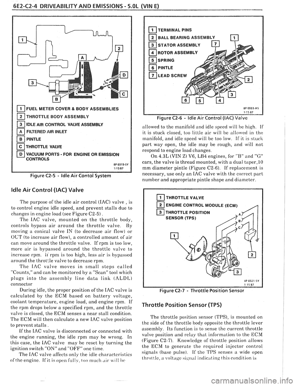
The purpose of the idle air control (IAC) valve , is
to control engine idle speed, and prevent stalls due to
changes in engine load (see Figure
C2-5) .
The IAC valve, mounted on the throttle body,
controls bypass air around the throttle valve By
moving a conical valve IN (to decrease air flow) or
OUT (to increase air flow), a controlled amount of air
can move around the throttle valve. If rpm is too low,
more air is bypassed around the throttle valve to
increase rpm.
11 rpnl is too high, less air is bypassed
around the
throt:le valve to decrease rpm.
The IAC valve moves in small steps called
"Counts," and can be monitored by
a "Scan" tool which
plugs into the assembly line data
link (ALDI,)
connector
During idle, the proper position of the IAC valve is
calculated by the ECM based on battery voltage,
coolant temperature,
ellgine load, and engine rpm. If
the rpm drops below a specified rpm, and the throttle
valve is closed, the ECM senses a near stall condition.
The ECM will then calculate a new IAC valve position
to prevent stalls.
If the IAC valve is disconnected or connected with
the engine running, the idle
rpnl may he wrong. In
this case, the
IAC valve may he reset by turning the
ignition switch "ON" and
"OFF" one time
'I'he IAC valve affects only the idle characteristics
of the engine
If it i.; ol)cltl fullv, too much ,LII. tc 111 I)(>
BALL BEARING ASSEMBLY -
STATOR ASSEMBLY
ROTOR
ASSEMBL
I
SPRING
PlNTLE
LEAD SCREW A
Figure C2-6 - ldle Air Control (IAC) Valve
allowed to the manifold and idle speed will he high. if
it is stuck closed, too little air will be
allo\verl in the
manifold, and idle speed will be too low. If it is stuck
part way open, the idle may be rough, and will not
respond to engine load changes.
On
4.3L (VIN Z) V6, LB4 engines, for "B" and "G"
cars, the valve is thread mounted, with a dual taper,lO
mm diameter pintle (Figure C2-6). If replacement is
necessary, use only an IAC valve with the correct part
number and appropriate pintle shape and diameter.
I THROTTLE VALVE
ENGINE CONTROL MODULE (ECM)
,q
THROTTLE POSITION
SENSOR (TPS)
Figure C2-7 - Throttle Position Sensor
Throttle Position Sensor (TPS)
The throttle position sensor ('I'PS), is mounted on
the side of the throttle body opposite the throttle lever
assembly. Its function is to sense the current throttle
valve position
and relkly that information to the ECM
(Figure (22-7). Knowledge of throttle position allows
lhe ECM to generate the recluired i~jector control
signals (base pulse). If the 'I'PS senses a wide open
throttle,
a voltc\ge sic,ll,~I il~tlic~ttinq this condition 13
Page 580 of 1825

DRIVEABILITY AND EMISSIONS - 5.OL (\/IN El 6EZ-CZ-5
sent to the ECM. The ECM then increases the injector
base pulse width, permitting increased fuel flow.
As the throttle valve rotates in response to
movement of the accelerator pedal, the throttle shaft
transfers this rotational movement to the
'I'PS. A
potentiometer (variable resistor) within the TPS
assembly changes its resistance (and voltage drop) in
proportion to throttle movement.
By applying a reference voltage (5.0 volts) to the
TPS input, a varying voltage (reflecting throttle
position) is available at the TPS output. For example,
approximately 2.5 volts results from a 50% throttle
valve opening (depending on TPS calibration). The
voltage output from the TPS assembly is routed to the
ECM for use in determining throttle position.
FUEL PUMP
The fuel pump is a turbine type, low pressure
electric pump, mounted in the fuel tank. Fuel
is
pumped at a positive pressure (above 62
kPa or 9 psi)
from the fuel pump through the in-line filter to the
pressure regulator in the TBI assembly Excess
fuel is
returned to the fuel tank through the fuel return line.
The fuel pump is attached to the fuel gage sender
assembly. A fuel strainer is attached to the fuel pump
inlet line and prevents dirt particles from entering the
fuel line and tends to separate
water from the fuel
Vapor lock problems are reduced when using an
electric
pump because the fuel is pushed from the tank
under pressure rather than being pulled
under
vacuum, a condition that produces vapor.
An inoperative fuel pump would cause
a. no start
condition. A fuel pump which does not provide enough
pressure can result in poor performance. (See "Fuel
System Pressure Test" procedure).
FUEL PUMP ELECTRICAL CIRCUIT
When the key is first turned "ON" without the
engine running, the ECM turns the
Fuel pump relay
"ON" for two seconds. This builds
up the fuel pressure
quickly. If the engine is not started within two
seconds, the
ECM shuts the fuel pump "OFF" and
waits until the engine starts. As soon as the engine is
cranked, the ECM turns the relay
"ON" and runs the
fuel pump.
As a backup system to the fuel pump relay, the
fuel pump can also be turned on
by the oil pressure
switch. The oil pressure sender has two circuits
internally. One operates the oil pressure indicator or
gage in the instrument cluster,
itnd the other is
anormally open switch which closes when oil pressure
reaches about 28
kPa (4 psi). If the fuel pump relay
fails, the oil pressure switch will run the fuel pump. An
inoperative fuel pump relay can result in long
cranking times, particularly if the engine is cold. The
oil pressure switch will turn on the fuel pump as soon
as oil pressure
reaches about 28 kPa (4 psi).
FUEL CONTROL
Always start with the "Diagnostic Circuit Check"
in Section
"6E2-A". This will reduce diagnosis time
and prevents unnecessary replacement of parts. The
information in this check will direct diagnosis
concerning "Engine
Crunlis But Won't Run" and the
"Fuel Control System," Section
"6E2-C2", including
diagnosis of an injector, pressure regulator,
fuel pump,
fuel
pump relay, and oil pressure switch.
Idle Air Control (IAC) Valve
A "Scan" tool reads IAC position in steps, calletl
"Counts." "0" steps indicates the ECM is commanding
the
IAC to be driven in, to a fully seiltetl position
(minimum idle air).
The higher the number steps, the
more idle air being allowed to pass
by the IAC valve.
cnose Refer to CHART C-2C for information to cliil,
the function of the IAC valve.
Driva bility
Refer to Section "B" for driveability symptoms
related to the fuel control.
ON-VEHICLE SERVICE
GENERAL SEWVICE INFORMATION
CAUTION:
e To prevent personal injury or damage to the
vehicle
as the result sf an accidental start,
disconnect and reconnect the negative
battery cable before and after service is
performed.
@ Also, catch any fuel that leaks out when
disconnecting the fuel lines, by covering the
fittings with
a shop cloth. Place the cloth in
an approved container when work is
complete.
The 'FBI unit repair procedures cover component
replacement with the unit on the vehicle,
tIowever,
throttle body replacement requires that the complete
unit
be removed from the enginc.
Page 581 of 1825
6E2-C2-6 DRIVEABILITY AND EMISSIONS - S.OL (VIN E)
PARTS
M
IDENTIFICATION
ode1 220 TBI
Screw Assembly - Fuel Mete1
Cover Attaching - Long
Screw Assembly
- Fuel Mete1
Cover Attaching - Short
Fuel Meter Cover Assembly
Gasket
- Fuel Meter Cover
Gasket
- Fuel Meter Outlet
Seal
- Pressure Regulator
Pressure Regulator
Injector
- Fuel
Filter
- Fuel lnjector lnlet
O-ring
- Fuel lnjector - Lower
O-ring
-Fuel lnjector - Upper
Washer
- Fuel lnjector
Screw Assembly - Fuel Metel
Body - Throttle Body
Attaching
Fuel Meter Body Assembly
Gasket -Throttle Body to
Fuel Meter Body
Gasket
- Air Cleaner
O-ring
- Fuel Return Line
Nut
- Fuel Outlet
O-ring
- Fuel lnlet Line
Nut
- Fuel lnlet
Gasket
- Fuel Outlet Nut
Gasket
- Fuel lnlet Nut
Screw Assembly
- TPS
Attaching Retainer
- TPS Attaching
Screw
Sensor
- Throttle Position
Plug
-Idle Stop Screw
Screw Assembly
- ldle Stop
Spring
- ldle Stop Screw
Throttle Body Assembly
Gasket
- Flange
Valve Assembly
- ldle Air
Control
Gasket
- ldle Air Control
Valve Assembly
0-Ring
- IACV
Screw Assembly
- IACV
Attaching
8P 0115-XV
Figure C2-8 - Model 220 TBI Parts Identification
Page 612 of 1825
DRIVEABILITY AND EMISSIONS 5.OL (VIN E) 6EZ-C6-1
SECTION C6
AIR INJECTION REACTION (A.I.R.) SYSTEM
CONTENTS
GENERAL DESCRIPTION ............... C6-1
PURPOSE ......................... C6-1
OPERATION ...................... C6-1
AIR CONTROL PEDES VALVE .......... C6-1
RESULTS OF INCORRECT OPERATION .... C6-2
DIAGNOSIS
........................ C6-2
OPERATIONAL CHECKS .............. C6-2
AirPump ...................... C6-2
Hoses and Pipes ................. C6-3
GENERAL DESCRIPTION
PURPOSE
The A.I.R. system helps reduce hydrocarbon (HC),
carbon monoxide (CO), and oxides of nitrogen (NO,)
exhaust emissions. It also heats up the catalytic
converter quickly on engine start-up so conversion of
exhaust gases can occur sooner.
A Dual bed converter is used. It consists of a three
way catalyst (which controls all three emissions) in
series with
a two way catalyst (which controls only HC
and
CO) both are in one housing. A pipe between the
two converters allows air to be injected into the second
(two way) converter to increase its efficiency to further
control
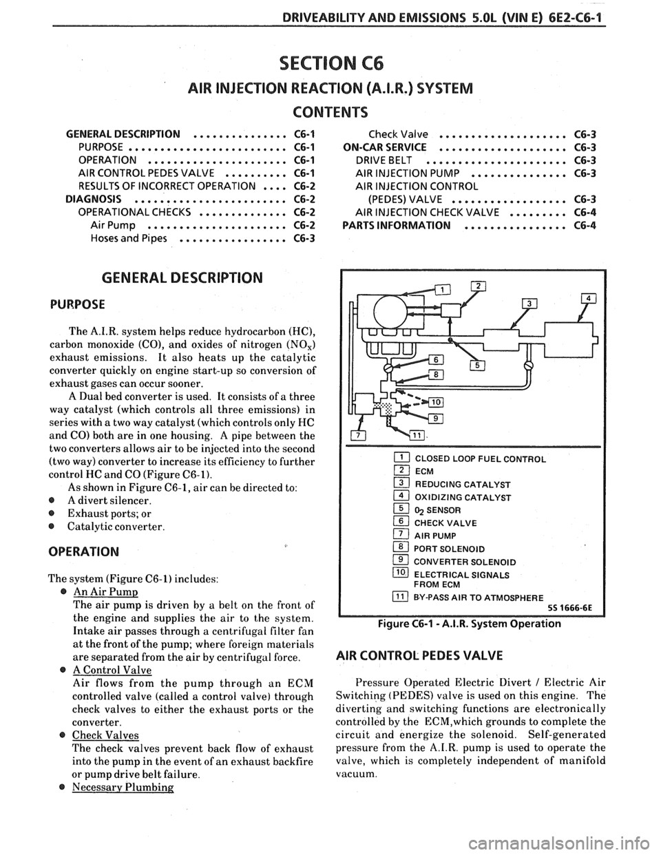
HC and CO (Figure C6-1).
As shown in Figure C6-1, air can be directed to:
@ A divert silencer.
@ Exhaust ports; or
@ Catalytic converter.
OPERATION
The system (Figure C6-1) includes:
@ An Air Pump
The air pump is driven by a belt on the front of
the engine and supplies the air to the system.
Intake air passes through a centrifugal filter fan
at the front of the pump; where foreign materials
are separated from the air
by centrifugal force.
@ A Control Valve
Air flows from the pump through an ECM
controlled valve (called a control valve) through
check valves to either the exhaust ports or the
converter.
@ Check Valves
The check valves prevent back flow of exhaust
into the pump in the event of an exhaust backfire
or pump drive belt failure.
@ Necessary Plumbing
Check Valve .................... C6-3
ON-CAR SERVICE
.................... C6-3
DRIVEBELT ...................... C6-3
AIR INJECTION PUMP ............... C6-3
AIR INJECTION CONTROL
(PEDES) VALVE
.................. C6-3
AIR INJECTION CHECK VALVE ......... C6-4
PARTS INFORMATION
................ C6-4
CLOSED LOOP FUEL CONTROL
ECM
1 REDUCING CATALYST - 1 OXlDlZlNG CATALYST
1 5 SENSOR
CHECK VALVE
1 AIR PUMP
1 PORT SOLENOID
CONVERTER SOLENOID
/ ELECTRICAL SIGNALS
FROM ECM
BY-PASS AIR TO ATMOSPHERE
Figure C6-1 - A.I.R. System Operation
AIR CONTROL PEDES VALVE
Pressure Operated Electric Divert / Electric Air
Switching (PEDES) valve is used on this engine. The
diverting and switching functions are electronically
controlled by the
ECM,which grounds to complete the
circuit and energize the solenoid. Self-generated
pressure from the A.I.R. pump is used to operate the
valve, which is completely independent of manifold
vacuum.
Page 613 of 1825
6EZ-C6-2 5.OL (VIN E) DRIVEABILITY AND EMISSIONS
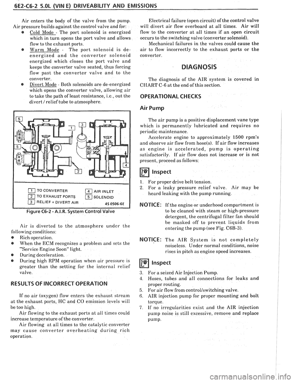
Air enters the body of the valve from the pump.
Air pressure builds against the control valve and for:
@ Cold Mode - The port solenoid is energized
which in turn opens the port valve and allows
flow to the exhaust ports.
@ Warm Mode - The port solenoid is de-
energized and the converter solenoid
energized which closes the port valve and
keeps the converter valve seated, thus forcing
flow past the converter valve and to the
converter.
@ Divert Mode - Both solenoids are de-energized
which opens the converter valve, allowing air
to take the path of least resistance,
i.e., out the
divert
/ relief tube to atmosphere.
TO CONVERTER AIR INLET
1 TO EXHAUST PORTS 1 SOLENOID / RELIEF + DIVERT AIR 45 0506-6E
Figure C6-2 - A.I.R. System Control Valve
Air is diverted to the atmosphere under the
following conditions:
@ Rich operation.
@ When the ECM recognizes a problem and sets the
"Service Engine Soon" light.
@ During deceleration.
During high RPM operation when air pressure is
greater than the setting for the internal relief
valve.
RESULTS OF lNCORRECP OPERATION
If no air (oxygen) flow enters the exhaust stream
at the exhaust ports, HC and CO emission levels will
be too high.
Air flowing to the exhaust ports at all times could
increase temperature of the converter.
Air flowing at all times to the catalytic converter
may cause converter overheating during rich
operation. Electrical failure
(open circuit) of the control valve
will divert air flow overboard at all times. Air will
flow to the converter at all times if an open circuit
occurs to the switching valve (converter solenoid).
Mechanical failures in the valves could cause the
air to flow incorrectly to the exhaust ports or the
converter.
DIAGNOSIS
The diagnosis of the AIR system is covered in
CHART C-6 at the end of this section.
OPERATIONAL CHECKS
Air Pump
The air pump is a positive displacement vane type
which is permanently lubricated and requires no
periodic maintenance.
Accelerate engine to approximately
1500 rpm's
and observe air flow from
hose(s). If air flow increases
as engine is accelerated, pump is operating
satisfactorily. If air flow does not increase or is not
present, proceed as follows:
a Inspect
1. For proper drive belt tension.
2. For a leaky pressure relief valve. Air may be
heard leaking with the pump running.
NOTICE: If the engine or underhood compartment is
to be cleaned with steam or high-pressure
detergent, the centrifugal filter fan should
be masked off to prevent liquids from
entering the pump (see Fig.
C6B-3).
NOTICE: The AIR System is not completely
noiseless. Under normal conditions, noise
rises in pitch as engine speed increases.
inspect
3. For a seized Air Injection Pump.
3. Hoses, tubes and all connections for leaks and
proper routing.
5. For air flow from control/switching valve.
6. AIR injection pump for proper mounting and bolt
torque.
7. If no irregularities exist and the AIR injection
pump noise is still excessive, remove and replace
pump.
Page 614 of 1825

DRIVEABILITY AND EMISSIONS 5.OL (VIN E) 6EZ-C6-3
CAUTION: Do Not Oil A.I.R. Pump
Hoses and Pipes
inspect
1. Hose or pipe for deterioration or holes.
2. All hoses or pipe connections, and clamp tightness.
3. Hose or pipe routing. Interference may cause
wear.
4. If a leak is suspected on the pressure side of the
system or if a hose or pipe has been disconnected
on the pressure side, the connections should be
checked for leaks with a soapy water solution.
With the pump running, bubbles will form if a
leak exists.
Check Valve
a inspect
1. A check valve should be inspected whenever the
hose is disconnected form a check valve or
whenever check valve failure is suspected.
(A
pump that had become inoperative and had shown
indications of having exhaust gases in the pump
would indicate check valve failure).
2. Blow through the check valve (toward the cylinder
head) then attempt to suck back through the check
valve Flow should only be in one
direction(toward the exhaust manifold). Replace
valve which does not operate properly.
ON-CAR SERVICE
DRIVE BELT
Remove or Disconnect
1. Inspect drive belt for wear, cracks or deterioration
and replace if required. When installing new belt,
it must be seated and fully secured in grooves of
all belt driven components.
AIR INJECTION PUMP
Remove or Disconnect
1. Hold pump pulley from turning by compressing
drive belt, then loosen pump pulley bolts.
2. Drive belt and pulley.
3. Hoses, vacuum, and electrical connections from
Air Injection Control valve.
4. Air pump mounting bolts, and pump assembly
(See Figure
C6-3).
Install or Connect
1. Air pump assembly, and tighten mounting bolts.
2. Spacer and pump pulley against centrifugal filter
fan.
3. Pump pulley bolts and tighten equally to 13 N m
(10 lb, ft).
4. Check
air injection system for proper operation
(see Chart C-6).
Figure C6-3 - Air Pump Service
AIR INJECTION CONTROL (PEDES) VALVE
Remove or Disconnect
1. Battery ground cable.
2. Adapter bolts (See Figure C6-4).
3. Air outlet hoses from valve.
4. Splash guard / cover
5. Electrical connectors and vacuum hoses from
valve.
6. Control valve.
Install or Connect
1. Control valve.
2. Electrical connectors.
3. Splash guard /cover
4. Air hoses to valve.
5. Battery ground cable.
6. Check
system operation (see
CHART C-6).