1988 PONTIAC FIERO change wheel
[x] Cancel search: change wheelPage 291 of 1825
4B-18 REAR AXLE
tire wear patterns. One indication of this condition is
"swerving on acceleration." If swerving on
acceleration is encountered, check the rear wheels for
different tire size, air pressure, or excessively different
wear patterns, and tread depths, before proceeding into
an overhaul operation.
Checking Limited-Slip Operation
1. Place transmisison
in Park position.
2. Raise
rear of vehicle until wheels are off the
ground, remove one wheel and tire assembly.
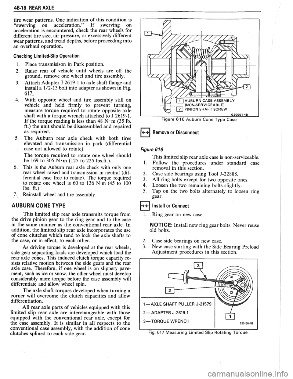
3. Attach Adapter J 2619-1 to axle shaft flange and
install a 1/2-13 bolt into adapter as shown in Fig.
617,
4. With opposite wheel and tire assembly still on
vehicle and held firmly to prevent turning,
measure torque required to rotate opposite axle
shaft with a torque wrench attached to J 2619-1.
If the torque reading is less than 48
N.m (35 lb.
ft.) the unit should be disassembled and repaired
as required.
5. The Auburn rear axle check with both tires
elevated and transmission in park (differential
case not allowed to rotate).
The torque required to rotate one wheel should
be 169 to 305
N-m (125 to 225 1bs.ft.).
6. This is the Auburn rear axle check with only one
rear wheel raised and transmission in neutral (dif-
ferential case free to rotate). The torque required
to rotate one wheel is
60 to 136 N-m (45 to 100
lbs. ft.)
7. Reinstall wheel and tire assembly.
AUBURN CONE TYPE
This limited slip rear axle transmits torque from
the drive pinion gear to the ring gear and to the case
in the same manner as the conventional rear axle. In
addition, the limited slip rear axle incorporates the use
of cone clutches which tend to lock the axle shafts to
the case, or in effect, to each other.
As driving torque is developed at the rear wheels,
side gear separating loads are developed which load the
rear axle cones. This induced clutch torque capacity re-
sists relative motion between the side gears and the rear
axle case. Therefore, if one wheel is on slippery pave-
ment, such as ice or snow, the other wheel must develop
considerably more torque before the case assembly will
differentiate and allow wheel spin.
The axle shaft torques developed when turning a
corner will overcome the clutch capacities and allow
differentiation.
All rear axle parts of vehicles equipped with this
limited slip rear axle are interchangeable with those
equipped with the conventional rear axle, except for
the case assembly. It is similar in all respects to the
conventional case assembly, with the addition of cone
clutches splined to each side gear.
INOWERVICEABLE) PINION SHAFT SCREW
Figure 6 16 Auburn Cone Type Case
Remove or Disconnect
Figure 6 16
This limited slip rear axle case is non-serviceable,
1. Follow the procedures under standard case
removal in this section.
2. Case side bearings using Tool J-22888.
3. All ring bolts except for two opposite ones.
4. Loosen the two remaining bolts slightly.
5. Tap on the two bolts alternately to loosen ring
gear.
Install or Connect
1.
Ring gear on new case.
NOTICE: Install new ring gear bolts. Never reuse
old bolts.
2. Case side bearings on new case.
3. New case starting with the Side Bearing Preload
Adjustment procedures in this section.
1 -AXLE SHAFT PULLER J-21579
2
-ADAPTER J-2619-1
3-TORQUE WRENCH
Fig.
617 Measuring Limited Slip Rotating Torque
Page 561 of 1825
6EZ-C1-6 5.OL (VIN E) DRIVEABILITY AND EMISSIONS
A failure in the MAT sensor circuit should set a Code
23 or 25. The code charts also contain
a chart to check
for sensor resistance values relative to temperature.
MAP Sensor
A "ScanJ' tool reads manifold pressure and will
display either volts or
kPa of pressure.
Key "ONJ', engine stopped, (no vacuum), MAP will
read high voltage or pressure, while at idle
(highvacuum), MAP will read low voltage or pressure.
Likewise, on accel., MAP will read high and on decel.,
will read low.
A failure in the MAP sensor, or circuit, should
result in a Code 33 or 34.
Oxygen (02) Sensor
The "Scan" tool has several positions that will
indicate the state of the exhaust gases,
02 voltage,
integrator, and block learn. See "Scan" tool position
information in the Introduction of Section
"6E".
A problem in the O2 sensor circuit should set a
Code 13 (open circuit), Code
44 (lean 02 indication),
Code
45 (rich 02 indication). Refer to the applicable
chart, if any of these codes were stored in memory.
Throttle Position Sensor (TPS)
A "Scan" tool displays throttle position in volts.
The
5.OL should read under 1.25 volts, with throttle
closed and ignition on, or at idle. Voltage should
increase at a steady rate as throttle is moved toward
WOT. The ECM has the ability to Auto-Zero the TPS
voltage, if it is below about 1.25 volts. This means
that any voltage less than 1.25 volts volts will be
determined by the ECM to be
0% throttle. Some
"Scan" tools have the ability to read the percentage of
throttle angle and should read
0%, when the throttle
is closed.
A failure in the TPS circuit or TPS, should
set a Code 21 or 22.
Vehicle Speed Sensor (VSS)
A "Scan" tool reading should closely match with
speedometer reading, with drive wheels turning. A
failure in the VSS circuit should set a Code
24.
PIN Switch
A "Scan" tool should read "ON", when in park or
neutral and "OFF", when in drive. This reading may
vary with different makes of tools. Refer to CHART C-
IA for
PIN switch diagnosis.
Power steering Pressure Switch (POPS)
A Scan" tool should read "OFF" normally, and
"ON" with high pressure. This reading may vary with
different makes of tools. Refer to CHART
C-1E for
PSPS diagnosis.
NC Request Signal
If the low pressure switch is closed and AIC is
"ON", the "Scan" tool should indicate
A/C "ON".
Distributor Reference Signal
A "Scan" tool will read this signal and is displayed
in rpm. See Section
"C4", for more information on the
Ignition System
.
Knock Signal
A "Scan" tool will indicate when the ESC module
signals the ECM that knock is present. See Section
"C5" for further information on the ESC System.
ON-CAR SERVICE
ELECTRONIC CONTROL MODULE (ECM)
Service of the ECM should normally consist of
either replacement of the ECM or a PROM change.
If the diagnostic procedures call for the ECM to be
replaced, the engine calibrator (PROM) and ECM
should be checked first to see if they are the correct
parts. If they are, remove the PROM from the faulty
ECM and install it in the new service ECM. THE
SERVICE ECM
WILL NOT CONTAIN A PROM.
Trouble Code "51" indicates the PROM is installed
improperly or has malfunctioned. When Code "51" is
obtained, check the PROM installation for bent pins or
pins not fully seated in the socket. If the PROM is
installed correctly and Code
"51" still shows, replace
the PROM.
Important
When replacing the production ECM with a
service ECM (controller), it is important to
transfer the Broadcast code and production ECM
number to the service ECM label. Please do not
record on ECM cover. This will allow positive
identification of ECM parts throughout the service
life of the vehicle.
Page 724 of 1825
DRIVEABILITY AND EMlSSlQNS 2.8L (VIN S) 6E3-C1-5
ECM Inputs
All of the sensors and input switches can be
diagnosed by the use of a "Scan" tool. Following is a
short description of how the sensors and switches can
be diagnosed by the use of "Scan".
The "Scan" can
also be used to compare the values for a normal
running engine with the engine you're diagnosing.
Coolant Temperature Sensor
A "Scan" tool displays engine temperature in
degrees centigrade. After
engine is started, the
temperature should rise steadily to about 90°C then
stabilize when thermostat opens. If the engine has not
been run for several hours (overnight) the coolant
temperature and MAT temperatures should read close
to each other. A fault in the coolant sensor circuit
should set a Code
14 or 15. The code charts also
contain a chart to check for sensor resistance values
relative to temperature.
MAF Sensor
A "Scan" tool reads the MAF value and displays it
in grams per second. Should read between 4-7 on a
fully warmed up idling engine. Values should change
rather quickly on acceleration, but values should
remain fairly stable at any given RPM. Most "Scan"
tools will have 2 positions for reading
MAE' sensor
values. (MAF
& Air Flow). Both values should read
the same if no Code 33 or 34 is set, but if a code is set,
the MAF values will be the default value and the Air
Flow parameter will lock in on the value to which the
ECM recognized the fault. A failure in the MAF
sensor or circuit should set a Code 33 or 34.
MAT Sensor
A "Scan" tool displays temperature of the air
entering the engine and should read close to ambient
air temperature when engine is cold, and rise as
underhood temperature increases. If the engine has
not been run for several hours (overnight) the MAT
sensor temperature and coolant temperature should
read close to each other. A failure in the MAT sensor
circuit should set
a Code 23 or 25. The code charts also
contain a chart to check for sensor resistance values
relative to temperature.
02 Sensor
The "Scan" has several positions that will indicate
the state of the exhaust gases,
O1! voltage, integrator,
and block learn. See "Scan" position information in
"Introduction," Section
"6E".
A problem in the O2 sensor circuit, or fuel system,
should set a Code 13 (open circuit), Code 44 (lean
indication), Code 45 (rich indication). Refer to
applicable chart if any of these codes
were stored in
memory.
TPS
A "Scan" tool displays throttle position in volts.
You should read
.55V f .08V, with throttle closed and
ignition on, or at idle. Voltage should increase at
a
steady rate as throttle is moved toward WOT.
The ECM has the ability to Auto-Zero the TPS
voltage if it is below about .7V (700
mV). This means
that any voltage less than
.7 volts will be determined
by the ECM to be
0% throttle. A failure in the TPS or
circuit should set a Code 21 or 22.
A "Scan" tools reading should closely match with
speedometer reading with drive wheels turning.
A
failure in the VSS circuit should set a Code 24.
PIN Switch
A "Scan" tool should read PIN when in Park, or
Neutral, and R-D, L, when in Drive or Overdrive.
This reading may vary with different makes of tools.
Refer to CHART
C-1A for PIN switch diagnosis.
NC Request Signal
"Scan" tool should indicate A/C request "ON,"
when A/C is requested and the pressure cycling switch
is closed.
Power Steering Pressure Switch
A "Scan" tool should read "OFF" normally and
"ON" with high pressure. This reading may vary with
different make of tools. Refer to CHART
C-1E for
PSPS diagnosis.
Reference Signal
A "ScanJ' tool will read this signal and is displayed
in rpm.
ON-CAR SERVICE
ELECTRONIC CONTROL MODULE (ECM)
Service of the ECM should normally consist of
either replacement of the ECM or a PROM change.
If the diagnostic
procedures call for the ECM to be
replaced, the engine calibrator (PROM) and ECM
should be checked first to see if they are the correct
parts. If they are, remove the PROM from the faulty
ECM
and install it in the new service ECM. THE
SERVICE ECM WILL NOT CONTAIN A PROM or
CALPAK. Trouble Code 51 indicates the PROM is
installed improperly or has malfunctioned. When
Code
51 is obtained, check the PROM installation for
bent pins or pins not fully seated in the socket. If it is
installed correctly and Code 51 still shows, replace the
PROM.
Page 880 of 1825
DRIVEABILITY AND EMISSIONS 5.OL (VIN F) & 5.7L (VIN 8) 6E3-C1-5
Coolant Temperature Sensor
A "Scan" tool displays engine temperature in
degrees centigrade. After
engine is started, the
temperature should rise steadily to about 90°C then
stabilize when thermostat opens. If the engine has not
been run for several hours (overnight), the coolant
temperature and MAT temperatures should read close
to each other.
A fault in the coolant sensor circuit
should set a Code 14 or 15. The code charts also
contain a chart to check for sensor resistance values
relative to temperature. Voltage
should increase at
a steady rate as throttle is
moved toward WOT (about 4.6 volts).
The ECM has the ability to auto-zero the TPS
voltage if it is below about
.7V (700 mV). This means
that any voltage less than
.7 volts will be determined
by the ECM to be 0% throttle. A failure in the TPS or
circuit should set a Code 21 or 22.
VSS
A "Scan" tools reading should closely match with
speedometer reading with drive wheels turning. A
failure in the VSS circuit should set a Code 24.
MAF Sensor
PIN Switch
A "Scan" tool reads the MAF value and displays it
in grams per second and should read between 4-7 on a
fully warmed up idling engine. Values should change
rather quickly on acceleration, but values should
remain fairly stable
at any given rpm. Most "Scan"
tools will have 2 positions for reading MAF sensor
values (MAF
& air flow). Both values should read the
same if no Code 33 or 34 is set, but if a code is set, the
MAF values will be the default value and the air flow
parameter will lock on the value at which the ECM
recognized the fault.
A failure in the MAF sensor or
circuit should set a Code 33 or 34.
MAT Sensor
A "Scan" tool displays temperature of the air
entering the engine and should read close to ambient
air temperature when engine is cold, and rise as
underhood temperature increases. If the engine has
not been run for several hours (overnight) the MAT
sensor temperature and coolant temperature should
read close to each other. A failure in the MAT sensor
circuit should set a Code 23 or 25. The code charts also
contain a chart to check for sensor resistance values
relative to temperature.
02 Sensor
The "Scan" has several positions that will indicate
the state of the exhaust gases,
O2 voltage, integrator,
and block learn. See "Scan" position information in
introduction, Section
"6E".
A problem in the O2 sensor circuit or fuel system
should set
a Code 13 (open circuit), Code 44 (lean
indication), Code 45 (rich indication). Refer to
applicable chart if any of these codes were stored in
memory.
TPS
A "Scan" tool displays throttle position in volts.
The value should read
.54volts f .08 (.46V-.62V),
A "Scan" tool should read "PIN" when in park or
neutral and
"R.D.L." when in Drive. This reading
may vary with different makes of tools. Refer to
CHART
C-1A for PIN switch diagnosis.
NC Request Signal
"Scan" tool should indicate A/C "ON", when AIC is
requested and the pressure cycling switch is closed.
Reference Signal
A "Scan" tool will read this signal and is displayed
in rpm. See Section
"C4" for more information on the
ignition system.
ON-CAR SERVICE
ELECTRONIC CONTROL MODULE (ECM)
Service of the ECR4 should, normally, consist of
either replacement of the ECM or a Mem-Cal change.
If the diagnostic procedures call for the
ECM to be
replaced, the engine calibrator (Mem-Cal) and
ECM
should be checked first to see if they are the cu~ rcct
parts. If they are, remove the Mem-Cal frolri the
faulty ECM and install it in the new service L.:r.'Ni
'I'ITE SERVICE ECM WILL NOT CONTAIN A ME!vI-
CAL. Trouble Code 51 indicates the Mem-Cdi Is
installed improperly or has malfunctioned. W 1 ~:n
Code 51 is obtained, check the Mem-Cal installn(l~in
for bent pins or pins not fully seated in the sockct If
it is installed correctly and Code 51 still
shv 8,
replace the Mem-Cal.
Important
When replacing the production ECM will, :.I
service ECM (controller), it is important to
transfer the broadcast code and production Et'hl
number to the service ECM label.
with throttle closed and ignition "ON", or at iclle.
Page 1556 of 1825
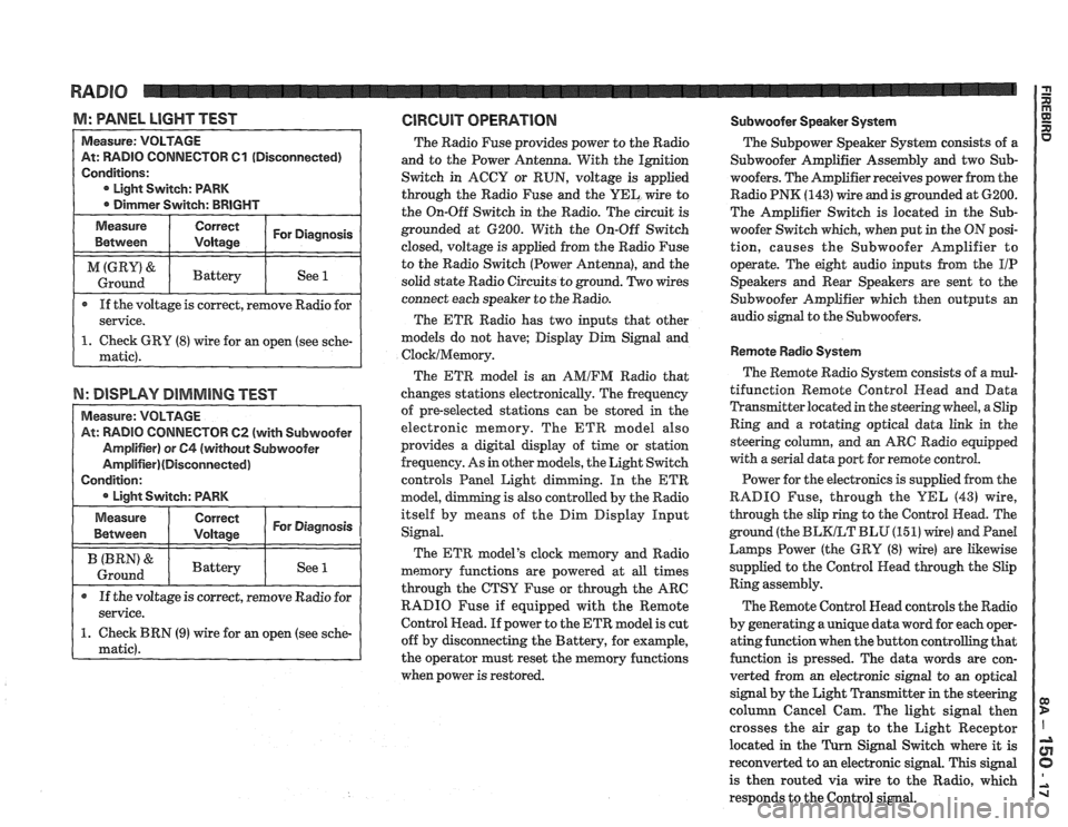
M: WNEL LIGHT TEST GlRGUlT OPERATION Subwoofer Speaker System
TOR 61 (Disconnected)
If the voltage is correct, remove Radio for
N: DISPLAY DIMMING TEST
TOW 62 (with Subwoofer
The Radio Fuse provides power to the Radio
and to the Power Antenna. With the Ignition
Switch in ACCY or RUN, voltage is applied
through the Radio Fuse and the
UEL wire to
the On-Off Switch in the Radio. The circuit is
grounded at 6200. With the On-Off Switch
closed, voltage is applied from the Radio Fuse
to the Radio Switch (Power Antenna), and the
solid state Radio Circuits to ground. Two wires
connect each speaker to the Radio.
The ETR Radio has two inputs that other
models do not have; Display Dim Signal and
ClocklMemory.
The ETR model is an AMIFM Radio that
changes stations electronically. The frequency
of pre-selected stations can be stored
in the
electronic memory. The ETR model also
provides a digital display of time or station
frequency. As in other models, the Light Switch
controls Panel Light dimming. In the
ETR
model, g is also controlled by the Radio
itself by means of the Dim Display Input
Signal.
The ETR model's clock memory and Radio
memory functions are powered at all times
through the CTSY Fuse or through the ARC
RADIO Fuse if equipped with the Remote
Control Head. If power to the ETR model is cut
off by disconnecting the Battery, for example,
the operator must reset the memory functions
when power is restored. The
Subpower Speaker
System consists of a
Subwoofer Amplifier Assembly and two Sub-
woofers. The Amplifier receives power from the
Radio PNK
(143) wire and is grounded at 6200.
The Amplifier Switch is located in the
Sub-
woofer Switch which, when put in the ON posi-
tion, causes the Subwoofer Amplifier to
operate. The eight audio inputs from the
I/P
Speakers and Rear Speakers are sent to the
Subwoofer Amplifier which then outputs an
audio signal to the Subwoofers.
Remote Radio System
The Remote Radio System consists of a mul-
tifunction Remote Control
Head and Data
Transmitter located in the steering wheel, a Slip
Ring and a rotating optical data link in the
steering
colurnn, and an ARC Radio equipped
with a serial data port for remote control.
Power for the electronics is supplied from the
RADIO Fuse, through the
YEL (43) wire,
through the slip ring to the Control Head. The
ground (the
BLKLT BLU (15 1) wire) and Pand
Larnps Power (the GRY (8) wire) are Likewise
supplied to the Control Head through the Slip
Ring assembly.
The Remote Control Head controls the Radio
by generating a unique data word for each oper-
ating function when the button controlling that
function is pressed. The data words are con-
verted from an electronic signal to an optical
signal by the Light Transmitter in the steering
column Cancel Cam. The light signal then
crosses the air gap to the Light Receptor
located in the
Turn Signal Switch where it is
reconverted to
an electronic signal. This signal
is then routed via wire to the Radio, which
responds to the Control signal.
Page 1601 of 1825
88-2 LIGHTING SYSTEMS AND HORNS
The fog lights must be aimed for proper
illumination of the road. Fog light
aim should be
checked: at least once a year; when a new light housing
is installed; or if service or repairs in the front end area
have (or may have) disturbed the fog light mountings.
FRONT PARKING/TURM SIGNAL
LIGHTS - Pushing either side of the instrument panel
switch will turn on the front parking lights. (Pushing
the left side of the switch will also turn on the
headlights.) When the ignition is on and the turn signal
lever is moved, the appropriate front parking light
flashes to signal a turn. Both lights will flash when the
hazard flashers are on.
If the driver's door is opened when the parking
lights are on, a warning tone will sound. For more
information, see Section
8A-77.
HAZARD FLASHERS - The hazard warning
flasher is part of the turn signal circuit. Pushing in the
button (on the right side of the steering column) will
cause the front and rear turn signal lights, and the front
sidemarker lights, to flash. Pull out the collar around
the button to turn off the hazard flashers.
The hazard flashers will work with the ignition
either off or on. When the hazard flashers are on, the
turn signals do not
work.
The hazard flashers will stop flashing and stay on
brightly if the brake pedal is pushed down.
HEADLIGHTS - The headlights are controlled
by the switch on the instrument panel (to the left of the
speedometer). They will come on whether or not the
ignition is turned on. Pushing the upper left side of the
switch turns on the headlights and causes the headlight
motors to raise the headlights. Pushing the bottom part
of the switch turns off the headlights, and they should
lower.
If the driver's door is opened when the ignition
is off and the headlights are on, a warning tone will
sound. For more information, see Section
8A-77.
Headlight low-beam and high-beam are
controlled by the turn
signal/multifunction lever on
the left side of the steering column. When the
headlights are on, pull the lever toward the steering
wheel until the switch clicks; the lights will change
from low-beam to high-beam, or from high-beam to
low-beam. An indicator light on the center instrument
cluster will come on when the high-beam headlights
are on.
The headlights must be aimed for proper
illumination of the road. Headlight aim should be
checked: at least once a year; when a new headlight
bulb is installed; or if service or repairs in the front end
area have (or may have) disturbed the headlights or
their mountings. The headlight bezels do not need to
be removed to aim the headlights.
Headlight focus is set when the sealed-beam unit
is made; no adjustment for focus is necessary or
possible.
Some state and local laws specify
requirements for headlight aim; these laws
must be followed.
LICENSE PLATE LBGHTS -A light above the
rear license plate will come on when the headlights or
parking lights are on.
LIGHT SWITCH - Most exterior lights are
controlled by the switch on the instrument panel, to the
left of the speedometer. Pushing the upper right part
of the switch turns on the front parking lights, the
taillights and the sidemarker lights. (It also turns on
the instrument panel lights.) Pushing the upper left
part of the switch turns on all these lights plus the
headlights. Pushing the bottom part of the switch turns
off all lights.
In some cases (such as going through a car wash),
it may be desirable to raise the headlights without
leaving the headlights on. To do so, push the upper
right part of the switch to turn on the parking lights.
Then, lightly push the upper right part of the switch;
the headlights will raise but will not turn on.
(Remember that the parking lights and taillights will
stay on.)
For more information on this switch (including
on-car service), see Section
8C. Also see Section 8C for
information on interior lights.
REAR TAlL/STOP/TURN SIGNAL
LIGHTS - The rear tail/stop/turn signal lights are
part of the same light assembly. Pushing either side of
the instrument panel switch turns on the taillights.
When the brake pedal is pushed down, the lights glow
brighter to serve as stoplights.
Moving the turn signal lever when the ignition is
on causes the appropriate rear lights to flash. (If the
brake pedal is held down and a turn is signalled, one
side will flash and the other will stay on brightly.)
All lights will flash when the hazard flashers are
on. However, if the brake pedal is pushed while the
hazard flashers are on, the lights will stop flashing and
stay on brightly.
SIDEMARKER LIGHTS -The front and rear
sidemarker lights will come on when the headlights or
parking lights are on. Both front and rear sidemarker
lights also have reflectors; they will shine when struck
by light, whether or not the car's lights are on.
If the headlights or parking lights are off when a
turn is signalled, the front sidemarker light will flash
in unison with the front turn signal light on the same
side. If the lights are on when a turn is signalled, the
front
sidemarker light and front turn signal light flash
alternately.
TURN SlG N ALS - The front turn signals are
combined with the front parking lights. The rear turn
signals are part of the rear
tail/stop/turn signal lights.
The turn signals work only when the ignition is on, and
the hazard flashers are turned off.
The turn signals are controlled by the turn
signal/multifunction lever on the left side of the
steering column. Moving the lever all the way up or
down (past the detent) will turn on the turn signals.
When the turn is completed, the lever will return to
neutral and the turn signals will stop flashing.
For changing lanes or shallow turns where the
steering wheel does not move far enough to cancel the
signal, move the turn signal lever only to the first
detent. When the lever is released, it will return to
neutral and the turn signals will cancel.
UNDERHOOD LIGHT - The underhood light
will come on when the hood is raised.