1988 PONTIAC FIERO distributor
[x] Cancel search: distributorPage 1426 of 1825
INSTRUMENT PANEL: DIGITAL CLUSTER
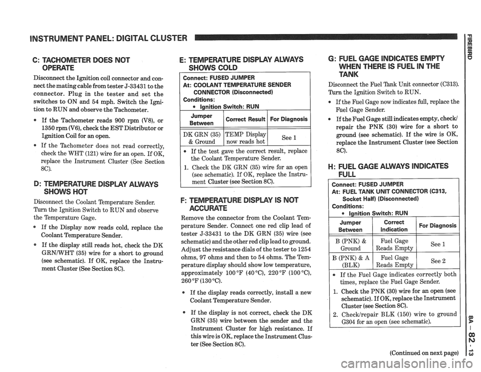
6: TAGHOMETER DOES NOT
OPEWTE
Disconnect the Ignition coil connector and con-
nect the matingcable from tester 5-33431 to the
connector. Plug in the tester and set the
switches to ON and 54 mph. Switch the Igni-
tion to RUN and observe the Tachometer.
If the Tachometer reads 900 rpm
(V8), or
1350
rpm (V6), check the EST Distributor or
Ignition Coil for an open.
If the Tachometer does not read correctly,
check the WHT (121) wire for an open. If OK,
replace the Instrument Cluster (See Section
8C).
D: TEMPEFIATURE DISPWY ALWAYS
SHOW nm
Disconnect the Coolant Temperature Sender.
Tum the Ignition Switch to RUN and observe
the Temperature Gage.
If the Display now reads cold, replace the
Coolant Temperature Sender.
* If the display still reads hot, check the DK
GRNIWHT (35) wire for a short to ground
(see schematic). If
OK, replace the Instru-
ment Cluster (See Section
86).
E: TEMPEFIATURE DISPLPIY ALMS
SHOWS GOLD
At: COOLANT TEMPERATURE SENDER
CONNECTOR (Disconnected)
Conditions:
Jumper
Between
F: TEMPEWTURE DISPWY IS NCIT
AGCUME
Remove the connector from the Coolant Tem-
perature Sender. Connect one red clip lead of
tester 5-33431 to the DK GRN (35) wire (see
schematic) and the other red clip lead to ground.
Adjust the resistance dials of the tester to 1254
ohms,
97 ohms and then to 54 ohms. The Tem-
perature display should show low temperature,
approximately 100
OF (40 "C), 220 OF (100 "C),
260 OF (130 "6).
r If the display reads correctly, install a new
Coolant Temperature Sender.
If the display is not correct, check the DK
GRN (35) wire between the sender and the
Instrument Cluster for high resistance. If
this wire is OK, replace the Instrument Clus-
ter (See Section
8C).
DK GRN (35)
& Ground
6: FUEL GAGE INDICATES EMPW
WHEN THERE IS FUEL IN THE
TANK
Correct Result
Disconnect the F'uel Tank Unit connector (C313).
Turn the Ignition Switch to RUN.
For Diagnosis
If the test gave the correct result, replace
the Coolant Temperature Sender.
1. Check the DK GRN (35) wire for an open
(see schematic). If OK, replace the Instru-
ment Cluster (see Section
8C).
TEMP Display
now reads hot
@ If the Fuel Gage now indicates full, replace the
F'uel Gage Sender.
See
a If the Fuel Gage still indicates empty, check/
repair the PNK (30) wire for a short to
ground (see schematic). If the wire is OK,
replace the Instrument Cluster (see Section
8C).
El: FUEL GAGE ALWAYS lNDl6ATES
FULL
Connect: FUSED JUMPER
At: FUEL TANK
UNIT CONNECTOR (C313,
Socket Half) (Disconnected)
Conditions: ignition Switch: RUN
I B (PNK) & I Fuel Gage I See (
Ground Reads Empty
Jumper
Between
If the Fuel Gage indicates correctly both
times, replace the Fuel Gage Sender.
1. Check the PNK (30) wire for an open (see
schematic).
If OK, replace the Instrument
Cluster (see Section
8C).
2. ChecMrepair BLK (150) wire to ground
6304 for an open (see schematic).
Correct
indication
B (PNK) & A
(BLK)
(Continued on next page)
For Diagnosis
Fuel Gage
Reads Empty See
2
Page 1553 of 1825
RADIO I
(Continued from previous page) from back of Radio
If noise persists with replacement antenna, the
problem must be repaired at the source of noise
(generator, ignition system, accessory, etc.). See
Delco Manual for noise "Sniffing" procedures.
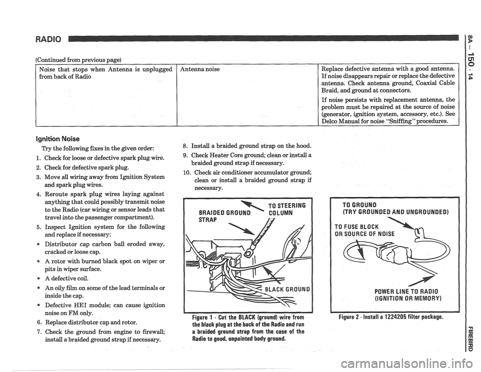
Ignition Noise
Trv the following. fixes in the piven order: 8. Install a braided ground strap on the hood. Replace
defective antenna with a good antenna.
If noise disappears repair or replace the defective
antenna. Check antenna ground, Coaxial Cable
Braid, and ground at connectors.
unplugged
- -
1. Check
for loose or defective spark plug wire.
2. Check for defective spark plug.
3. Move all wiring away from Ignition System
and spark plug wires. Antenna
noise
4. Reroute spark plug wires laying against
anything that could possibly transmit noise
to the Radio (car
g or sensor leads that
travel into the passenger compartment).
5. Inspect Ignition system for the following
and replace if necessary:
r Distributor cap carbon ball eroded away,
cracked or loose cap.
A rotor with burned black spot on wiper or
pits in wiper surface.
r A defective coil.
r An oily film on some of the lead terminals or
inside the cap.
Defective
WE1 module; can cause ignition
noise on
FM only.
6. Replace distributor cap and rotor.
9. Check Heater Core ground; clean or install a
braided ground strap if necessary.
10. Check air conditioner accumulator ground;
clean or install a braided ground strap if
necessarv.
TO STEERING
BRAIDED
GROUN GO LUMN
Figure 1 - Gut the BLACK (ground) wire from
the black plug
at the back of the Radio and run
7. Check the ground from engine to firewall, a braided ground strap from the ease of the
install a braided ground strap if necessary. Radio to good, unpainted body ground.
(TRY GROUNDED AND UNGROUNDED)
POWER LlNE TO RADIO
(IGNITION OR MEMORY)
Figure 2 - install a 1224205 filter package.
Page 1564 of 1825
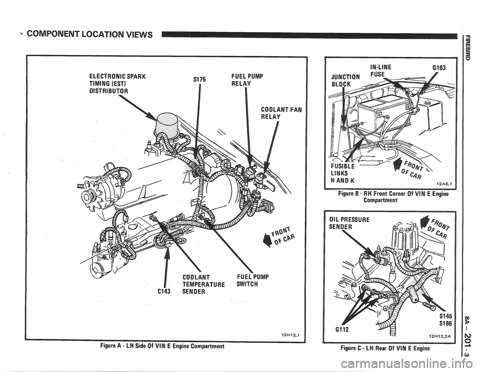
COMPONENT LOCATION VIEWS
ELECTRONIC SPARK
S175 FUEL
PUMP
TIMING (EST) RELAY
DISTRIBUTOR
I TEMPERATURE SWITCH
6143 SENDER Figure
B - RH
Front Corner Of VIM E Engine
Compartment
/ OIL PRESSURE
Figure C
- LH Rear Of VIN E Engine
Page 1567 of 1825
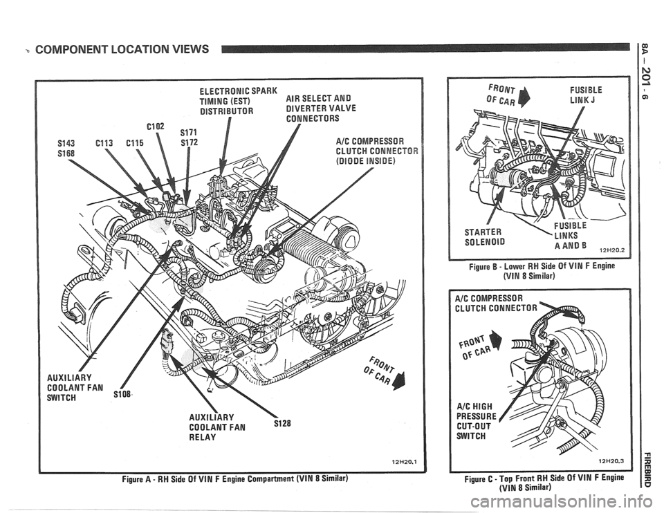
3 COMPONENT LOCATIQN VIEWS ca D
l
ELECTRONIC SPARK
TIMING (EST) AIR
SELECT AND
DISTRIBUTOR DlVERTER VALVE
A/C COMPRESSOR
CLUTCH
CONNECTOR
AUXlLlARY
COOLANT FAN
RE LAY
Figure
A - RM Side Of VIN F Engine Compartment (VIN 8 Similar) Figure
B - Lower
RW Side Of VIN F Engine
(VlN 8 Similar)
A/C COMPRESSOR -
CLUTCH CONNECTOR
I
Figure C - Top Front RM Side Of VIN F Engine
(VIN 8 Similar)
Page 1675 of 1825
9G-2 MISCELLANEOUS ACCESSORIES
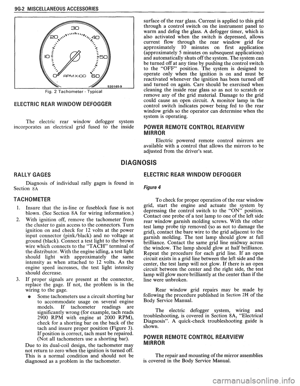
Fig. 2 Tachometer - Typical
RPMX I00 €31-
ELECTRIC REAR WINDOW DEFOGGER
surface of the rear glass. Current is applied to this grid
through a control switch on the instrument panel to
warm and defog the glass. A defogger timer, which is
also activated when the switch is depressed, allows
current flow through the rear window grid
for
approximately 10 minutes on first application
(approximately
5 minutes on subsequent applications)
and automatically shuts off the system. The system can
be turned off at any time by pushing the control switch
to the "OFF" position. The system is designed to
operate only when the ignition is on and must be
reactivated whenever the ignition has been turned off
and turned on again. Care should be exercised when
cleaning the inside rear glass so as not to scratch or
remove any of the grid material. Damage to the grid
could cause an open circuit. A monitor lamp in-the
control switch indicates power being fed to the rear
window grids so the operator can determine when the
system is operating.
The electric rear window defogger system
incorporates an electrical grid fused to the inside
POWER REMOTE CONTROL REARVIEW
MIRROR
Electric powered remote control mirrors are
available with a control that allows the mirrors to be
adjusted from the driver's seat.
RALLY GAGES ELECTRIC REAR WINDOW DEFOGGER
Diagnosis of individual rally gages is found in
Section
8A Figure 4
TACHOMETER To check for moper o~eration of the rear window
1. Insure that the in-line or fuseblock fuse is not
blown. (See Section 8A for wiring information.)
2. With ignition off, remove the tachometer from
the cluster to gain access to the connectors. Turn
ignition on and check for
12 volts at the power
input connector
(pink/black) and no voltage at
ground (black). Connect a test light to the brown
wire which connects to the "TACH" terminal of
the distributor. With the engine idling, a test light
should light with approximately the same
intensity as when attached to
12 volts. As the
engine speed increases, the test light intensity
should decrease.
3. If proper signals are present at the connector,
replace the gage. If not, the problem is in the
wiring to the gage.
Some tachometers use a circuit shorting bar
to accommodate usage on several engine
models. If tachometer readings are
significantly wrong (for example, tach reads
2900 RPM with engine at 2000 RPM),
check for a shorting bar on the back of the
tach and insure proper position (Figure
3).
If position is correct, tach must be repaired.
(Not all tachometers use a shorting bar).
Due to its dual-coil design, the tachometer
may
- grid, start the engine a& actuate the system by
depressing the control switch to the
"ON" position.
Contact one probe of a test lamp to one of the left side
rear window garnish molding screws. With the other
test lamp probe tip removed (so as not to damage the
grid), contact the bare wire to the grid adjacent to the
garnish molding. The test lamp should glow at full
brilliance. Contact the same grid line midway across
the window. The lamp should glow at half brilliance.
Repeat the procedure for each grid line. If an open
circuit exists in a grid line between the left side and the
center, the test lamp will not glow. If there is an open
circuit between the center and the right side, the test
lamp will glow more brilliantly at the center than if the
line were unbroken.
Rear window grid repairs may be made by
following the procedure published in
Section 2H of the
Body Service Manual.
The electric defogger system, wiring and
troubleshooting, is covered in Section
8A, "Electrical
Diagnosis". A quick-check troubleshooting guide is
shown.
POWER REMOTE CONTROL REARVIEW
MIRROR
not return to zero when tvhe ignition is turned off'.
This is a normal condition and should not be The
repair and mounting of the mirror assemblies
diagnosed as a problem in the tachometer. is
covered in the Body Service Manual.