1988 PONTIAC FIERO distributor
[x] Cancel search: distributorPage 723 of 1825
6E3-Cl-4 2.8L (VIN S) DRIVEABILITY AND EMISSIONS
BarWNeutral Switch (Auto Only)
The ParWNeutral (PIN) switch indicates to the
ECM when the transmission is in Park or Neutral.
This information is used for the TCC and the IAC
valve operation.
Important
Vehicle should not be driven with ParWNeutral
switch disconnected as idle quality will be affected
and a possible false Code
24 (VSS).
See Section "$A" for more information on the PIN
switch, which is part of the neutrallstart and backup
light switch assembly.
NC '"n" Signal
This signal tells the ECM that the A/C selector
Switch is turned on, and that the pressure cycling
switch is closed. The ECM uses this to adjust the idle
Speed when the air conditioning is working.
If this signal is not available to the ECM, idle may
be rough, especially when the
A/C compressor cycles.
The voltage at ECM terminal "B8" should equal
battery voltage when
AIC is requested and the
pressure cycling switch is closed.
The signal at
B8 will cause the ECM to turn on the
A/C clutch by energizing the A/C relay.
Distributor Reference Signal
The distributor sends a signal to the ECM to tell it
both engine RPM and crankshaft position. See EST
System for further information.
To read the codes, use a "Scan" tool or ground the
diagnostic terminal with the engine not running and
the ignition on. The "Service Engine Soon" light will
flash Code 12 three times and
then flash each code
stored in memory three times. All codes stored in
memory would have been read when Code 12 was
flashed again. No new codes can be stored when in the
Diagnostics Mode (diagnostics lead grounded).
This
eliminates confusion while the system is being worked
on. To clear the codes from memory:
@ Ignition off
@ Remove fuse located in a weather proof holder
located near the battery for 30 seconds.
Since the ECM can have
a failure which may
effect only one circuit, following the Diagnostic
Procedures in this section will determine which circuit
has a problem and where it is. If
a diagnostic chart indicates that the ECM
connections or ECM is the cause of
a problem and the
ECM is replaced, but does not correct the problem, one
of the following may be the reason:
€9
connections. - The diagnostic chart will say "ECM
connections or ECM. The terminals may have to be
removed from the connector in order to check them
properly.
@ The ECM or PROM is not correct for the
application.
- The incorrect components may cause a
malfunction and may or may not set a code.
@ The problem is intermittent. - This means that
the problem is not present at the time the system is
being checked. In this case, refer to the "Symptoms"
portion of the manual and make a careful physical
inspection of all portions of the system involved.
@ Shorted solenoid, relay coil, or harness. -
Solenoids and relays are turned "ON" and "OFF" by
the
ECM,using internal electronic switches called
"Drivers". Each driver is part of
a group of four called
"Quad-drivers". Failure of one driver can damage any
other driver in the set.
Solelloid and relay coil
resistance must measure more than 20 ohms. Less
resistance will cause early failure of the ECM
"driver". A shorted solenoid, relay coil, or harness,
with a GMP4 computer, will not damage the ECM, but
will cause the component to be inoperative.
Before replacing an ECM, be sure to check the coil
resistance of all solenoids and relays controlled by the
ECM. See ECM wiring diagram for the
solenoid(s)
and relay(s) and the coil terminal identification.
534636 or BT 8405 testers or equivalent provide
a fast, accurate means of checking for a shorted coil or
a short to battery voltage.
@ The PROM may be faulty. - Although these
rarely fail, it operates as part of the ECM. Therefore,
it could be the cause of the problem. Substitute a
known good PROM.
@ The replacement ECM may be faulty. - After the
ECM is replaced, the system should be rechecked for
proper operation. If the diagnostic chart again
indicates the ECM is the problem, substitute
a known
good ECM. Although this is a rare condition, it could
happen.
ECM
A faulty ECM will be determined in the diagnostic
charts or
by a Code 55.
PROM
A faulty PROM may result in a Code 51.
Page 737 of 1825
Starting Mode
When the ignition is first turned "ON," the ECM
will turn "ON" the fuel pump relay for two seconds,
and the fuel pump will build up pressure. The ECM
then checks the coolant temperature sensor, throttle
position sensor, and determines the proper airlfuel
ratio for starting. This ranges from 1.5
: 1 at -36°C (-
33°F ) to 14.7 : 1 at 94°C ( 201°F ). The ECM controls
the amount of fuel delivered in the STARTING mode
by changing how long the injectors are pulsed "ON".
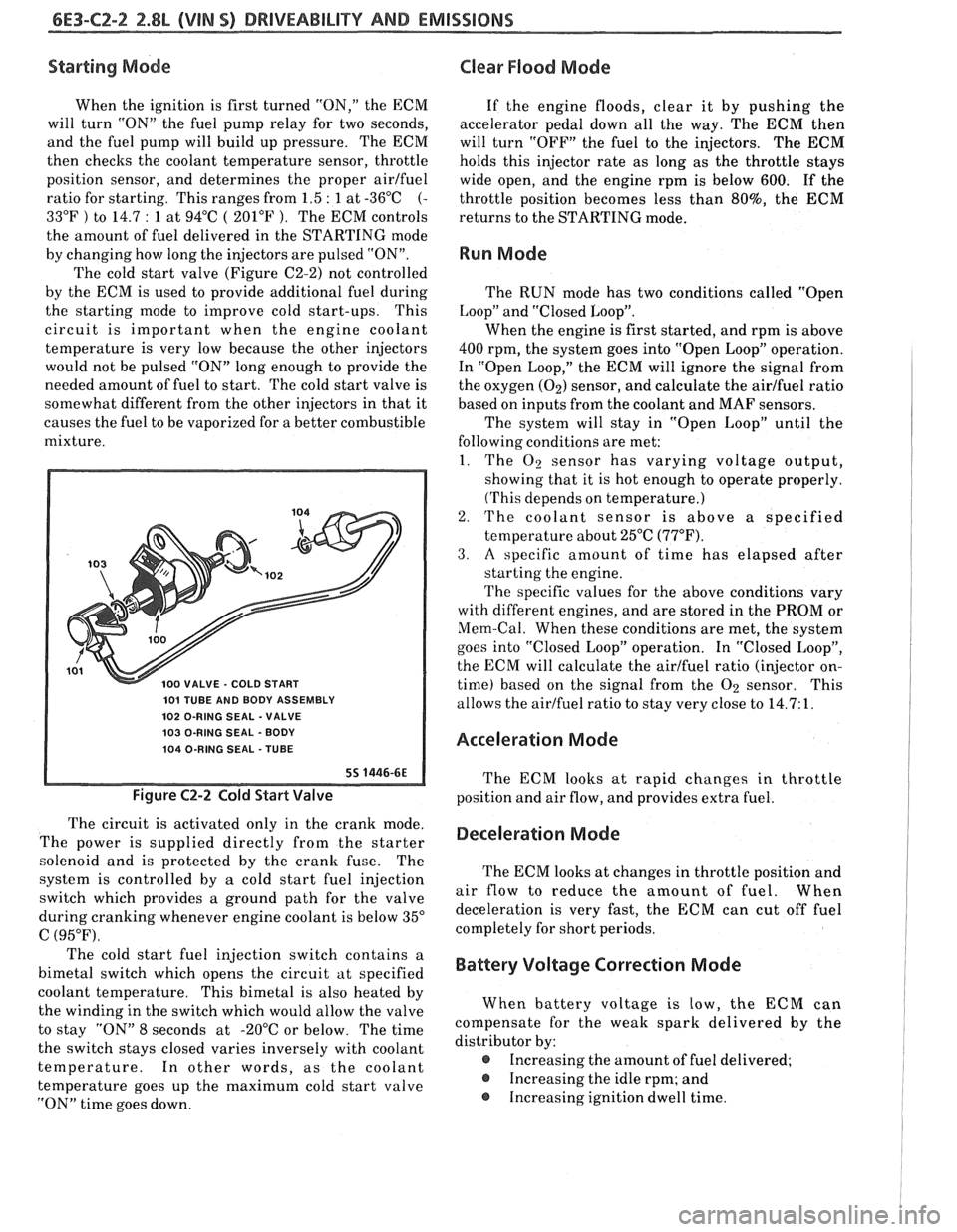
The cold start valve (Figure C2-2) not controlled
by the ECM is used to provide additional fuel during
the starting mode to improve cold start-ups. This
circuit is important when the engine coolant
temperature is very low because the other injectors
would not be pulsed "ON" long enough to provide the
needed amount of fuel to start. The cold start valve is
somewhat different from the other injectors in that it
causes the fuel to be vaporized for a better combustible
mixture.
101 TUBE AND BODY ASSEMBLY
102 O-RING SEAL
- VALVE
103 O-RING SEAL
- BODY
104 O-RING SEAL
- TUBE
Figure C2-2 Cold Start Valve
The circuit is activated only in the crank mode.
The power is supplied directly from the starter
solenoid and is protected by the crank fuse. The
system is controlled by
a cold start fuel injection
switch which provides
a ground path for the valve
during cranking whenever engine coolant is below 35"
C (95°F).
Clear Flood Mode
If the engine floods, clear it by pushing the
accelerator pedal down all the way. The
ECM then
will turn "OFF" the fuel to the injectors. The
ECM
holds this injector rate as long as the throttle stays
wide open, and the engine rpm is below
600. If the
throttle position becomes less than
80%, the ECM
returns to the STARTING mode.
Run Mode
The RUN mode has two conditions called "Open
Loop" and "Closed Loop".
When the engine is first started, and rpm is above
400 rpm, the system goes into "Open Loop" operation.
In "Open Loop," the ECM will ignore the signal from
the oxygen
(02) sensor, and calculate the airlfuel ratio
based on inputs
from the coolant and MAF sensors.
The system will stay in "Open Loop" until the
following conditions are met:
1. The
O2 sensor has varying voltage output,
showing that it is hot enough to operate properly.
(This depends on temperature.)
2. The coolant sensor is above a specified
temperature about 25°C
(77°F).
3. A specific amount of time has elapsed after
starting the engine.
The specific values for the above conditions vary
with different engines, and are stored in the PROM or
Mem-Cal. When these conditions are met, the system
goes into "Closed Loop" operation. In "Closed Loop",
the ECM will calculate the airlfuel ratio (injector on-
time) based on the signal from the
O2 sensor. This
allows the airlfuel ratio to stay very close to 14.7: 1.
Acceleration Mode
The ECM looks at rapid changes in throttle
position and air flow, and provides extra fuel.
Deceleration Mode
The ECM looks at changes in throttle position and
air flow to reduce the amount of fuel. When
deceleration is very fast, the ECM can cut off fuel
completely for short periods.
The cold start fuel injection switch contains a
bimetal switch which opens the circuit at specified
Battery Voltage Correction Mode
coolant temperature. This bimetal is also heated by
the winding in the switch which would allow the valve When battery
voltage is low, the ECM can
to stay "ON" 8 seconds at -20°C or below. The time compensate
for the weak spark delivered by the
the switch stays closed varies inversely with coolant distributor
by:
temperature. In other words, as the coolant
@ Increasing the amount of fuel delivered;
temperature goes up the maximum cold start valve
@ Increasing the idle rpm; and
"ON" time goes down. Increasing ignition
dwell time.
Page 738 of 1825
DRIVEABILITY AND EMISSIONS 2.8L (VIN 5) 6E3-CZ-3
Fuel Cutofl Mode
No fuel is delivered by the injector when the
ignition is "OFF". This prevents dieseling. Also, fuel
is not delivered if no reference pulses are seen from
the distributor, which means the engine is not
running. This prevents flooding.
Fares Control System Components
The fuel control system is made up of the following
parts:
e Fuel Injectors
@ Throttle Body
e Fuel pump relay
@ Fuel Pressure Regulator
@ Fuel Rail
Basic System Operation
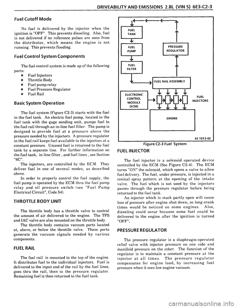
The fuel system (Figure C2-3) starts with the fuel
in the fuel tank. An electric fuel pump, located in the
fuel tank with the gage sending unit, pumps fuel to
the fuel rail through an in-line fuel filter. The pump is
designed to provide fuel at a pressure above the
pressure needed by the injectors. A pressure regulator
in the fuel rail keeps fuel available to the injectors at a
constant pressure. Unused fuel is returned to the fuel
tank by a separate line. For further information on
the fuel tank, in-line filter
, and fuel lines , see Section
"6C".
The injectors, are controlled by the ECM. They
deliver fuel in one of several modes, as described
above. In order to properly control the fuel supply, the
fuel pump is operated by the ECM thru the fuel pump
relay and oil pressure switch (see
"Fuel Pump
Electrical Circuit", Code 54).
THROTTLE BODY UNIT
The throttle body has a throttle valve to control
the amount of air delivered to the engine. The TPS
and
IAC valve are also mounted on the throttle body.
The throttle body contains vacuum ports located
at, above, or below the
throttIe valve. These ports
generate the vacuum signals needed by various
components.
FUEL RAIL
The fuel rail is mounted to the top of the engine.
It distributes fuel to the individual injectors. Fuel is
delivered to the input end of the rail by the fuel lines,
goes thru the rail, then to the pressure regulator.
Remaining fuel is then returned to the fuel tank.
Figure C2-3 Fuel System
FUEL INJECTOR
The fuel injector is a solenoid operated device
controlled by the ECM (See Figure C2-4). The ECM
turns
"ON" the solenoid, which opens a valve to allow
fuel delivery. The fuel, under pressure, is injected in a
conical spray pattern at the opening of the intake
valve. The fuel which is not used by the injectors
passes through the pressure regulator before being
returned to the fuel tank.
An injector which is stuck partly open will cause
loss of pressure after engine shut down, so long crank
times would be noticed on some engines. Also,
dieseling could occur because some fuel could be
delivered to the engine after the ignition is turned
"OFF".
PRESSURE REGULATOR
The pressure regulator is a diaphragm-operated
relief valve with injector pressure on one side and
manifold pressure on the other. The function of the
regulator is to maintain a constant pressure at the
injector at all times. The pressure regulator
compensates for engine load, by increasing fuel
pressure when it sees low engine vacuum.
Page 742 of 1825
DRIVEABILITY AND EMISSIONS 2.8L (VIN S) 6E3-CZ-7
100 VALVE - COLD START
101 TUBE AND BODY ASSEMBLY
102 O-RING SEAL -VALVE
103 O-RING SEAL - BODY
104 O-RING SEAL -TUBE
Figure C2-8 Cold Start Valve Assembly
important
At any time the fuel system is opened for service,
the O-ring seals used with related
component(s)
should be replaced.
a Cleaning and a Inspection
Before disassembly, the fuel rail assembly may be
cleaned with a spray type engine cleaner, such as AC
Delco X-30A or equivalent, following package
instructions. The fuel rail should not be immersed in
liquid solvent.
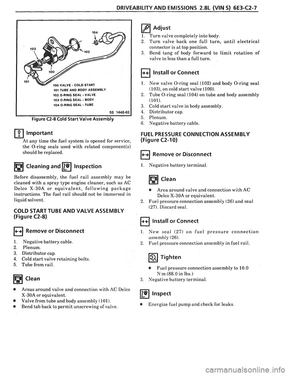
COLD START TUBE AND VALVE ASSEMBLY
(Figure C2-8)
Remove or Disconnect
1. Negative battery cable.
2. Plenum.
3. Distributor cap.
4. Cold start valve retaining bolts.
5. Tube from rail.
Clean
@ Areas around valve and connection with AC Delco
X-30A or equivalent.
@ Valve from tube and body assembly (101).
@ Bend tab back to permit unscrewing of valve.
@ Adjust
1. Turn valve completely into body.
2. Turn valve back one full turn, until electrical
connector is at top position.
3. Bend tang of body forward to limit rotation of
valve to less than
a full turn.
Install or Connect
1. New valve O-ring seal (102) and body O-ring seal
(103), on cold start valve (100).
2. Tube O-ring seal (104) on tube and body assembly
(101).
3. Cold start valve in body assembly.
4. Distributor cap.
5. Plenum.
6. Negative battery cable.
FUEL PRESSURE CONNECTION ASSEMBLY
(Figure
C2-I 0)
Remove or Disconnect
1. Negative battery terminal.
Clean
@ Area around valve and connection with AC
Delco X-30A or equivalent.
2. Fuel pressure connection assembly (26) and seal
(27). Discard seal.
Install or Connect
1. New seal (27) on fuel pressure connection
assembly
(26).
2. Fuel pressure connection assembly in fuel rail.
Tighten
@ Fuel pressure connection assembly to 10.0
N.m (88.0 in lbs.)
3. Negative battery terminal.
a inspect
@ Energize fuel pump and check for leaks.
Page 764 of 1825
DRIVEABILITY AND EMISSIONS 2.8L (VIN S) 6E3-C4-1
SECTION C4
IGNI"F0N SYSTEM / EST
CONTENTS
GENERAL DESCRIPTION ................ C4-1 ON-CAR SERVICE ..................... C4-2
PURPOSE ......................... C4-1 SETTING TIMING.. .................. C4-2
OPERATION ....................... C4-1 HOW CODE 42 IS DETERMINED.. ....... C4-2
RESULTS OF INCORRECT OPERATION .... C4-2 PARTS INFORMATION ................. C4-2
DIAGNOSIS
......................... C4-2
CODEIZ.......................... C4-2
GENERAL DESCRIPTION
PURPOSE
The High Energy Ignition ([-IEI) system controls
fuel combustion by providing a spark to ignite the
compressed
airlfuel mixture at the correct time. To
provide improved engine performance, fuel economy,
and control of exhaust emissions, the
ECM controls
distributor spark advance (timing) with the Electronic
Spark Timing (EST) system.
Only the Electronic Spark Timing (EST) system
will be described here. Additional information on the
tIEI system is found in Section "6D".
To properly control ignition/combustion timing
the ECM needs to know:
@ Crankshaft position
@ Engine speed (rpm)
@ Mass Air Flow
@ Engine temperature
OPERATION
The EST system consists of the distributor
module, ECM, and connecting wires. The connector
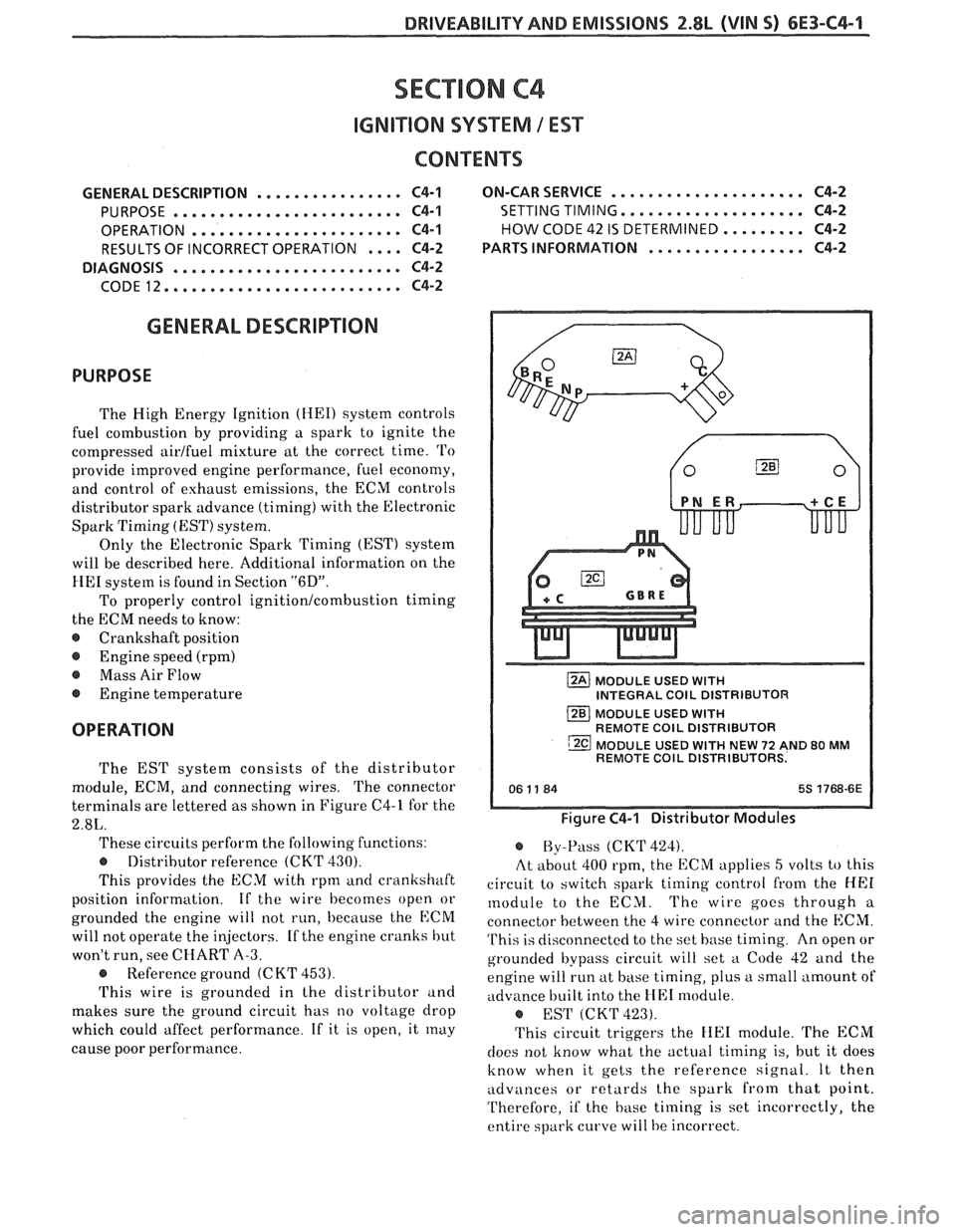
terminals are lettered as shown in Figure C4-1 for the
2.8L.
These circuits perform the following functions:
@ Distributor reference (CKT 430).
This provides the ECM with rpm ancl crankshaft
position information. If
the wire becomes open or
grounded the engine will not run, because the
ECM
will not operate the injectors. If the engine cranks hut
won't run, see CHART A-3.
@ Reference ground (C KT 453).
This wire is grounded in the distributor and
makes sure the ground circuit has no voltage drop
which could affect performance. If it is open, it
rnay
cause poor performance.
MODULE USED WITH INTEGRAL COlL DISTRIBUTOR
MODULE USED
WITH REMOTE COlL DISTRIBUTOR
MODULE USED
WITH NEW 72 AND 80 MM REMOTE COlL DISTRIBUTORS.
Figure C4-1 Distributor Modules
@ By-Pass (CKT 424).
At about 400 rpm, the ECM applies
5 volts to this
circuit to switch spark timing control from the
HE1
module to the ECM. The wire gocs through a
connector between the
4 wire connector and the ECM.
This is disconnectcd to the set base timing. An open or
grounded bypass circuit will set
a Code 42 and the
engine will run at hase timing, plus a small amount of
advance built into the
HE1 n~odule.
@ EST (CKT423).
This circuit triggers the FIE1 module. The ECM
does not know what the actual timing is, but it does
know when it gets the reference signal. It then
udva~ces or retards the spark from that point.
Therefore, if the
hase timing is set incorrectly, the
entire spark curve will be incorrect.
Page 765 of 1825
6E3-C4-2 2.8L (WIN S) DRIVEABILITY AND EMISSIONS
RESULTS OF INCORRECT OPERATION
An open or ground in the EST circuit will set a
Code 42 and cause the engine to run on the HE1
module timing. This will cause reduced performance
and poor fuel economy.
The ECM uses information from the
MAF and
coolant sensors in addition to rpm to calculate spark
~tdvance as follows:
@ Cold engine = more spark advance.
@ Engine under minimum load based on rpm
and low amount of air flow- more spark
advance. Hot engine
= less spark advance.
@ Engine under heavy load based on rprn and
high amount of air flow- less spark advance.
The description, operation, and diagnosis of the
HE1 system are found in Section "GD" of this manual.
CODE 12
Code 12 is used during the Diagnostic Circuit
Check procedure to test the code display ability of the
ECM. This code indicates that the ECM is not
receiving the engine
rpnl (REFERENCE) signal. This
occurs with the ignition key "ON" and the engine not
running.
The "Reference" signal also triggers the fuel
injection system. Without the "Reference" signal the
engine cannot run.
OM-CAR SERVICE
SETTING TIMING
The initial base timing is set by disconnecting the
timing connector, located near the blower motor.
Refer to Emission Control Information Label for
procedure.
This will cause Code 42 to store in the code
memory of the ECM.
The memory must be cleared
after setting timing.
How Code 42 Is Determined
When the system is running on the HE1 module,
that is no voltage on the bypass line, the
HE1 module
grounds the EST signal.
The ECk1 expects to see no
voltage
on the EST line during this condition. If it sees
a voltage, it sets code 42 and will not go into the EST
mode.
When the rpm for EST
is reachecl bout 300 rprn)
the ECM applies 5 volts to the bypass line and the E:SrI'
should no longer be grounded in the tIEI nodule so
the EST voltage should be varying.
If the bypass line is open or grounclecl, the IIEI
tnod~lle will not switch to EST mode so the EST
voltage will be low
and Code 42 will be set. Refer to
Section
"611" for on vehicle service.
PARTS INFORMATION
PART NAME GROUP
Controller, ECM
(Remanufi~ctured) ................ 3.670
.......................... Distributor 2.36 1
Module, Distr ........................ 3.380
........................... Coil, Distr 2.170
Page 767 of 1825
6E3-C4-4 2.8L (VIN S) DRIVEABILITY AND EMISSIONS
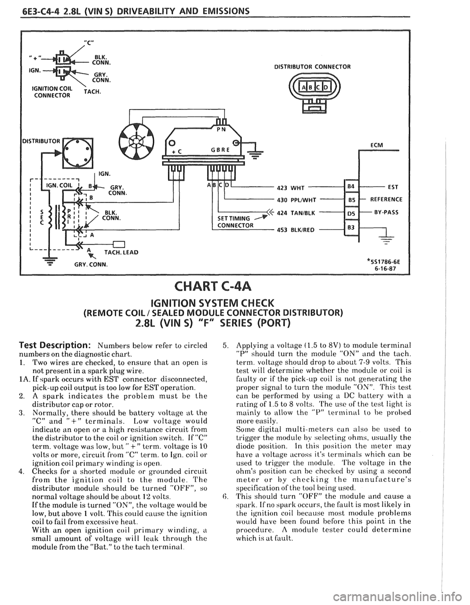
430 PPLMlHT - 85 - REFERENCE
424
TANIBLK
453 BLWRED
CHART C-4A
IGNITION SYSTEM CHECK
(REMOTE COIL / SEALED MODULE CONNECTOR DISTRIBUTOR)
2.8L (VIN 5) "F" SERIES (PORT)
Test Description: Numbers below refer to circled
numbers on the diagnostic chart.
1. Two wires are checked, to ensure that an open is
not present in
a spark plug wire.
1A. If spark occurs with EST connector disconnected,
pick-up coil output is too low for
EST operation.
2. A spark indicates the problem must be the
distributor cap or rotor.
3. Normally, there should he battery voltage at the
"C" and "+" terminals. Low voltage would
indicktte an open or a high resistance circuit from
the distributor to the coil or ignition switch. If
"C"
term. voltage was low, but " +" term. voltage is 10
volts or more, circuit from "C" term. to Ign. coil or
ignition coil primary winding is open.
4. Checks for a shorted module or grounded circuit
from the ignition coil to the module. The
distributor
nodule should be turned "OFF", so
normal voltage should be about
1% volts.
If the module is turned "ON", the voltage would be
low, but above
1 volt. 'I'his could cause the ig~lition
coil to fail from excessive heat.
With an open ignition coil primary
winding, i~
small amount of voltage will leak through the
module from the "Rat." to the tach terminal.
5. Applying a voltage (1.5 to 8V) to module terminal
"P" should turn the nlodule "ON" and the tach.
term. voltage should drop to about
7-9 volts. This
test will determine whether the module or coil is
faulty or if the pick-up coil is not generating the
proper signal to turn the
rnodule "ON". 'Phis test
can be performed by using a I)C battery with a
rating of
1.5 to 8 volts. The i~sc of the test light is
mainly to allow the
"P" terminal to be probed
more easily.
Some digital multi-meters can also be used t,o
trigger the module by selecting ohms, i~sually the
diode position. In this position the meter
may
have a voltage across it's terminals which can be
used to trigger the module.
'I'he voltage in the
ohm's position can be checked by
using a second
meter or by checking the manufacture's
specification of the tool being used.
6. This should turn "OFF" the nlodule and cause a
spark. If no
spark occurs, the fault is most likely in
the ignition coil because most module problems
would have been found before this point in the
procedure.
A moclule tester could determine
which is at fault.
Page 806 of 1825
DRIVEABILITY AND EMISSIONS 5.OL (VIN F) & 5.7L (VIN 8) 6E3-A-3
- ORN 461
T
TO MAF AND FUEL
PUMP RELAY AND
FAN CONTROL
SWITCH
ALDL CONN
I ENGINE
ENGINE GROUND
GROUND
-
OXYGEN SENSOR
TAN 413
MANIFOLD AIR TAN 472
TEMPERATURE SENSOR
GRY
416
K BLU 417
BLK 452
COOLANT
TEMPERATURE
SENSOR
YEL4lO
PICK-UP COlL
PRIMARY COlL I ..
- WHT
PPWHT
TANJBLK
BLWRED SERIAL
DATA
DIAGNOSTIC TEST
SYSTEM GROUND
SYSTEM GROUND
BACK
SYSTEM GROUND OF
CONNECTOR
OXYGEN SENSOR
SIGNAL
OXYGEN SENSOR
GROUND
24 PIN
A-0 CONNECTOR
MAT SENSOR
SIGNAL
BACK
VIEW OF
CONNECTOR
+ 5V REF.
TPS SIGNAL
5V RETURN
COOLANT TEMP.
SIGNAL
32 PIN C-D
CONNECTOR
EST
REFERENCE
BY-PASS
DISTRIBUTOR GROUND
8s 4240
7-13-87