1988 PONTIAC FIERO distributor
[x] Cancel search: distributorPage 561 of 1825
6EZ-C1-6 5.OL (VIN E) DRIVEABILITY AND EMISSIONS
A failure in the MAT sensor circuit should set a Code
23 or 25. The code charts also contain
a chart to check
for sensor resistance values relative to temperature.
MAP Sensor
A "ScanJ' tool reads manifold pressure and will
display either volts or
kPa of pressure.
Key "ONJ', engine stopped, (no vacuum), MAP will
read high voltage or pressure, while at idle
(highvacuum), MAP will read low voltage or pressure.
Likewise, on accel., MAP will read high and on decel.,
will read low.
A failure in the MAP sensor, or circuit, should
result in a Code 33 or 34.
Oxygen (02) Sensor
The "Scan" tool has several positions that will
indicate the state of the exhaust gases,
02 voltage,
integrator, and block learn. See "Scan" tool position
information in the Introduction of Section
"6E".
A problem in the O2 sensor circuit should set a
Code 13 (open circuit), Code
44 (lean 02 indication),
Code
45 (rich 02 indication). Refer to the applicable
chart, if any of these codes were stored in memory.
Throttle Position Sensor (TPS)
A "Scan" tool displays throttle position in volts.
The
5.OL should read under 1.25 volts, with throttle
closed and ignition on, or at idle. Voltage should
increase at a steady rate as throttle is moved toward
WOT. The ECM has the ability to Auto-Zero the TPS
voltage, if it is below about 1.25 volts. This means
that any voltage less than 1.25 volts volts will be
determined by the ECM to be
0% throttle. Some
"Scan" tools have the ability to read the percentage of
throttle angle and should read
0%, when the throttle
is closed.
A failure in the TPS circuit or TPS, should
set a Code 21 or 22.
Vehicle Speed Sensor (VSS)
A "Scan" tool reading should closely match with
speedometer reading, with drive wheels turning. A
failure in the VSS circuit should set a Code
24.
PIN Switch
A "Scan" tool should read "ON", when in park or
neutral and "OFF", when in drive. This reading may
vary with different makes of tools. Refer to CHART C-
IA for
PIN switch diagnosis.
Power steering Pressure Switch (POPS)
A Scan" tool should read "OFF" normally, and
"ON" with high pressure. This reading may vary with
different makes of tools. Refer to CHART
C-1E for
PSPS diagnosis.
NC Request Signal
If the low pressure switch is closed and AIC is
"ON", the "Scan" tool should indicate
A/C "ON".
Distributor Reference Signal
A "Scan" tool will read this signal and is displayed
in rpm. See Section
"C4", for more information on the
Ignition System
.
Knock Signal
A "Scan" tool will indicate when the ESC module
signals the ECM that knock is present. See Section
"C5" for further information on the ESC System.
ON-CAR SERVICE
ELECTRONIC CONTROL MODULE (ECM)
Service of the ECM should normally consist of
either replacement of the ECM or a PROM change.
If the diagnostic procedures call for the ECM to be
replaced, the engine calibrator (PROM) and ECM
should be checked first to see if they are the correct
parts. If they are, remove the PROM from the faulty
ECM and install it in the new service ECM. THE
SERVICE ECM
WILL NOT CONTAIN A PROM.
Trouble Code "51" indicates the PROM is installed
improperly or has malfunctioned. When Code "51" is
obtained, check the PROM installation for bent pins or
pins not fully seated in the socket. If the PROM is
installed correctly and Code
"51" still shows, replace
the PROM.
Important
When replacing the production ECM with a
service ECM (controller), it is important to
transfer the Broadcast code and production ECM
number to the service ECM label. Please do not
record on ECM cover. This will allow positive
identification of ECM parts throughout the service
life of the vehicle.
Page 577 of 1825
6EZ-C2-2 DRIVEABILITY AND EMISSIONS - 5.8b (VIN E)
1.5:1 at -36°C (-33°F) to 14.7:1, at 94°C (201°F)
running temperature.
The ECM controls the amount of fuel delivered in
the starting mode by changing how long the injector is
turned "ON" and "OFF". This
is done by "pulsing" the
injector for very short times.
Clear Flood Mode
If the engine floods, clear it by pushing the
accelerator pedal down all the way. The ECM then
pulses the injector at a
20:1 airlfuel ratio, and holds
this injector rate as long as the throttle stays wide
open, and the engine is below 600 rpm. If the throttle
position becomes less than
80%, the ECM returns to
the starting mode.
Run Mode
The run mode has two conditions called "Open
Loop" and "Closed Loop."
Open Loop
When the engine is first started, and it is above
400 rpm, the system goes into "Open Loop" operation.
In "Open Loop," the ECM ignores the signal from the
(02) sensor, and calculates the airlfuel ratio based on
inputs from the coolant temperature and MAP
sensors.
The system stays in "Open Loop" until the
following conditions are met:
1. The
O2 sensor has varying voltage output,
showing that it is hot enough to operate properly.
(This depends on temperature.)
2. The coolant temperature sensor is above a
specified temperature.
3. A specific amount of time has elapsed after
starting the engine.
Closed Loop
The specific values for the above conditions vary
with different engines, and are stored in the
programmable read only memory (PROM). When
these conditions are met, the system goes into "Closed
Loop" operation. In "Closed Loop," the ECM
calculates the
aidfuel ratio (injector on-time) based on
the signal from the
O2 sensor. This allows the aidfuel
ratio to stay very close to 14.7:1.
Acceleration Mode
The ECM looks at rapid changes in throttle
position and manifold pressure, and provides extra
fuel.
Deceleration Mode
When deceleration occurs, the fuel remaining in
the intake manifold can cause excessive emissions and
backfiring. Again, the ECM looks at changes in
throttle position and manifold pressure and reduces
the amount of fuel. When deceleration is very fast, the
ECM can cut off fuel completely for short periods.
Battery Voltage Correction Mode
When battery voltage is low,
the ECM can
compensate for a wealc spark delivered by the
distributor by:
@ Increasing injector on time of fuel delivered;
@ Increasing the idle rpm.
Fuel Cutoff Mode
No fuel is delivered by the injectors when the
ignition is "OFFJ'. This prevents dieseling. Also, fuel
is not delivered if no reference pulses are seen from
the distributor, which means the engine is not
running.
Fuel cutoff also occurs at high engine
rpm, to protect internal engine components from
damage.
FUEL CON"%ROL SYSXM
COMPONENTS
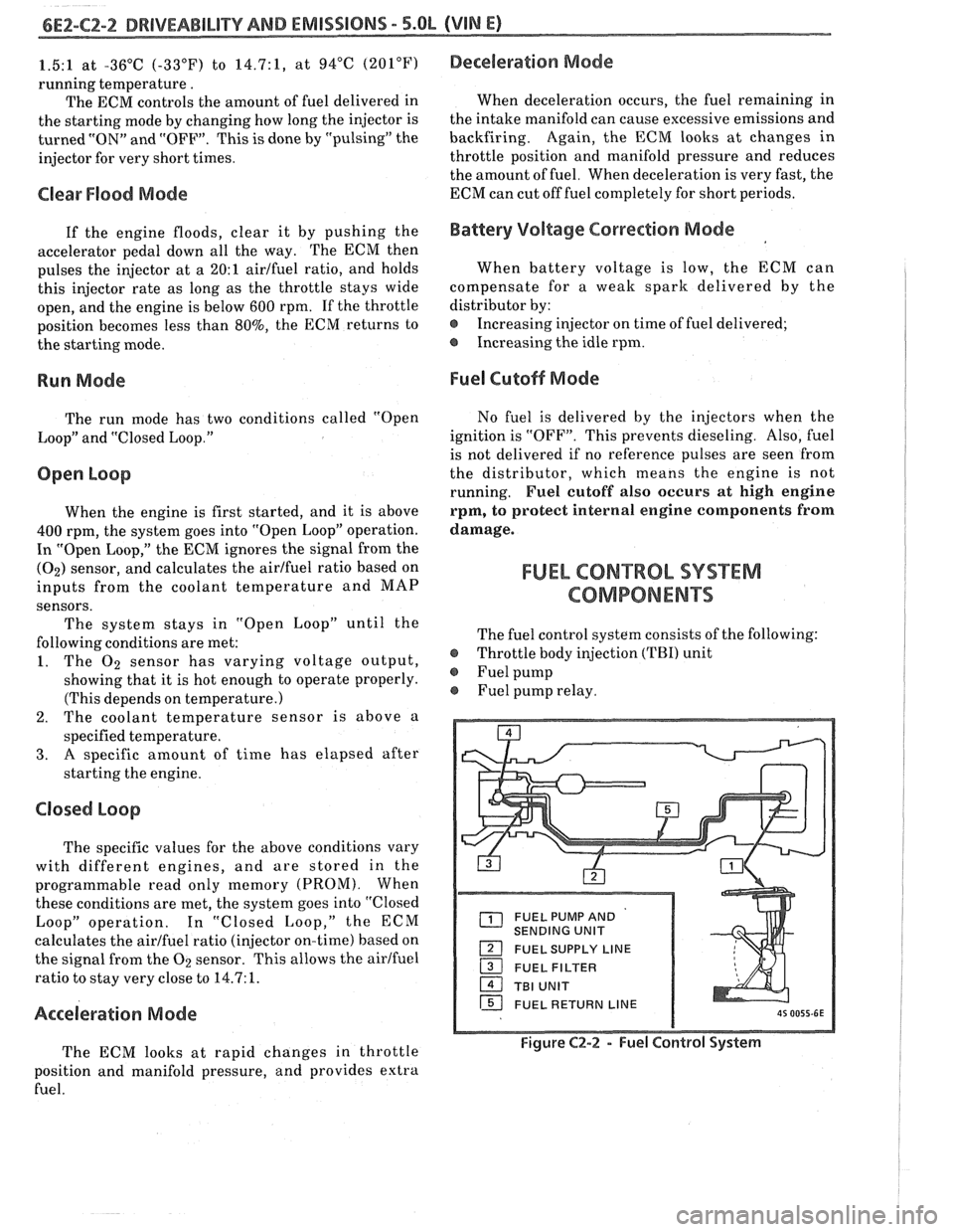
The fuel control system consists of the following:
@ Throttle body injection (TBI) unit
@ Fuel pump
Fuel pump relay.
FUEL PUMP AND
SENDING UNIT
FUEL SUPPLY LINE
16 FUEL RETURN LINE
Figure C2-2 - Fuel Control System
Page 600 of 1825
DRIVEABILITY AND EMISSIONS 5.QL (VIN E) 6Ef-C4-1
SECTION C4
IGNITION SYSTEM 1 (EST)
CQN"FEB\BTO
GENERAL DESCRIPTION ............... C4-1
PURPOSE ........................ C4-1
OPERATION
............*......... C4-1
DIAGNOSIS
........................ C4-1
..... RESULTS OF INCORRECT EST OPER. C4-1
HOW CODE 42 IS DETERMINED ....... C4-2
GENERAL DESCRIPTION
PURPOSE
The High Energy Ignition (HE11 system controls
fuel combustion by providing a spark to ignite the
compressed
aidfuel mixture at the correct time. To
provide improved engine performance, fuel economy,
and control of exhaust emissions, the ECM controls
distributor spark advance (timing) with the Electronic
Spark Timing (EST) system.
Only the Electronic Spark 'Timing (EST) system
will be described here. Additional information on the
HE1 system is found in Section 6D.
OPERATION
The standard high energy ignition (HEI) system
(described in Section 6D) has a modified distributor
module, which is used in connection with EST.
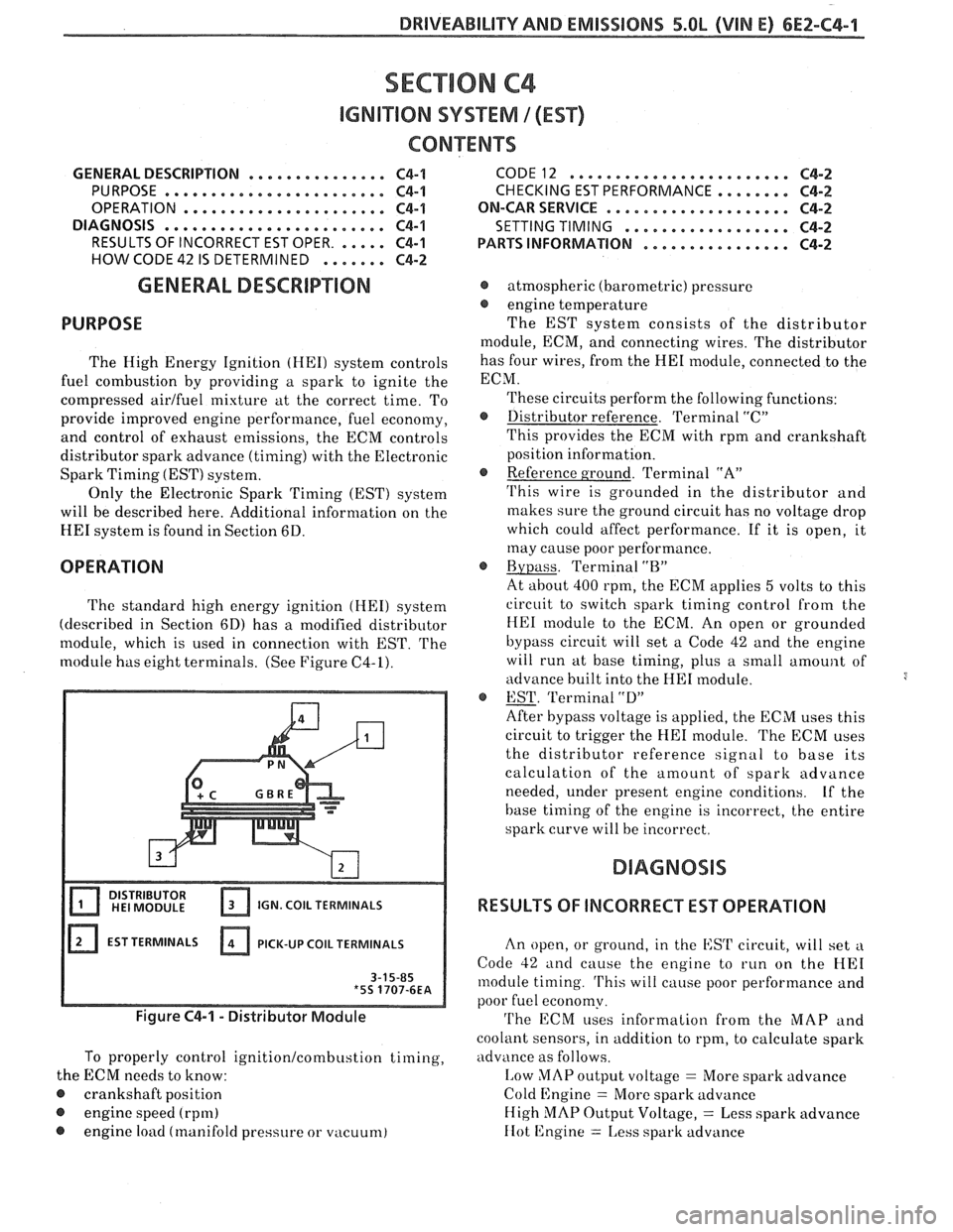
The
module has eight terminals. (See Figure C4-1).
IGN. COIL TERMINALS
EST TERMINALS PICK-UP
COIL TERMINALS
Figure C4-1 - Distributor Module
To properly control ignition/combustion timing,
the ECM needs to know:
@ crankshaft position
@ engine speed (rpm)
@ engine load (manifold pressure or vacuum)
CODE12 ........................ C4-2
CHECKING EST PERFORMANCE ........ C4-2
ON-CAR SERVICE ...a.e.............. C4-2
SETTING TIMING
.................. C4-2
PARTSINFORMATION ................ C4-2
@ atmospheric (barometric) pressure
@ engine temperature
The EST system consists of the distributor
module, ECM, and connecting wires. The distributor
has four wires, from the
HE1 module, connected to the
ECM.
These circuits perform the following functions:
@ Distributor reference. Terminal "C"
This provides the ECM with rpm and crankshaft
position information.
@ Reference ground. Terminal "A"
'I'his wire is grounded in the distributor and
makes sure the ground circuit has no voltage drop
which could affect performance. If it is open, it
may cause poor performance.
@ Bypass. Terminal "BJ'
At about 400 rpm, the ECM applies 5 volts to this
circuit to switch spark timing control
from the
HE1 module to the ECM. An open or grounded
bypass circuit will set a Code 42 and the engine
will run at base timing, plus a small
amount of
advance built into the
HE1 module.
@ EST. 'Terminal "D"
After bypass voltage is applied, the ECM uses this
circuit to trigger the
HE1 module. The ECM uses
the distributor reference signal to base its
calculation of the amount of spark advance
needed, under present engine conditions.
Lf the
base timing of the engine is incorrect, the entire
spark curve will be incorrect.
RESULTS OF INCORRECT EST OPERATION
An open, or ground, in the EST circuit, will set a
Code 42 and cause the engine to run on the HE1
module timing. 'I'his will cause poor performance and
poor fuel economy.
'I'he ECM uses information from the MAP and
coolant sensors, in addition to rpm, to calculate spark
advance as follows.
I,ow MAP output voltage = More spark advance
Cold Engine
= More spark advance
High
MAP Output Voltage, = Less spark advance
IIot 12ngine = 1,ess spark advance
Page 603 of 1825
6E2-C4-4 5.OL (VIN E) DRIVEABILITY AND EMISSIONS
CONNECTOR
430 PPUWHf
424 TANIBLK
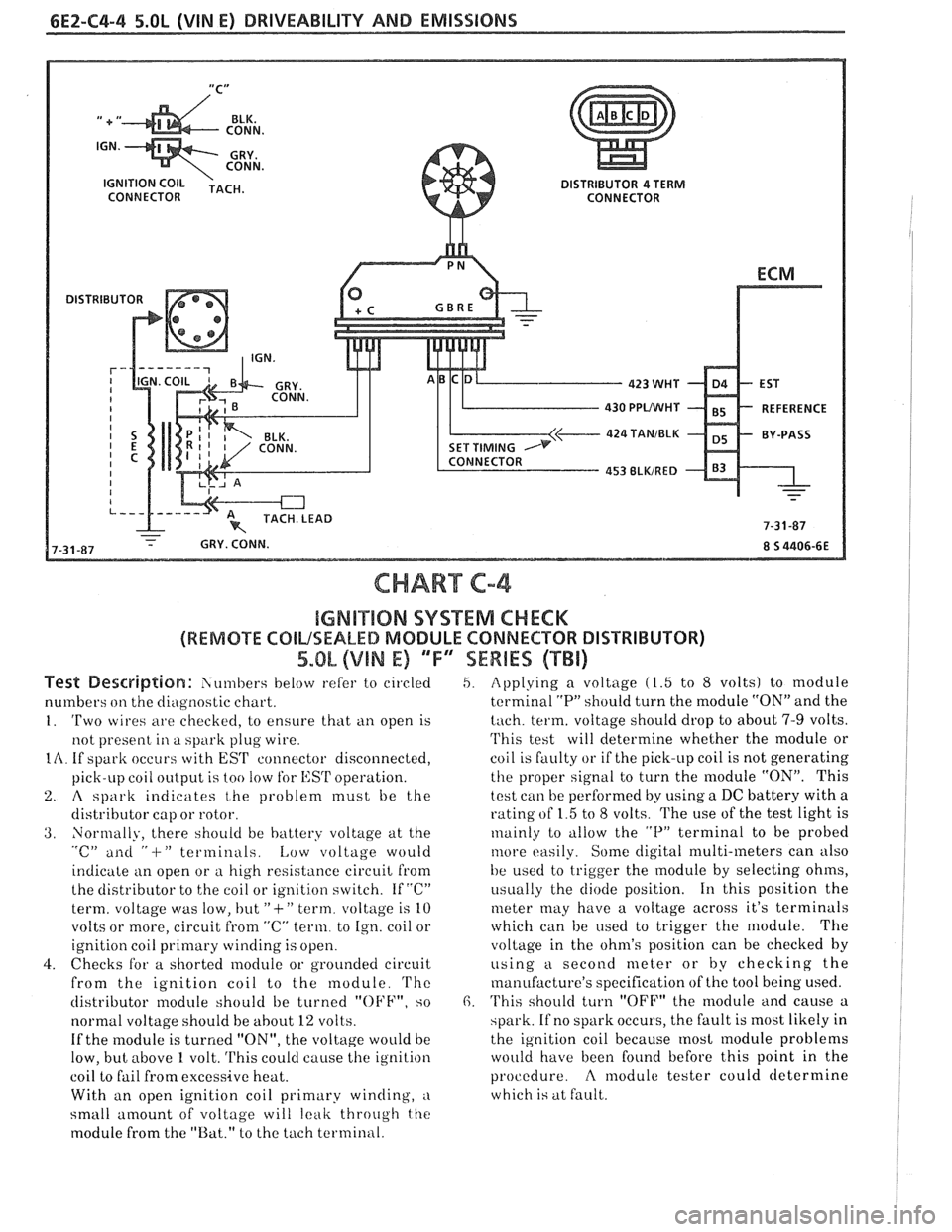
CHART C-4
IGMB"$IIQN SYSTEM CHECK
(REMOTE COILSEALED MODULE CONNECTOR DISTRIBUTOR)
5.OL (VIN E) 'TF"7SEWBES (TBi)
Test De~driptian: Siin~bers below refer to circled
numbers
on the diagilostic chart.
1. 'Two wires are checkecl, to ensure that ti11 open is
not present
in a spark plug wire.
IA. If spark occurs with EST connector disconnected,
pick-LIP coil
oiltp~it is too !OW for l,:SrI' operation.
2. A spark indicates t,he problem must be the
distributor cap or rotor.
3. Normally, there should be battery voltage at the "c" ailti " -I-" terminals. Low voltage would
indicate an open or
a high resistance circuit from
the distributor to the coil or ignition switch. If "C"
term. voltage was low, but
"+" term. voltage is 10
volts or more, circuit
from "C" term. to Ign. coil or
ignition coil
primary winding is open.
4. Checks for a shorted module or grounded circuit
from the ignition coil to the module.
'I'hc
distributor module should be turned "OFF", so
normal voltage should be
about 12 volts.
If the module is turned "ON", the voltage would be
low, but above
1 volt. This could cause the ignition
coil to fail from excessive heat.
With an open ignition coil primary winding,
a
small amount of voltage will leak throtrgh the
module from the "Bat." to the tach terminal.
5. Applying a voltage (1.5 to 8 volts) to module
terminal
"P" should turn the module "ON" and the
tach. term. voltage should drop to about 7-9 volts.
'I'his test will determine whether the module or
coil is faulty or if the pick-up coil is not generating
the proper signal to turn the module "ON". This
test can be performed by using a DC battery with a
rating of 1.5 to
8 volts. The use of the test light is
~nainly to tillow the "P" terminal to be probed
tilore easily. Some digital multi-meters can also
be used to trigger the
module by selecting ohms,
i~sually the diode position. 111 this position the
meter may have a voltage across it's terminals
which can be
used to trigger the module. The
voltage in the ohm's position can be checked
by
using a second meter or by checking the
manufacture's specification of the tool being used.
6. 'I'his should turn "OFF" the module and cause a
spark. If no spark occurs, the fault is most likely in
the ignition coil because
most module problems
would have been found before this point in the
procedure.
A modulc tester could determine
which is at fault.
Page 643 of 1825
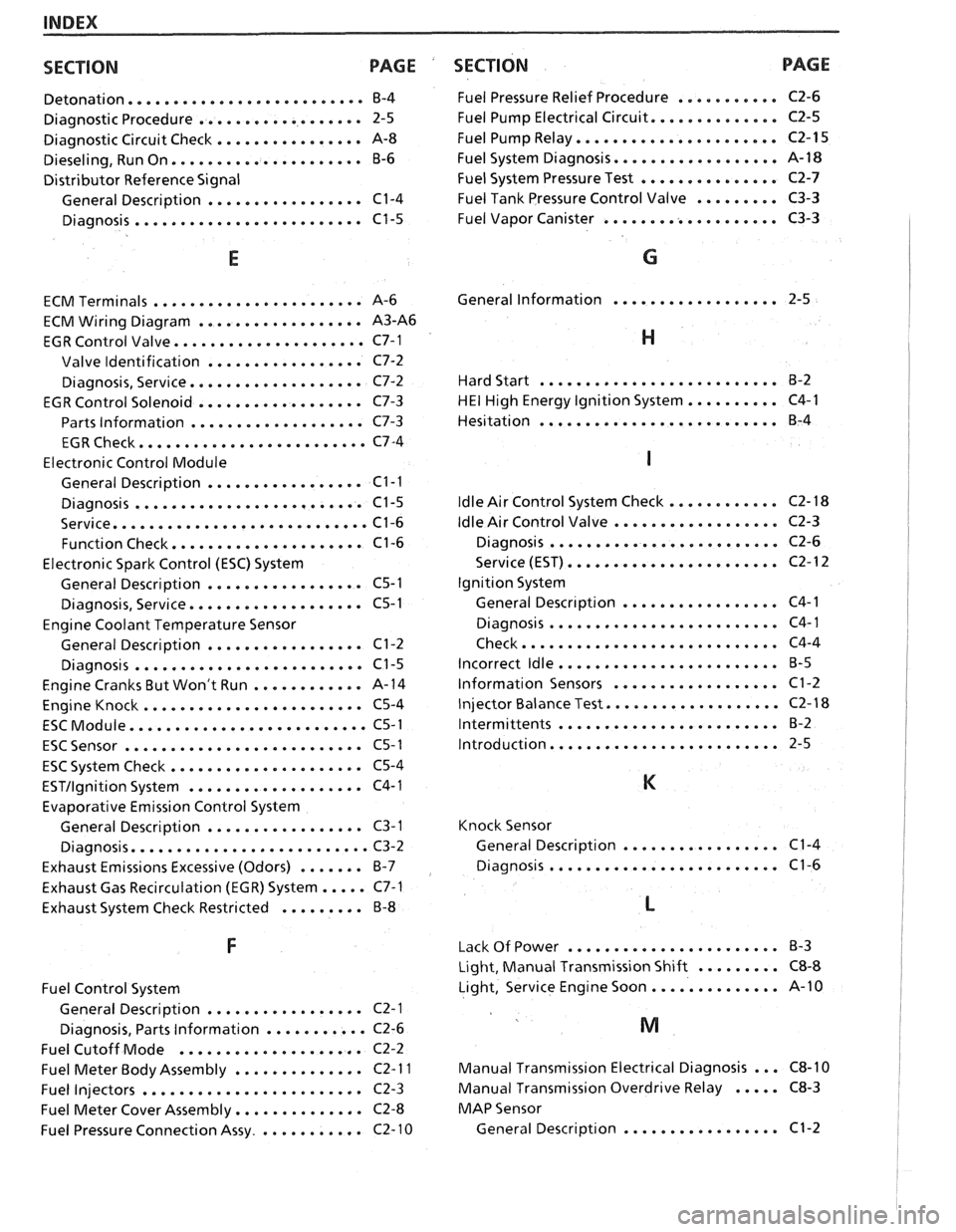
INDEX
SECTION PACE
....................... Detonation... B-4
.................. Diagnostic Procedure 2-5
................ Diagnostic Circuit Check A-8
..................... Dieseling. Run On B-6
Distributor Reference Signal
................. General Description C1-4
......................... Diagnosis C1-5
E
.................... ECM Terminals ... A-6
.................. ECM Wiring Diagram A3-A6
..................... EGR Control Valve C7-1
................. Valve Identification C7-2
................... Diagnosis. Service C7-2
EGR Control Solenoid
.................. C7-3
Parts Information
................... C7-3
......................... EGR Check C7-4
Electronic Control Module
................. General Description C1-I
......................... Diagnosis C1-5
............................ Service C1-6
..................... Function Check C1-6
Electronic Spark Control (ESC) System
................. General Description C5-1
................... Diagnosis. Service C5-I
Engine Coolant Temperature Sensor
................. General Description C1-2
......................... Diagnosis C1-5
Engine Cranks But Won't Run
............ A-14
........................ Engine Knock C5-4
.......................... ESC Module C5-1
.......................... ESC Sensor C5-1
..................... ESC System Check C5-4
ESTIlgnition System ................... C4-1
Evaporative Emission
Conirol System
General Description
................. C3-1
.......................... Diagnosis C3-2
Exhaust Emissions Excessive (Odors)
....... B-7
Exhaust Gas Recirculation (EGR) System
..... C7-1
Exhaust System Check Restricted
......... B-8
Fuel Control System
General Description
................. C2-1
Diagnosis. Parts Information
........... C2-6
Fuel Cutoff Mode
.................... C2-2
Fuel Meter Body Assembly
.............. C2- 1 I
Fuel Injectors ........................ C2-3
Fuel Meter Cover Assembly
.............. C2-8
Fuel Pressure Connection Assy
............ C2- 10
SECTION PAGE
........... Fuel Pressure Relief Procedure C2-6
.............. Fuel Pump Electrical Circuit C2-5
...................... Fuel Pump Relay C2-15
.................. Fuel System Diagnosis A- 18
............... Fuel System Pressure Test C2-7
......... Fuel Tank Pressure Control Valve C3-3
................... Fuel
Vapor Canister C3-3
G
.................. General Information 2-5
H
.......................... Hard Start B-2
.......... HE1 High Energy Ignition System C4-1
.......................... Hesitation
B-4
............ ldle Air Control System Check
.................. ldle Air Control Valve
......................... Diagnosis
....................... Service (EST)
Ignition System
................. General Descr~ption
......................... Diagnosis
Check
............................
........................ Incorrect ldle
.................. lnformation Sensors
................... Injector Balance Test
........................ Intermittents
......................... Introduction
Knock Sensor
................. General Description C1-4
......................... Diagnosis C1-6
....................... Lack Of Power B-3
Light. Manual Transmission Shift
......... C8-8
Light. Service Engine Soon
.............. A-10
Manual Transmission Electrical Diagnosis
... C8-10
Manual Transmission Overdrive Relay ..... C8-3
MAP Sensor
General Description
................. C1-2
Page 647 of 1825
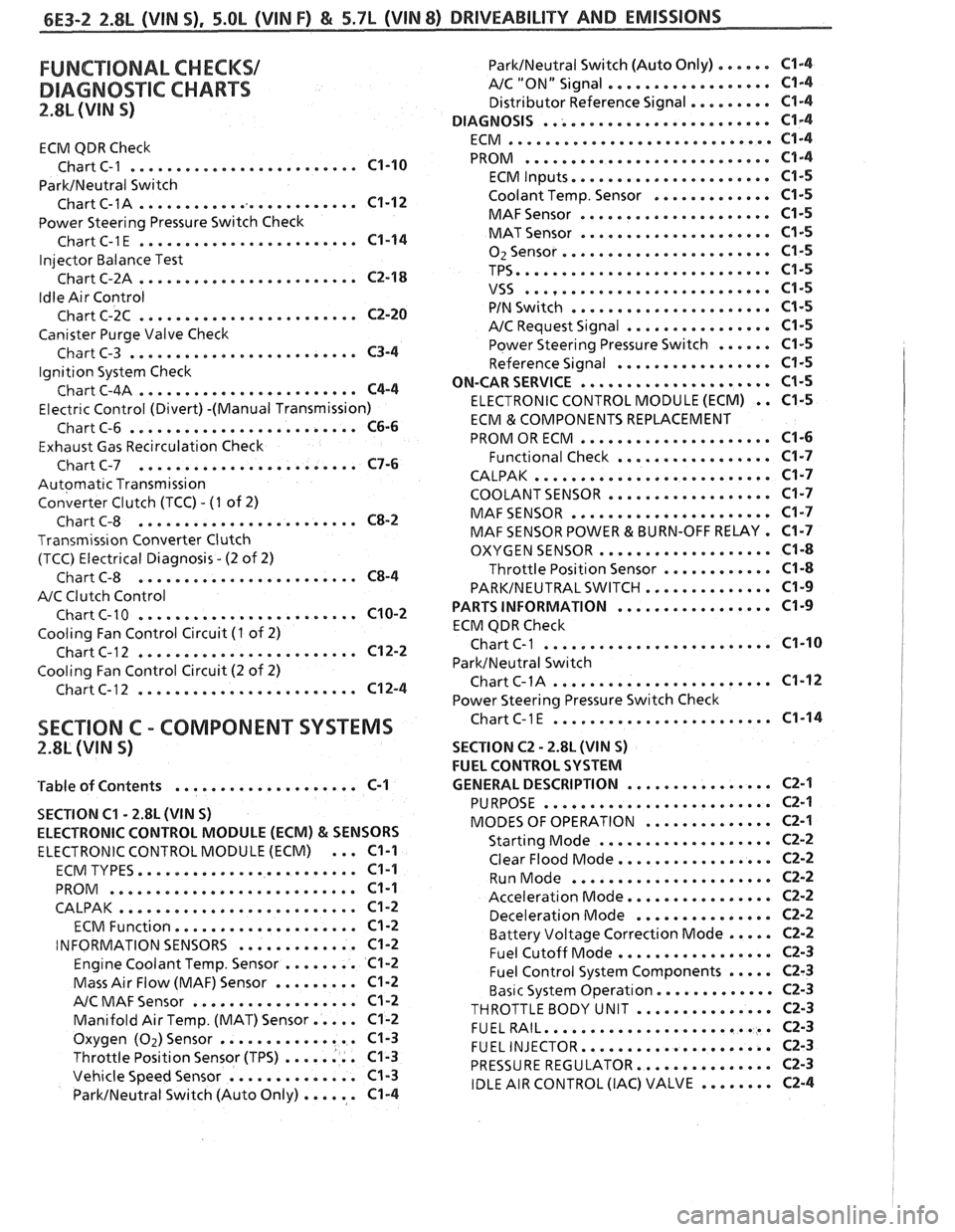
FUNCTIONAL CHECKS/
DIAGNOSTIC CHARTS
2.8L (VIN S)
ECM QDR Check
......................... Chart C-1 C1-10
ParkINeutral Switch
......................... Chart C-1A C1-12
Power Steering Pressure Switch Check
........................ ChartC-1E C1-14
Injector Balance Test
........................ Chart C-2A C2-18
Idle Air Control
........................ Chart C-2C C2-20
Canister Purge Valve Check
......................... Chart C-3 C3-4
Ignition System Check
........................ Chart C-4A C4-4
Electr~c Control (Divert) -(Manual Transmission)
......................... Chart C-6 C6-6
Exhaust Gas Recirculation Check
........................ Chart C-7 C7-6
Automatic Transmission
Converter Clutch (TCC)
. (I of 2)
........................ Chart C-8 C8-2
Transmiss~on Converter Clutch
(TCC) Electrical Diagnosis
. (2 of 2)
........................ Chart C-8 C8-4
A/C Clutch Control
........................ Chart C-10 C10-2
Cooling Fan Control Circuit (I of 2)
........................ Chart C-12 C12-2
Cooling Fan Control Circuit (2 of 2)
........................ Chart C-12 C12-4
ParklNeutral Switch (Auto Only) ...... C1-4
AIC "ON" Signal .................. C1-4
Distributor Reference Signal ......... C1-4
......................... DIAGNOSIS C1-4
............................. ECM C1-4
........................... PROM C1-4
...................... ECM Inputs C1-5
Coolant Temp . Sensor ............. C1-5
..................... MAFSensor C1-5
..................... MAT Sensor C1-5
....................... 02Sensor C1-5
TPS ............................ C1-5
........................... VSS C1-5
...................... PIN Switch C1-5
................ A/C Request Signal C1-5
Power Steering Pressure Switch ...... C1-5
................. Reference Signal C1-5
ON-CAR SERVICE ..................... C1-5
ELECTRONIC CONTROL MODULE (ECM) . . C1-5
ECM & COMPONENTS REPLACEMENT
..................... PROM OR ECM C1-6
................. Functional Check C1-7
CALPAK .......................... C1-7
COOLANT SENSOR .................. C1-7
MAFSENSOR ...................... C1-7
MAF SENSOR POWER & BURN-OFF RELAY . C1-7
................... OXYGEN SENSOR C1-8
Throttle Position Sensor ............ C1-8
PARKINEUTRALSWITCH .............. C1-9
................. PARTS INFORMATION C1-9
ECM QDR Check
................... ... Chart C-1 ... C1-10
ParktNeutral Switch
........................ ChartC-1A C1-12
Power Steering Pressure Switch Check
........................ SECTION C . COMPONENT SYSTEMS ChartC-lE C1-14
2.8L (VIN S) SECTION C2 . 2.8L (WIN S)
FUEL CONTROL SYSTEM
................ 'Table of Contents .................... C-1 GENERAL DESCRIPTION C2-1
SECTION
C1 . 2.8L (VIN S)
ELECTRONIC CONTROL MODULE (ECM)
& SENSORS
ELECTRONIC CONTROL MODULE (ECM) ... C1-1
........................ ECM TYPES C1-1
........................... PROM C1-1
CALPAK .......................... C1-2
.................... ECM Function C1-2
............. INFORMATION SENSORS C1-2
Engine Coolant Temp . Sensor ........ C1-2
Mass Air Flow (MAF) Sensor ......... C1-2
.................. A/C MAF Sensor Cl-2
Manifold Air Temp . (MAT) Sensor ..... C1-2
Oxygen (Oz)Sensor ............... C1-3
Throttle Position Sensor (TPS) ........ C1-3
Vehicle Speed Sensor .............. C1-3
ParkINeutral Switch (Auto Only) ...... C1-4
......................... PURPOSE C2-1
.............. MODES OF OPERATION C2-1
................... Starting Mode C2-2
................. Clear Flood Mode C2-2
...................... Run Mode C2-2
................ Acceleration Mode C2-2
............... Deceleration Mode C2-2
Battery Voltage Correction Mode ..... C2-2
................. Fuel Cutoff Mode C2-3
Fuel Control System Components ..... C2-3
Basic System Operat~on ............. C2-3
THROTTLEBODY UNIT ............... C2-3
......................... FUELRAIL C2-3
..................... FUEL INJECTOR C2-3
............... PRESSURE REGULATOR C2-3
IDLE AIR CONTROL (IAC) VALVE ........ C2-4
Page 650 of 1825
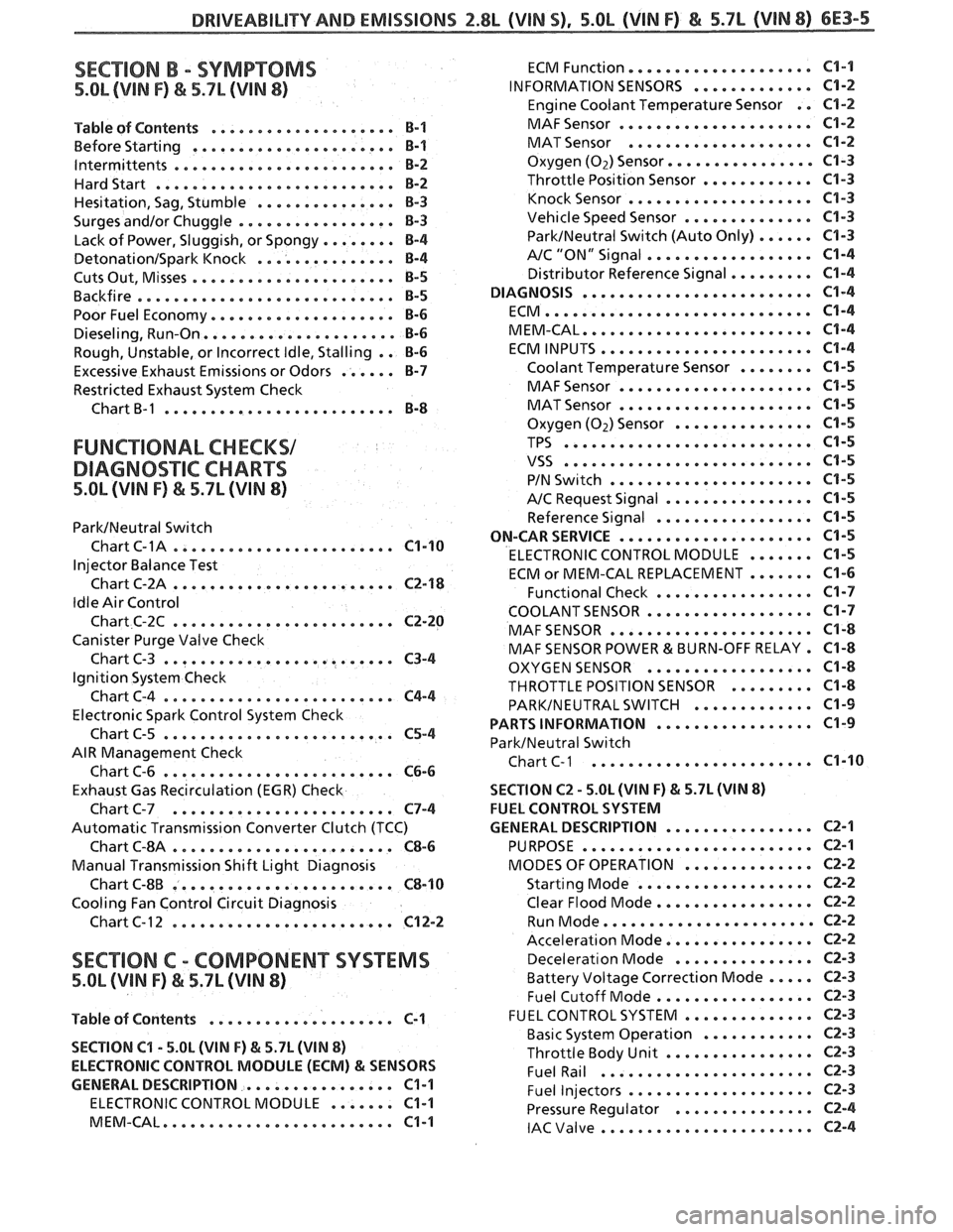
DRIVEABILITVAND EMISSIONS Z.$L (VIN 5). 5.OL (VIN F) & 5.7L (VIN 8) 6E3-5
SECTION B . SYMPTOMS
5.OL (VIN F) & 5.7L (VIN 8)
.................... Table of Contents B-1
................... Before Starting ... B-1
. lntermittents .................... ... B-2
Hardstart .......................... B-2
............... Hesitation. Sag. Stumble 8-3
Surges andlor Chuggle ................. B-3
........ Lack of Power. Sluggish. or Spongy 8-4
DetonationISpark Knock ............... B-4
...................... Cuts Out. Misses €3-5
Backfire ............................ B-5
Poor Fuel Economy .................... B-6
Dieseling. Run.On ..................... 8-6
Rough. Unstable. or Incorrect Idle. Stalling . . B-6
Excessive Exhaust Emissions or Odors ...... B-7
Restricted Exhaust System Check
Chart
B-1 ......................... B-8
FUNCTIONAL CHECKS1
DIAGNO%"FIC CHARTS
5.OL (VIN F) & 5.7L (WIN 8)
ParkINeutral Switch
. Chart C-1A .................... ... C1-10
Injector Balance Test
Chart C-2A
........................ C2-18
Idle Air Control
Chart C-2C
........................ C2-20
Canister Purge Valve Check
Chart C-3
......................... C3-4
Ignition System Check
ChartC-4
......................... C4-4
Electronic Spark Control System Check
Chart C-5
......................... C5-4
AIR Management Check
Chart C-6
......................... C6-6
Exhaust Gas Recirculation (EGR) Check
Chart C-7
........................ C7-4
Automatic Transmission Converter Clutch (TCC)
Chart
6-814 ........................ C8-6
Manual Transmission Shift Light Diagnosis
Chart C-8B
........................ C8-10
Cooling Fan Control Circuit Diagnosis
Chart C- 1 2
........................ C12-2
SECTION C . COMP0NEN"I"SVSTEMS
5.OL (VIN F) & 5.7L (WIN 8)
Table of Contents .................... C-1
SECTION
C1 . 5.OL (VIN F) & 5.7L (VIN 8)
ELECTRONIC CONTROL MODULE (ECM)
81 SENSORS
GENERAL DESCRIPTION
................ C1-1
ELECTRONIC CONTROL MODULE ....... C1-1
MEM.CAL ......................... C1-1
................... ECM Function. C1-1
INFORMATION SENSORS ............. C1-2
Engine Coolant Temperature Sensor . . C1-2
..................... MAF Sensor C1-2
.................... MAT Sensor C1-2
Oxygen (Oz) Sensor ..............a. C1-3
Throttle Position Sensor ............ C1-3
.................... Knock Sensor C1-3
Vehicle Speed Sensor .............. C1-3
ParkINeutral Switch (Auto Only) ...... C1-3
.................. A/C "ON" Signal C1-4
Distributor Reference Signal ......... C1-4
DIAGNOSIS ......................... C1-4
ECM ............................. C1-4
MEM.CAL ......................... C1-4
ECM INPUTS ....................... C1-4
Coolant Temperature Sensor ........ C1-5
..................... MAF Sensor C1-5
..................... MAT Sensor C1-5
Oxygen (Oz) Sensor ............... C1-5
TPS ........................... C1-5
VSS ........................... C1-5
...................... PIN Switch C1-5
A/C Request Signal ................ C1-5
Reference Signal ................. C1-5
ON-CAR SERVICE ..................... C1-5
ELECTRONIC CONTROL MODULE ....... C1-5
ECM or MEM-CAL REPLACEMENT ....... C1-6
Functional Check ................. C1-7
COOLANTSENSOR .................. C1-7
MAF SENSOR ...................... C1-8
MAF SENSOR POWER & BURN-OFF RELAY . C1-8
OXYGEN SENSOR .................. C1-8
THROTTLE POSITION SENSOR ......... C1-8
PARKINEUTRAL SWITCH ............. C1-9
................. PARTS INFORMATION C1-9
ParkINeutral Switch
Chart
C-1 ..................... ... C1-10
SECTION C2 . 5.0L (WIN F) & 5.7L (WIN 8)
FUEL CONTROL SYSTEM
................ GENERAL DESCRIPTION C2-1
......................... PURPOSE C2-1
.............. MODES OF OPERATION CZ-2
................... Starting Mode C2-2
Clear Flood Mode ................. CZ-2
....................... Run Mode CZ-2
................ Acceleration Mode C2-2
............... Decelerat~on Mode C2-3
Battery Voltage Correction Mode ..... C2-3
................. Fuel Cutoff Mode C2-3
.............. FUEL CONTROL SYSTEM C2-3
............ Basic System Operation CZ-3
................ Throttle Body Unit CZ-3
....................... Fuel Rail C2-3
.................... Fuel Injectors CZ-3
............... Pressure Regulator C2-4
....................... IAC Valve 62-4
Page 669 of 1825
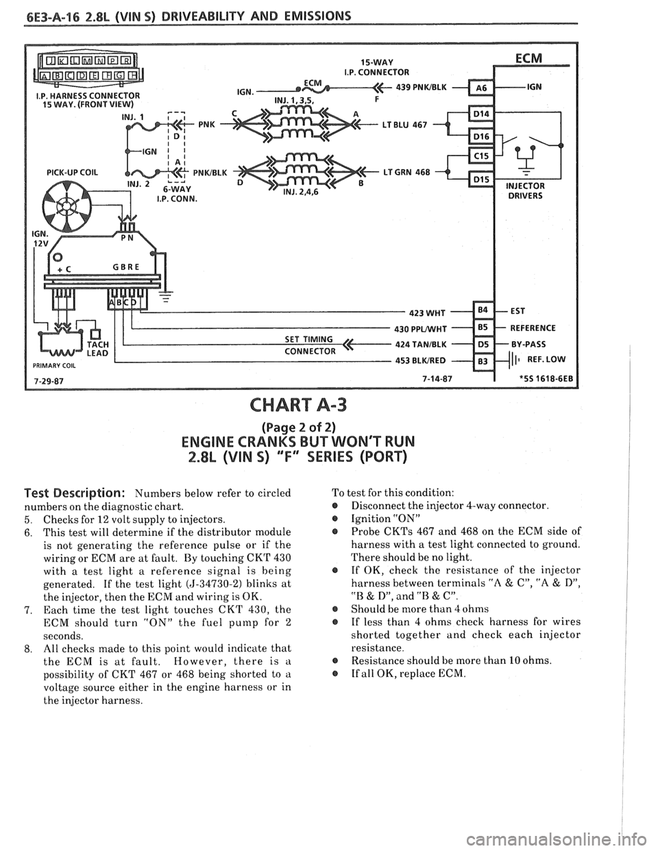
CHART A-3
(Page 2 of 2)
ENGINE CRANKS BUT WONT WN
2.8L (VIN S) ""FYSERIES (PORT)
Test Description: Numbers below refer to circled
numbers on the diagnostic chart.
5. Checks for 12 volt supply to injectors.
6. This
test will determine if the distributor module
is not generating the reference pulse or if the
wiring or ECM are at fault. By touching CKT 430
with a test light a reference signal is being
generated. If the test light
(5-34730-2) blinks at
the injector, then the ECM and wiring is OK.
7. Each time
the test light touches CKT 430, the
ECM should turn "ON" the fuel
punlp for 2
seconds.
8. All
checks made to this point would indicate that
the ECM is at fault. However, there is
a
possibility of CKT 467 or 468 being shorted to a
voltage source either in the engine harness or in
the injector harness. To
test for this condition:
@ Disconnect the injector 4-way connector.
@ Ignition "ON"
Probe
CKTs 467 and 468 on the ECM side of
harness with a test light connected to ground.
There should be no light.
@ If OK, check the resistance of the injector
harness between terminals
"A & C", "A & D",
"B & D", and .'B & C".
@ Should be more than 4 ohms
@ If less than 4 ohms check harness for wires
shorted together and check each injector
resistance.
@ Resistance should be more than 10 ohms.
@ If all OK, replace ECM.