1988 PONTIAC FIERO distributor
[x] Cancel search: distributorPage 367 of 1825
6A2-16 2.8 LITER V-6
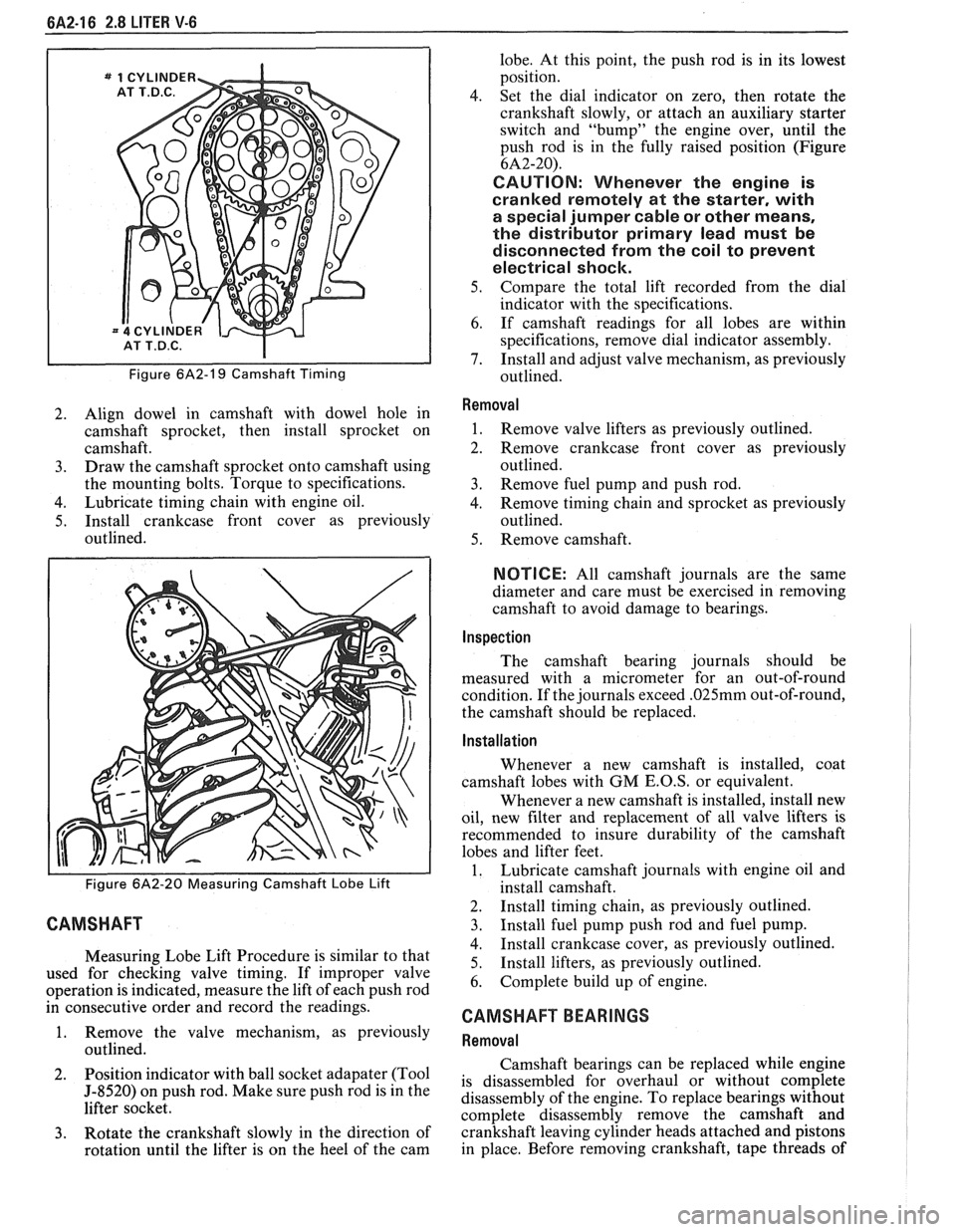
Figure 6A2-19 Camshaft Timing
2. Align dowel in camshaft with dowel hole in
camshaft sprocket, then install sprocket on
camshaft.
3. Draw the camshaft sprocket onto camshaft using
the mounting bolts. Torque to specifications.
4. Lubricate timing chain with engine oil.
5. Install crankcase front cover as previously
outlined.
Figure 6A2-20 Measuring Camshaft Lobe Lift
CAMSHAFT
Measuring Lobe Lift Procedure is similar to that
used for checking valve timing. If improper valve
operation is indicated, measure the lift of each push rod
in consecutive order and record the readings.
1. Remove the valve mechanism, as previously
outlined.
2. Position
indicator with ball socket adapater (Tool
5-8520) on push rod. Make sure push rod is in the
lifter socket.
3. Rotate the crankshaft slowly in the direction of
rotation until the lifter is on the heel of the cam lobe.
At this point, the push rod is in its lowest
position.
4. Set the dial indicator on zero, then rotate the
crankshaft slowly, or attach an auxiliary starter
switch and "bump" the engine over, until the
push rod is in the fully raised position (Figure
6A2-20).
CAUTION: Whenever the engine is
cranked remotely at the starter, with
a special jumper cable or other means,
the distributor primary lead must be
disconnected from the coil to prevent
electrical shock.
5. Compare the total lift recorded from the dial
indicator with the specifications.
6. If camshaft readings for all lobes are within
specifications, remove dial indicator assembly.
7. Install and adjust valve mechanism, as previously
outlined.
Removal
1. Remove valve lifters as previously outlined.
2. Remove crankcase front cover as previously
outlined.
3. Remove fuel pump and push rod.
4. Remove timing chain and sprocket as previously
outlined.
5. Remove camshaft.
NOTICE: All camshaft journals are the same
diameter and care must be exercised in removing
camshaft to avoid damage to bearings.
Inspection
The camshaft bearing journals should be
measured with a micrometer for an out-of-round
condition. If the journals exceed
.025mm out-of-round,
the camshaft should be replaced.
Installation
Whenever a new camshaft is installed, coat
camshaft lobes with
GM E.O.S, or equivalent.
Whenever a new camshaft is installed, install new
oil, new filter and replacement of all valve lifters is
recommended to insure durability of the camshaft
lobes and lifter feet.
1. Lubricate camshaft journals with engine oil and
install camshaft.
2. Install timing chain, as previously outlined.
3. Install fuel pump push rod and fuel pump.
4. Install crankcase cover, as previously outlined.
5. Install
lifters, as previously outlined.
6. Complete build up of engine.
CAMSHAFT BEARINGS
Removal
Camshaft bearings can be replaced while engine
is disassembled for overhaul or without complete
disassembly of the engine. To replace bearings without
complete disassembly remove the camshaft and
crankshaft leaving cylinder heads attached and pistons
in place. Before removing crankshaft, tape threads of
Page 368 of 1825
2.8 LITER V-6 6A2-17
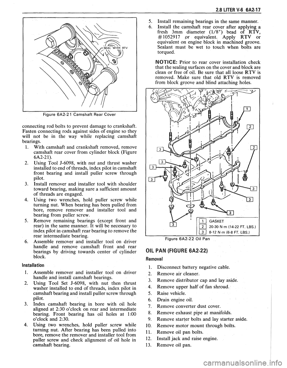
Figure 6A2-2 1 Camshaft Rear Cover
connecting rod bolts to prevent damage to crankshaft.
Fasten connecting rods against sides of engine so they
will not be in the way while replacing camshaft
bearings.
1. With camshaft and crankshaft removed, remove
camshaft rear cover from cylinder block (Figure
6A2-2 1).
2. Using Tool J-6098, with nut and thrust washer
installed to end of threads, index pilot in camshaft
front bearing and install puller screw through
pilot.
3. Install remover and installer tool with shoulder
toward bearing, making sure a sufficient amount
of threads are engaged.
4. Using two wrenches, hold puller screw while
turning nut. When bearing has been pulled from
bore, remove remover and installer tool and
bearing from puller screw.
5. Remove remaining bearings (except front and
rear) in the same manner. It will be necessary to
index pilot in camshaft rear bearing to remove the
rear intermediate bearing.
6. Assemble remover and installer tool on driver
handle and remove camshaft front and rear
bearings by driving towards center of cylinder
block.
Installation
1. Assemble remover and installer tool on driver
handle and install camshaft bearings.
2. Using Tool Set J-6098, with nut then thrust
washer installed to end of threads, index pilot in
camshaft bearing and install puller screw through
pilot.
3. Index camshaft bearing in bore with oil hole
aligned at
2:30 o'clock on rear and intermediate
bearing. Front bearing has oil holes at
1:00
o'clock and 230.
4. Using two wrenches, hold puller screw while
turning nut. After bearing has been pulled into
bore, remove the remover and installer tool from
puller screw and check alignment of oil hole in
camshaft bearing.
5. Install remaining bearings in the same manner.
6. Install the camshaft rear cover after applying a
fresh 3mm diameter
(1/8") bead of RTV,
#I052917 .or equivalent. Apply RTV or
equivalent on engine block in machined groove.
Sealant must be wet to touch when bolts are
torqued.
NOTICE: Prior to rear cover installation check
that the sealing surfaces on the cover and block are
clean or free of oil. Be sure that all loose RTV is
removed. Make sure that old RTV is removed
from block groove and blind attaching holes.
&'p-x&F--
1 20-30 N~rn (14-22 FT. LBS.)
Figure 6A2-22 Oil Pan
OIL PAN (FIGURE 6A2-22)
Removal
1. Disconnect battery negative cable.
2. Remove air cleaner.
3. Remove distributor cap and lay aside.
4. Remove upper half of fan shroud.
5. Raise vehicle.
6. Drain engine oil.
7. Remove converter dust cover.
8. Remove exhaust
pipe at manifolds.
9. Remove starter bolts and lay starter aside.
10. Remove
motor mount through bolts.
1 1. Remove oil pan bolts.
12. Install jack and raise engine.
13. Remove oil pan.
Page 369 of 1825
6A2-18 2.8 LITER V-6
Installation
Clean sealing surfaces on cylinder case and oil
pan.
Install gasket and attach retaining bolts.
Remove jack and lower engine.
Install motor mount through bolts.
Install starter.
Install exhaust pipes.
Install converter dust cover.
Lower vehicle.
Install fan shroud.
Install distributor cap.
Refill crankcase.
Install air cleaner.
Connect battery.
Start engine, check for leaks.
OIL PUMP (FIGURE 6A2-22)
Removal
1. Remove oil pan as previously outlined.
2. Remove pump to rear main bearing cap bolt and
remove pump and extension shaft.
Disassembly
1. Remove
the pump cover attaching bolts and the
pump cover. Mark gear teeth so they may be
reassembled with the same teeth indexing.
2. Remove the idler gear and the drive gear and
shaft from the pump body.
3. Remove the pressure regulator valve retaining
pin pressure regulator spring and valve.
4. If the pickup screen and pipe assembly need
replacing, mount the pump in a soft-jawed vise
and extract pipe from pump cover. Do not disturb
the pickup screen on the pipe. This is serviced as
an assembly.
Cleaning and lnspection
1. Wash all parts in cleaning solvent and dry with
compressed air.
2. Inspect the pump body and cover for cracks or
excessive wear.
3. Inspect pump gears for damage or excessive wear.
The pump gears and body are not serviced
separately. If the pump gears or body are
damaged or worn, replacement of the entire oil
pump assembly is necessary.
4. Check the drive gear shaft for looseness in the
pump body.
5. Inspect inside of pump cover for wear that would
permit oil to leak past the ends of the gears.
6. Inspect the pickup screen and pipe assembly for
damage to screen or pipe.
7. Check the pressure regulator valve for fit.
Assembly
1. If the pickup screen and pipe assembly was
removed, it should be replaced with a new part.
Loss of press fit condition could result in an air
leak and loss of oil pressure. Mount the pump in
a soft-jawed vise, apply sealer to outside diameter of
swaged end of pipe, and using Tool
J-8369 tap
the pipe in place with a plastic hammer.
NOTICE: Be careful of twisting, shearing or
collapsing pipe while installing in pump.
2. Install the pressure regulator valve and related
parts.
3. Install the drive gear and shaft in the pump body.
4. Install the idler gear in the pump body in the
original orientation.
5. Install cover gasket.
6. Install the pump cover and torque attaching
screws to specifications.
7. Turn drive shaft by hand to check for smooth
operation.
Installation
1. Assemble pump and extension shaft with retainer
to rear main bearing cap, aligning top end of
hexagon extension shaft with hexagon socket
lower end of distributor drive gear.
2. Install pump to rear bearing cap bolt and torque
to specifications.
3. Install oil pan as previously outlined.
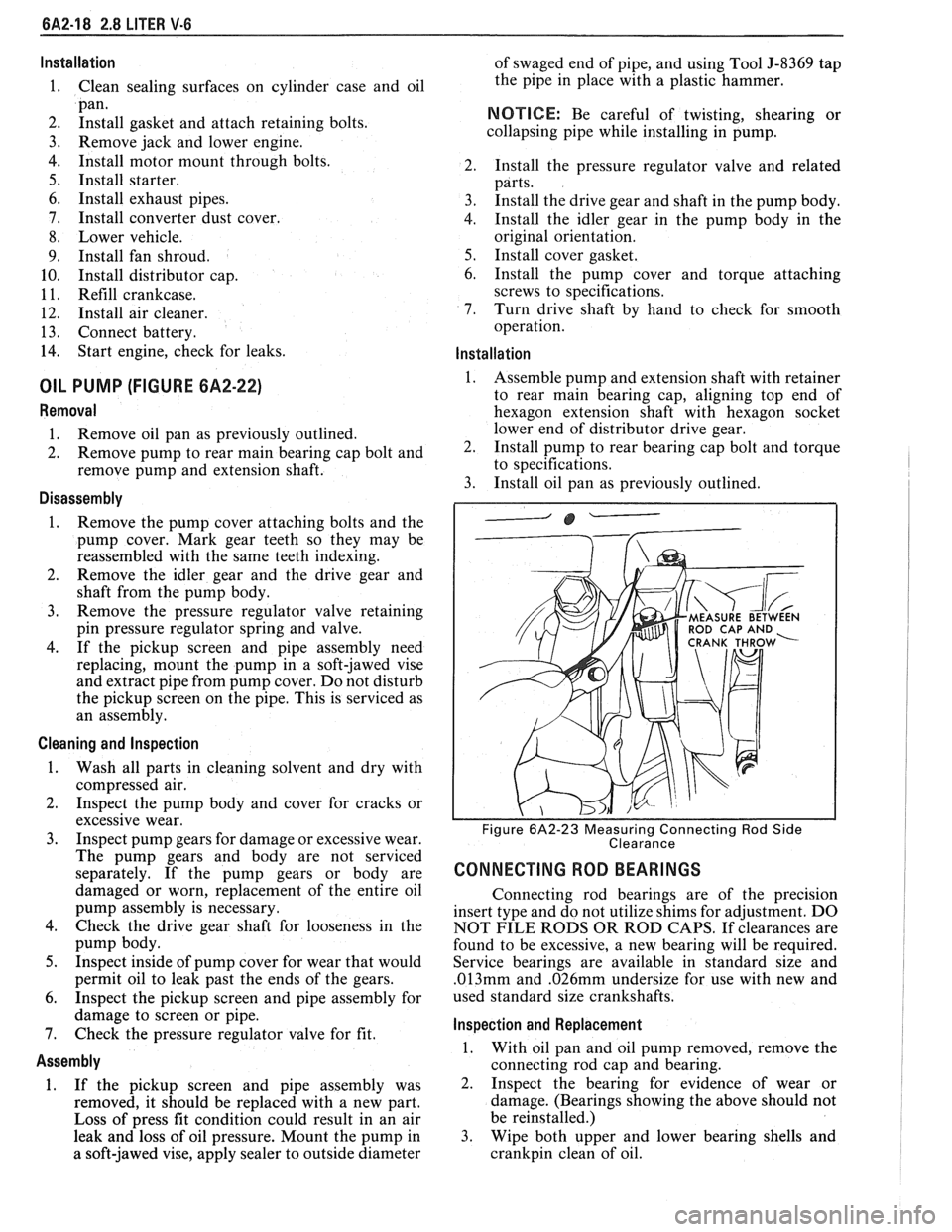
ROD CAP AND
Figure 6A2-23 Measuring Connecting Rod Side
Clearance
CONNECTING ROD BEARINGS
Connecting rod bearings are of the precision
insert type and do not utilize shims for adjustment. DO
NOT FILE RODS OR ROD CAPS. If clearances are
found to be excessive, a new bearing will be required.
Service bearings are available in standard size and
.013mm and .026mm undersize for use with new and
used standard size crankshafts.
lnspection and Replacement
1. With oil pan and oil pump removed, remove the
connecting rod cap and bearing.
2. Inspect the bearing for evidence of wear or
damage. (Bearings showing the above should not
be reinstalled.)
3. Wipe both upper and lower bearing shells and
crankpin clean of oil.
Page 376 of 1825
2.8 LITER V-6 6A2-25
Fitting
1. Select rings comparable in size to the piston being
used.
2. Slip
the compression ring in the cylinder bore;
then press the ring down into the cylinder bore
about 6mm above ring travel. Be sure ring is
square with cylinder wall.
3. Measure the space or gap between the ends of the
ring with a feeler gage (Figure
6A2-33).
4. If
the gap between the ends of the ring is below
specifications, remove the ring and try another
for fit.
5. Fit each compression ring to the cylinder in
which it is going to be used.
6. If the pistons have not been cleaned and inspected
as previously outlined, do so.
7. Slip the outer surface of the top and second
compression ring into the respective piston ring
groove and roll the ring entirely around the
groove (Figure
6A2-34). If binding occurs at any
point, the cause should be determined. If there is
a ring groove, remove by dressing with a fine cut
file. If the binding is caused by a distorted ring,
check a new ring.
Installation
1. Install oil ring spacer in groove being sure ends
are butted and not overlapped.
2. Hold
spacer ends butted and install lower steel oil
ring rail.
3. Install upper
steel oil ring rail with gap staggered.
4. Flex
the oil ring assembly to make sure ring is
free. If binding occurs, the cause should be
detemined. If caused by ring groove, remove by
dressing groove with a fine cut file. If binding is
caused by a distorted ring, check a new ring.
5. Install second compression ring. Stagger gap
from other rings.
6. Install top compression ring with gap properly
located.
ENGINE ASSEMBLY
Removal
Disconnect battery.
Remove air cleaner.
Remove hood. Drain radiator.
Remove lower radiator hose.
Remove upper fan shroud.
Remove upper radiator hose and coolant
recovery hose.
Remove transmission cooler lines. Remove radiator.
Remove fan assembly.
Remove heater hoses.
Disconnect carburetor linkage, includes cruise
control detent cable.
Remove vacuum brake booster line.
Remove distributor cap and lay wiring aside.
Disconnect necessary wires and hoses.
Remove power steering pump and lay aside. Raise
vehicle.
Remove exhaust pipes at exhaust manifold.
Remove dust cover.
Remove converter bolts.
Disconnect starter wires.
Remove bell housing bolts.
Remove motor mount through bolts.
Disconnect fuel lines at fuel pump.
Lower vehicle. Support transmission.
Remove
A.I.R./Converter pipes bracket.
Remove engine, include removing wire from
bracket at rear left of engine.
Installation
Position engine assembly in vehicle.
Attach motor mount to engine brackets and
lower engine in place.
Remove engine lifting device.
Remove transmission floor jack.
Raise vehicle on hoist.
Install mount "through" bolts. Torque to
specifications.
Install bell housing bolts. Torque to
specifications.
On vehicles with automatic transmission, install
converter to flywheel attaching bolts. Torque to
specifications.
Install flywheel splash shield of conveter housing
cover as applicable. Torque attaching bolts to
specifications.
Install starter wires.
Connect fuel lines.
Connect exhaust pipe at manifold.
Lower vehicle on hoist.
Reinstall power steering pump, if so equipped.
Connect necessary wires and hoses.
Install radiator and fan shroud and reconnect
radiator and heater hoses.
Fill cooling system.
Fill crankcase with oil. See owner's manual for
specifications.
Install air cleaner.
Install hood.
Connect battery cables.
NOTICE: To avoid possible arcing of battery,
connect positive battery cable first.
22. Start engine, check for leaks and check timing.
CRANKSHAFT
The crankshaft can be removed while the engine
is dissasembled for overhaul, as previously outlined or
without complete disassembly.
Removal
1. With the engine removed from the vehicle,
remove the clutch assembly (if equipped) and
flywheel. Mount engine in stand and clamp
securely.
Page 381 of 1825
6A3-2 V-8 ENGINE
VALVE TRAIN
A very simple ball pivot-type train is used.
Motion is transmitted from the camshaft through the
hydraulic lifter and push rod to the rocker arm. The
rocker arm pivots on its ball and transmits the
camshaft motion to the valve. The rocker-arm ball is
retained by a nut.
HYDRAULIC VALVE LIFTERS
Hydraulic Valve Lifters are used to keep all parts
of the valve train in constant contact.
The hydraulic lifter assembly consists of: a roller,
the lifter body, which rides in the cylinder block boss,
a plunger, a push rod seat, a metering valve, a plunger
spring, a check ball and spring, a check ball retainer
and a push rod seat retainer.
When the lifter is riding on the low point of the
cam, the plunger spring keeps the plunger and push rod
seat in contact with the push rod.
When the lifter body begins to ride up the cam
lobe, the check ball cuts off the transfer of oil from the
reservoir below the plunger. The plunger and lifter
body then rise as a unit, pushing up the push rod and
opening the valve.
As the lifter body rides down the other side of the
cam, the plunger follows with it until the valve closes.
The lifter body continues to follow the cam to its low
point, but the plunger spring keeps the plunger in
contact with the push rod. The ball check valve will then
move off its seat and the lifter reservoir will
remain full.
INTAKE MANIFOLD
The intake manifold for those engines with
carburetors are made of cast iron or aluminum double
level design for efficient fuel distribution. An Exhaust
Gas Recirculation (EGR) port is also cast into the
manifold for the mixture of exhaust gases with the fuel
air mixture.
The intake manifold for those vehicles equipped
with
PFI is a cast aluminum unit. It centrally supports
a fuel rail with
8 fuel injectors.
EXHAUST MANIFOLDS
Two cast iron exhaust manifolds are used to
direct exhaust gases from the combustion chambers to
the exhaust system. The left hand side manifold
receives a heat shield that is used to route heated air
to the air cleaner. for better fuel vaporization during
warm-up.
COMBUSTION CHAMBERS
Combustion Chambers are cast to insure uniform
shape for all cylinders. Spark plugs are located between
the intake and exhaust valves. The contoured wedge
shape of the combustion chamber minimizes the
possibility of detonation, facilitates breathing and
provides swirling turbulence for smooth, complete
combustion.
ENGINE LUBRICATION
Full pressure lubrication through a full flow oil through drilled passages, to the camshaft and
filter, is furnished by a gear-type oil pump. The crankshaft to lubricate the bearings. The valve lifter oil
distributor, driven by a helical gear on the camshaft,
gallery feeds the valve lifters which, through hollow
drives the oil pump. The main oil gallery feeds oil,
push rods, feed the individually mounted rocker arms.
Page 385 of 1825
6A3-6 V-8 ENGINE
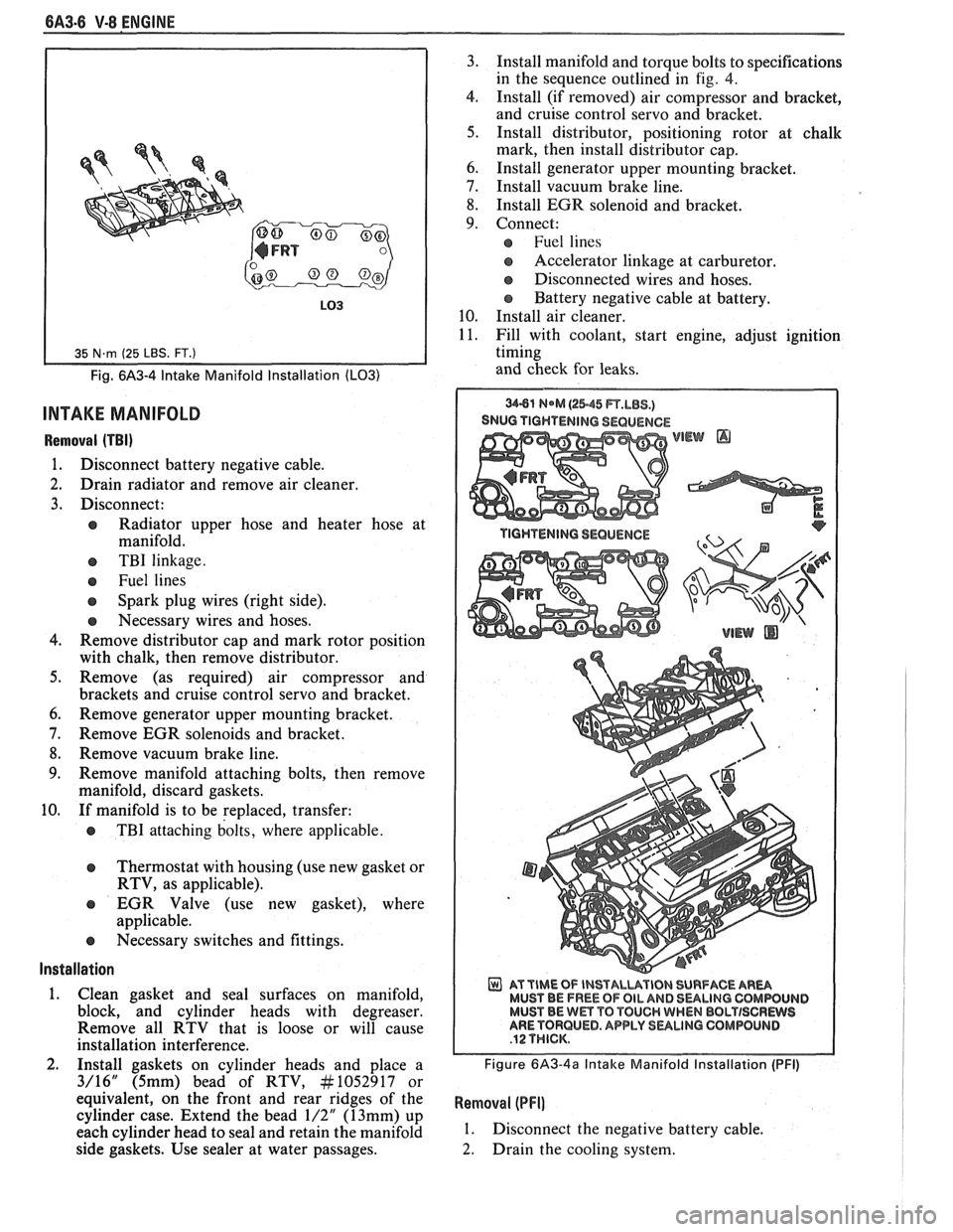
Fig. 6A3-4 Intake Manifold Installation (LO31
INTAKE MANIFOLD
Removal (TBI)
1. Disconnect battery negative cable.
2. Drain radiator and remove air cleaner.
3. Disconnect:
e Radiator upper hose and heater hose at
manifold.
e TBI linkage.
e Fuel lines
Spark plug wires (right side).
e Necessary wires and hoses.
4. Remove distributor cap and mark rotor position
with chalk, then remove distributor.
5. Remove (as required) air compressor and
brackets and cruise control servo and bracket.
6. Remove generator upper mounting bracket.
7. Remove EGR solenoids and bracket.
8. Remove vacuum brake line.
9. Remove manifold attaching bolts, then remove
manifold, discard gaskets.
10. If manifold is to be replaced, transfer:
e TBI attaching bolts, where applicable.
Thermostat with housing (use new gasket or
RTV, as applicable).
EGR Valve (use new gasket), where
applicable.
e Necessary switches and fittings.
lnstallation
1. Clean gasket and seal surfaces on manifold,
block, and cylinder heads with degreaser.
Remove all RTV that is loose or will cause
installation interference.
2. Install gaskets on cylinder heads and place a
3/16" (5mm) bead of RTV, At1052917 or
equivalent, on the front and rear ridges of the
cylinder case. Extend the bead
1/2" (13mm) up
each cylinder head to seal and retain the manifold
side gaskets. Use sealer at water passages. 3.
Install manifold and torque bolts to specifications
in the sequence outlined in
fig. 4.
4. Install (if removed) air compressor and bracket,
and cruise control servo and bracket.
5. Install distributor, positioning rotor at chalk
mark, then install distributor cap.
6. Install generator upper mounting bracket.
7. Install vacuum brake line.
8. Install EGR solenoid and bracket.
9. Connect:
Fuel lines
s Accelerator linkage at carburetor.
@ Disconnected wires and hoses.
Battery negative cable at battery.
10. Install air cleaner.
11. Fill with coolant, start engine, adjust ignition
timing
and check for leaks.
SNUG TIGHTENING SEQUENCE
WEW @
AT TIME OF INSTALUVIBN SURFACE AR- MUST BE FREE OF OIL AND 8ULlNG CQMWUIJD MUST BE Wm TO TOUCH WHEN BBLTISCRWS ARE TORQUED. APPLY SULINO GOMPOLINB
Figure 6A3-4a Intake Manifold Installation (PFI)
Removal (PFI]
1. Disconnect the negative battery cable.
2. Drain the cooling system.
Page 386 of 1825
V-8 ENGINE 6A3-7
-
3. Disconnect accelerator T.V. and cruise cables.
4. Remove air intake duct.
5. Disconnect coolant hoses at throttle body.
6. Disconnect wires at throttle body.
7. Disconnect vacuum and breather hoses at
throttle body.
8. Remove throttle body from plenum.
9. Remove distributor shield.
10. Disconnect brake vacuum hoses at plenum.
1 1. Disconnect vacuum hoses at plenum.
12. Refer to Section 6E3 for removal of:
a Plenum
Fuel Rail
a Cold Start Injector
e Runners
13. Remove distributor.
14. Disconnect EGR solenoid.
15. Disconnect all electrical wires that would
interfere.
16. Remove intake manifold bolts.
17. Remove intake manifold.
Installation
1. Clean all seal surfaces.
2. Install gaskets and place a 3/16 inch 5 (mm) bead
of RTV, No. 1052917 or
equivalent,on the front
and rear ridges of the cylinder case. Extend the
bead 1/2 inch
(13mm) up each cylinder head to
seal and retain the manifold side gaskets and
install intake manifold.
3. Torque manifold bolts to specified torque.
4. Reconnect electrical and vacuum wires.
5. Install distributor.
6. Refer to Section 6E3 for installation
of:
e Plenum
e Fuel Rail
e Cold Start Injectors
a Runners
7. Vacuum hoses at plenum.
8. Install distributor shield.
9. Install throttle body and related parts.
10. Fill cooling system.
1 1. Reconnect battery cable.
12. Start engine and look for leaks.
DIPSTICK TUBE
Removal
1.
Disconnect battery negative cable to prevent
possible contact of the dipstick tube with the
battery terminal on starter during removal.
2. Remove bolt attaching bracket to engine and
remove tube (loose fit).
lnstallation
1. Clean tube and apply sealant #I052080 or
equivalent, around tube
1/2" below bead.
2. Insert tube in block and rotate into position.
3. Install bolt (with starter brace on top of tube
bracket) and connect battery cable.
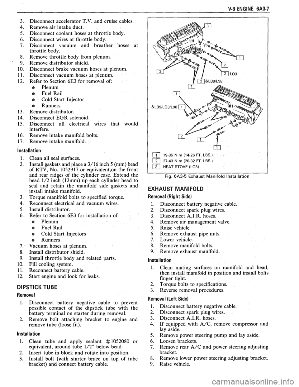
&LB9/LO3/L98
19-35 N.m (14-26 FT. LBS.)
27-43
N.m (20-32 FT. LBS.)
Fig. 6A3-5 Exhaust Manifold lnstallation
EXHAUST MANIFOLD
Removal (Right Side)
1. Disconnect battery negative cable.
2. Disconnect spark plug wires.
3. Disconnect
A.I.R. hoses.
4. Remove air management valve.
5. Raise vehicle.
6. Remove exhaust pipe nuts.
7. Lower vehicle.
8. Remove manifold bolts.
9. Remove exhaust manifold.
lnstallation
1. Clean
mating surfaces on manifold and head,
then install manifold in position and install bolts
finger tight.
2. Torque bolts to specifications.
3. Reverse removal procedures.
Removal (Left Side)
1. Disconnect battery negative cable.
2. Disconnect spark plug wires.
3. Disconnect A.I.R. hoses.
4. If equipped with
A/C, remove compressor and
lay aside.
5. Remove power steering pump and lay aside.
6. Loosen brackets.
7. Remove rear
A/C and power steering adjusting
bracket.
8. Remove lower power steering adjusting bracket.
9. Raise vehicle.
Page 396 of 1825
V-8 ENGINE 6A3.17
4. Set dial indicator on zero, then rotate the
crankshaft slowly, or attach an auxiliary starter
switch and "bump" the engine over, until the
push rod is fully raised position.
e Whenever the engine is cranked remotely at
the started, with a special jumper cable or
other means, the distributor primary lead
should be disconnected from the distributor
(coil).
5. Compare the total lift recorded from the dial
indicator with specifications.
6. If camshaft readings for all lobes are within
specifications, remove dial indicator assembly.
7. Install and adjust valve mechanism as outlined.
Removal
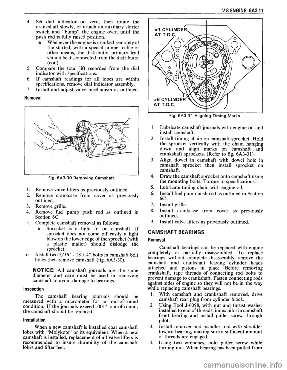
Fig. 6A3-30 Removing Camshaft
1.
Remove valve lifters as previously outlined.
2. Remove crankcase front cover as previously
outlined.
3. Remove grille.
4. Remove fuel pump push rod as outlined in
Section 6C.
5. Complete camshaft removal as follows:
e Sprocket is a light fit on camshaft. If
sprocket does not come off easily a light
blow on the lower edge of the sprocket (with
a plastic mallet) should dislodge the
sprocket.
6. Install two 5/16" - 18 x 4" bolts in camshaft bolt
holes then remove camshaft (fig. 6A3-30).
NOTICE: All camshaft journals are the same
diameter and care must be used in removing
camshaft to avoid damage to bearings.
Inspection
The camshaft bearing journals should be
measured with a micrometer for an out-of-round
condition. If the journals exceed
.001" out-of-round,
the camshaft should be replaced.
Installation
When a new camshaft is installed coat camshaft
lobes with "Molykote" or its equivalent. When a new
camshaft is installed, replacement of all valve lifters is
recommended to insure durability of the camshaft
lobes and lifter feet.
Fig. 6A3-3 1 Aligning Timing Marks
Lubricate camshaft journals with engine oil and
install camshaft.
Install timing chain on camshaft sprocket. Hold
the sprocket vertically with the chain hanging
down and align marks on camshaft and
crankshaft sprockets. (Refer to fig. 6A3-3 1).
Align dowel in camshaft with dowel hole in
camshaft sprocket then install sprocket on
camshaft.
Draw the camshaft sprocket onto camshaft using
the mounting bolts. Torque to specifications.
Lubricate timing chain with engine oil.
Install fuel pump push rod as outlined in Section
6C.
Install grille.
Install crankcase front cover as previously
outlined.
Install valve lifters as previously outlined.
CAMSHAFT BEARINGS
Removal
Camshaft bearings can be replaced with engine
completely or partially disassembled. To replace
bearings without complete disassembly remove the
camshaft and crankshaft leaving cylinder heads
attached and pistons in place. Before removing
crankshaft, tape threads of connecting rod bolts to
prevent damage to crankshaft. Fasten connecting rods
against sides of engine so they will not be in the way
while replacing camshaft bearings.
1. With camshaft and crankshaft removed, drive
camshaft rear plug from cylinder block.
2. Using Tool J-6098, with nut and thrust washer
installed to end of threads, index pilot in camshaft
front bearing and install puller screw through
pilot.
3. Install remover and installer tool with shoulder
toward bearing, making sure a sufficient amount
of threads are engaged.
4. Using two wrenches, hold puller screw while
turning nut. When bearing has been pulled from