1988 PONTIAC FIERO engine oil
[x] Cancel search: engine oilPage 601 of 1825
6E2-C4-2 5.8L (VIN E) DRIVEABILIW AND EMISSIONS
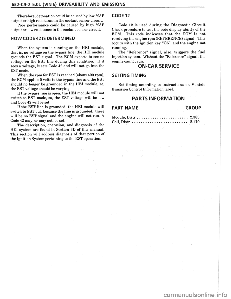
Therefore, detonation could be caused by low MAP
output or high resistance in the coolant sensor circuit.
Poor performance could be caused by high MAP
o~~tput or low resistance in the coolant sensor circuit.
HOW CODE 42 IS DETERMINED
When the system is running on the HE1 module,
that is, no voltage on the bypass line, the
HE1 module
grounds the EST signal. The ECM expects to see no
voltage on the EST line during this condition. If it
sees a voltage, it sets Code
42 and will not go into the
EST mode. When the rpm for EST is reached (about
400 rpm),
the ECM applies 5 volts to the bypass line and the EST
should no longer be grounded in the
HE1 module, so,
the EST voltage should be varying.
If the bypass line is open, the
HE1 module will not
switch to EST mode, so, the EST voltage will be low
and Code
42 will be set.
If the EST line is grounded, the HE1 module will
switch to EST but, because the line is grounded, there
will be no EST signal and the engine will not run. A
Code
42 may, or may not, be set.
The description, operation, and diagnosis of the
HE1 system are found in Section 6D of this manual.
This section will address diagnosis of that portion of
the Ignition System pertaining to the EST operation.
CODE 12
Code 12 is used during the Diagnostic Circuit
Check procedure to test the code display ability of the
ECM. This code indicates that the ECM is not
receiving the engine rpm (REFERENCE) signal. This
occurs with the ignition key
"ON" and the engine not
running.
The "Reference" signal, also, triggers the fuel
injection system. Without the "Reference" signal, the
engine cannot run.
ON-CAR SERVICE
SETTING TIMING
Set timing according to instructions on Vehicle
Emission Control Information label.
PARTS INFORMATION
PART NAME GROUP
....................... Module, Distr 2.383
......................... Coil, Distr 2.170
Page 629 of 1825

6EZ-C8-4 DRIVEABILITY AND EMISSIONS - 5.OL (VIN E)
I5 WAY (FRONT VIEW)
SPEED INPUT
4rH GEAR SIGNAL
422 TANIBLK
ALDL CONNECTOR
CHART C-8A
TRANSMISSION CONVERTER CLUTCH (TCC)
ELECTRICAL DIAGNOSIS
(Page 1 of 2)
5.OL (VIN E) "F" "SERIES (TBI)
Circuit Description:
The purpose of the automatic transmission torque converter clutch is to eliminate the power loss of the
torque converter, when the vehicle is in a cruise condition. This allows the convenience of the automatic
transmission and the fuel economy of a manual transmission.
Fused battery ignition is supplied to the TCC solenoid through the brake switch. the ECM will engage
TCC
by grounding CKT 422 to energize the solenoid.
TCC will engage when:
- Vehicle speed above 24 mph - Engine at normal operating temperature (above 70°C, 156°F)
- Throttle position sensor output not changing, indicating a steady road speed
- Brake switch closed
Test Description: Numbers below refer to circled solenoids
and relays before installing a
numbers on the diagnostic chart. replacement ECM. Replace
any solenoid or relay
1. Confirms 12 volt supply as well as continuity of that
measures less than 20 ohms.
TCC circuit.
2. Grounding the diagnostic terminal with engine Diagnostic Aids:
"OFF", should energize the capability of the ECM An
engine coolant thermostat that is stuck open or
to control the solenoid. opens
at too low a temperature, may result in an
3. Solenoid coil resistance must measure more than inoperative TCC.
20 ohms. Less resistance will cause early failure
of the ECM
drive^.". Using an ohmmeter, check
the solenoid coil resistance of
all ECM controlled
Page 636 of 1825
DRIVEABILITY AND EMISSIONS - 5.OL (VIN E) 6E2-CI 3-1 --
SECTION C13
POSI"BVE CRANKCASE VENTILATION (PCV)
CONTENTS
GENERAL DESCRIPTION ............*.. C13-1 ON-CARSERVICE .................... C13-2
DIAGNOSIS
.*.....................* C13-1 PARTSINFORMATION...,............. C13-2
RESULTS OF INCORRECT OPERATION ... C13-1
GENERAL DESCRIPTION
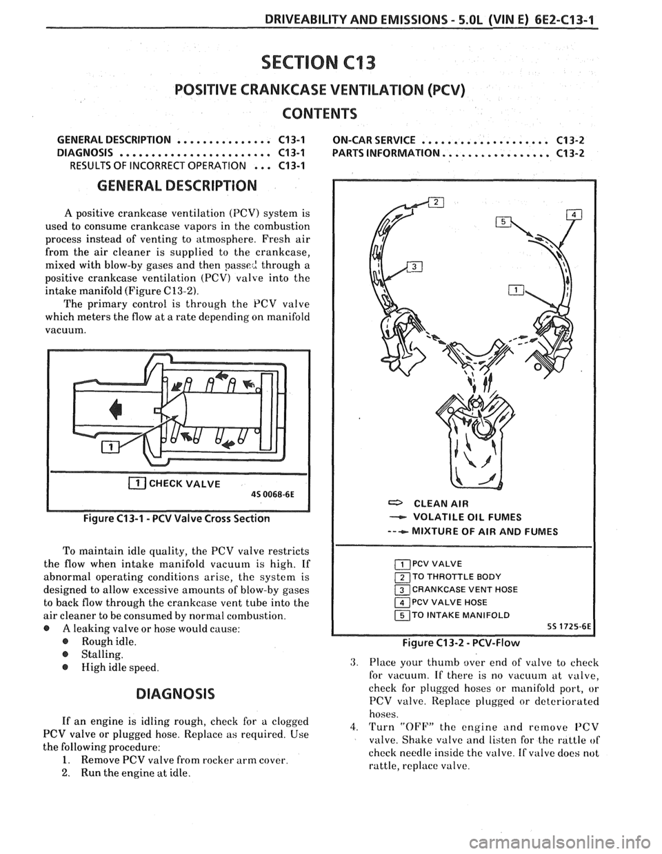
A positive crankcase ventilation (PCV) system is
used to consume crankcase vapors in the combustion
process instead of venting to atmosphere. Fresh air
from the air cleaner is supplied to the crankcase,
mixed with blow-by gases and then
passe2 through a
positive crankcase ventilation
(PCV) valve into the
intake manifold (Figure
C13-2).
The primary control is through the PCV valve
which meters the flow at a rate depending on manifold
vacuum.
CHECKVALVE
a CLEAN AIR
- VOLATILE OIL FUMES
--+ MIXTURE OF AIR AND FUMES
To maintain idle quality, the PCV valve restricts
the flow when intake manifold vacuum is high. If
abnormal operating conditions arise, the system is
TO THROTTLE BODY
designed to allow excessive amounts of blow-by gases CRANKCASE VENT HOSE
to back flow through the crankcase vent tube into the PCV VALVE HOSE
air cleaner to be consumed by normal combustion. TO INTAKE MANIFOLD
@ A leaking valve or hose would cause:
@ Roughidle. Figure C13-2 - PCV-Flow
@ Stalling.
@ High idle speed.
DIAGNOSIS
3. Place your thumb over end of valve to check
for vacuum. If there is no
vacuuin at valve,
check for plugged hoses or manifold port, or
PCV valve. Iteplace plugged or deteriorated
hoses.
If an engine is idling rough, check for a clogged
4. Turn "OFF" the engine and remove PCV PCV valve or plugged hose. Replace as required. Use
valve. Shake valve and listen for the rattle of
the following procedure:
check needle inside the valve. If
valve does not 1. Remove PCV valve from rocker arm cover.
rattle, replace valve.
2. Run the engine at idle.
Page 637 of 1825
6E2-C"1-2 DRIVEABILITY AND EMISSIONS - 5.OL (VIN E)
With this system, any blow-by in excess of the
system capacity (from a badly-worn engine, sustained
heavy load,
etc.) is exhausted into the air cleaner and
is drawn into the engine.
Proper operation of the PCV System is dependent
upon a sealed engine. If oil sludging or dilution is
noted, and the PCV System is functioning properly,
check engine for possible cause and correct to ensure
that system will function as intended.
Results of Incorrect PCV Operation
@ A plugged valve or hose may cause:
@ Rough idle.
@ Stalling or slow idle speed.
Oil leaks.
@ Oil in air clcaner.
@ Sludge in engine.
ON-CAR SERVICE
An engine which is operated without any
crankcase ventilation can be damaged. Therefore, it is
important to replace the
PCV valve and air cleaner
breather at intervals shown in Section
"OB".
Periodically, inspect the hoses and clamps and
replace any showing signs of deterioration.
PARTS INFORMATION
PART NAME GROUP
Air Cleaner ......................... 3.402
................ Valve Asm, UCase Vent 1.745
Page 651 of 1825
6E3-6 2.8L (VIN S). 5.OL (&BIN F) & 5.7L (WIN 8) BRllVEABlhlPY AND EMISSIONS
......... Fuel Pump Electrical Circuit C2-5
DIAGNOSiS ......................... CZ-5
.............. FUEL CONTROL SYSTERA C2.5
............ IDLE AIR CONTROLVALVE CZ-5
......... FUEL SYSTEM PRESSURE TEST C2-5
ON-CAR SERVICE ..................... C2-5
PORT FUEL INJECTION COMPONENTS .... Cf-5
FUEL PRESSURE RELIEF PROCEDURE ..... C2-5
Plenum ......................... C2-5
................ FUEL RAILASSEMBLY CP-6
FUEL RAIL SERVICE ................... C2-7
................... IDENTIFICATION C2-7
........... UNIT SERVICE PROCEDURES C2-7
COLD START .TUBE & VALVE ASSEMBLY ... ~2-7
PARTS INFORMATION ............... CZ-9
.... FUEL PRE5Si.J RE COPdNECl'ION ASSY C2-10
FUEL INJECTORS (Rail Removed) ........ C2-10
PRESSURE REGULATOR (Ball Removed) ... C2-10
COLD START FUEL INJEClION SWITCH ... C2-1%
THROTTLE BODY ................... CZ-11
VWROTTLE BODY SERVICE IDENTIFICATION . C2-12
............ UNIT REPAIR PROCEDURES Cf-112
TPS Adjcistment .............. C2-12
MiNIRilUM IDLE SPEED CHECK ........... CE-'I2
................. PARTS INFORMATION C2-15
IDLE AIR C'NT' L VALVE ASSY (3r: GASKET . . C2-15
CLEAN AIR COVER & GASKET .......... C2-15
SECTION C4 . 5.0h (VIN F) & 5.7L (VIN 8)
lGNITlON SYSTEMIEST
................ GENERAL DESCRIPTION C4-1
......................... PURPOSE C4-1
OPERATION ....................... C4-1
RESULTS OF INCORRECT OPERATION .... C4-1
......................... DIAGNOSIS C4-1
CODE 12 .......................... C4-1
ON-CAR SERVICE ..................... C4-2
SETTING TIMING .................... C4-2
HOW CODE 42 IS DETERMINED ......... C4-2
................. PARTS INFORMATION C4-2
lgn~tion System Check
Chart C-4
......................... C4-4
SECTION C5 . 5.0L (VIM F) & 5.7L JVIN 8)
ELECTRONIC SPARK CONTROL (ESC) SYSTEM
................ GENERAL DESCRIPTION C5-1
......................... PURPOSE C5-1
.............. GENERAL DESCRIPTION C5-1
......................... DlAGNOSiS C5-1
..................... ON-CAR SERVICE C5-1
....................... ESCSENSOR 65-1
.......... E4C MODULE AiYD BRACKET 165-2
................. PARTS INFORMATXBM C5-2
Electronic Spark Control
Chiirt C-5 ......................... C5-4
IDLE AIR CBi\~TROVCOOLANl'CVR . AS57 0
Throlrle Body Reinovecl Froti.1 Engine . .
FUEL PUlVlP RELAY ..................
................ OIL PRESSURE 5WETCI-I
P/%RVS INFORMATION .................
Irilector Halarlce Test
Chart
C-2A ........................
Idle Air Control
Chart
C-%C ........................
C2-I 5 SECYlOM Ct; . 5.0L (VlN F) & 5.7L (VIN 8)
62-1 5 A8W INJECTION REACTION (A.I.R.) SYSTEM
C2-16 GENERAL DESCRbPTION ............... CG-I
C2-16 PURPOSE ....................... C6-1
C2-76 OPE RATION ...................... C6-1
AIR COPJTROL PEDES VALVE ......... C6-I
C2-'18 RESULTS OF INCORRECT OPERATION .... C6-2
DIAGNOSIS ........................ C6-2
............. Cf -20 OPERATIONAL CHECKS C6-2
SbCTIBN C3 . 5.0L (VIN F) h 5.7L (V1N 8)
I:itAPORAIIVE EMISSlON CONTROL (EECS) SYSTEM
LZNERA. L DESCRIP'rION ............... C3-'!
PURPOSE ........................ C3-1
VAPOR CANISTER
.............. $3-1
EVAF'OFt/?ITIVE EMISSION SYSTEM .me.e. C3-4
FUEL TANK PRESSURE CONTROL VALVE . . C3-2
IN-'TANK PRESSURE CONTROL VALVE . . 63-2
RESULTS OF IRiCORRECT OPERATIGN .... C3-2
DIAGNOSIS ........................ C3-2
VISUAL CHECK OF CANIS'rkR .......... C3-2
FUNCPIONAL TEST
Vapor
Can~saer Purge Valve ........ C3-9
Tank Pressure Control Valve ..... C3-2
ON-CAR SERVICE ................. C3-3
FUEL VAPOR CANISTER ............ C3-3
CANISTER HOSES.
................... C3-3
PARTS INFORiblAT%BN ................ C3-3
Canister Purge Valve Check
Chart
C-3 ......................... C3-4
...................... Air Pump C6-2
................. Hoses and Pipes C6-3
.................... Check \/alve C6-3
.................... ON-CAR SERVICE C6-3
...................... DRIVE BELT C6-3
AIR INJECTION PUMP ............... C6-3
AIR INJECTION CONTROL
.................. (PEDES) VALVE C6-3
AIR ~NJECTION CIIECK VALVE ......... ~6-4
................ PARTS INFORMATION C6-4
AIR Management Check (PEDES)
........................ Chart C-6 C6-6
SECTlON C7 . 5.OL (VlN F) & 5.7L (VIN 8)
EXHAUST GAS RECIRCULATION {EGR) SYSTEM
GENERAL DESCRIPI'ION ..............*. C7-1
......................... PURPOSE C7-I
OPERATION
....................... C7-1
EGR
CONTROL .................... C7-1
NEGATIVE BACKPRESSURE EGR VALVE . . C7-2
EGR \/ALVE IDEhITIFICATION ........... C7-2
Page 655 of 1825
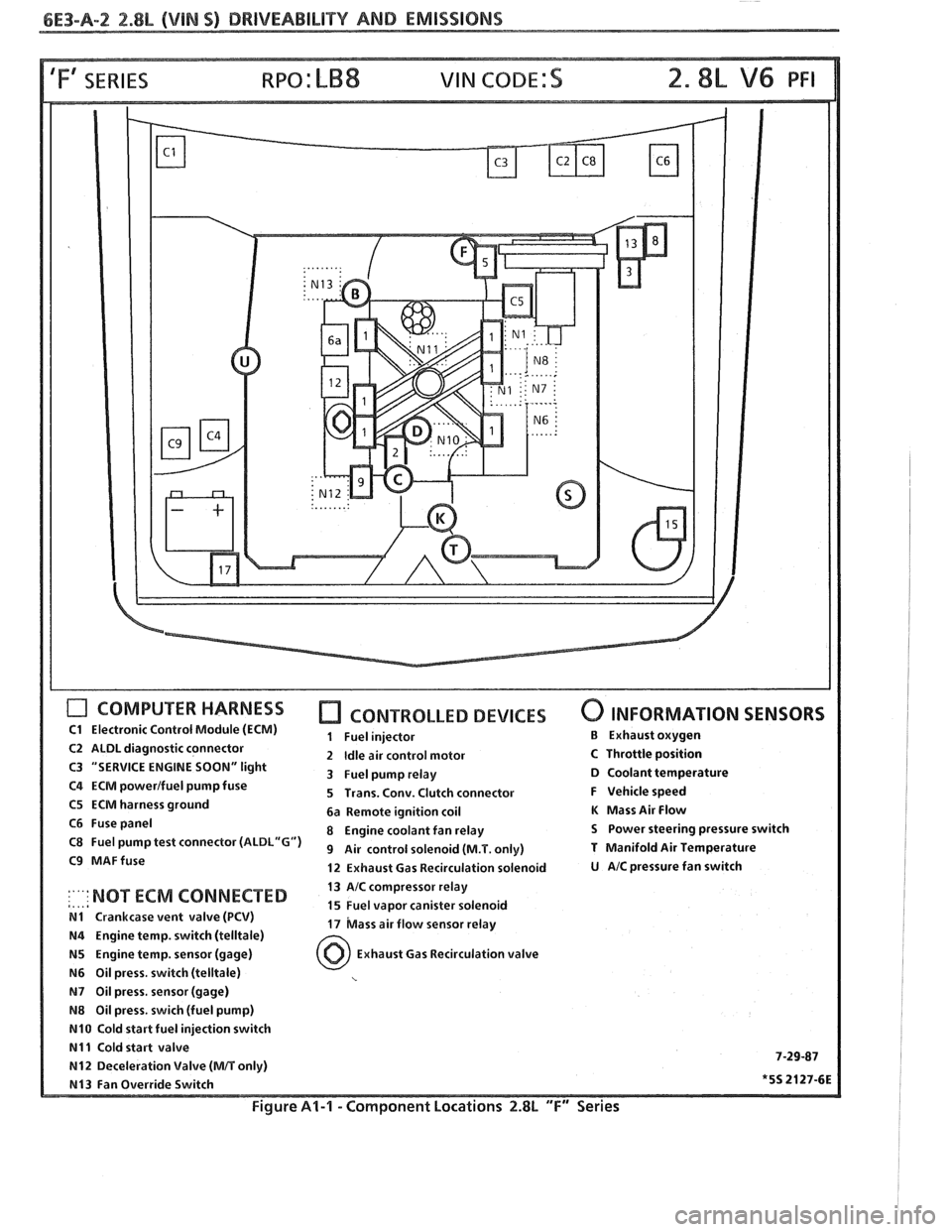
6E3-A-2 2.88, (VIM S) DRIVEABILITY AND EMISSIONS
'Fa SERIES
COMPUTER HARNESS
C1 Electronic Control Module (ECM)
C2 ALDL diagnostic connector
C3 "SERVICE ENGINE
SOON" light
C4 ECM powerlfuel pump fuse
C5 ECM harness ground
C6 Fuse panel
C8 Fuel pump test connector
(ALDL"G")
C9 MAFfuse
CONTROLLED DEVICES
1 Fuel injector
2
Idle air control motor
3 Fuel pump relay
5 Trans. Conv. Clutch connector
6a Remote ignition coil
8 Engine coolant fan relay
9 Air control solenoid (M.T. only)
12 Exhaust Gas Recirculation solenoid
0 INFORMATION SENSORS
B Exhaust oxygen
C Throttle position D Coolant temperature
F Vehicle speed
K Mass Air Flow
S Power steering pressure switch
T Manifold Air Temperature
U AIC pressure fan switch
13 AIC compressor relay
,..,a :'"' NOT ECM 'ONNECTED 15 Fuel vapor canister solenoid N1 Crankcase vent valve (PCV) 17 bass air flow sensor relay N4 Engine temp. switch (telltale)
N5 Engine temp. sensor (gage) Exhaust Gas Recirculation valve
N6 Oil press. switch (telltale)
N7 Oil press, sensor (gage)
N8 Oil press. swich (fuel pump)
N10 Cold start fuel injection switch
N11 Cold start valve 7-29-87 N12 Deceleration Valve (MIT only)
N13 Fan Override Switch *5S 2127-6E
Figure Al-l - Component Locations 2.8L "F" Series
Page 663 of 1825

6E3-A-"I 2.8L (VlN S) DRIVEABILITY AND EMlSSlONS
TO OIL PRESS. SW.
&FUEL PUMP RELAY
FUSE
81 HOLDER BATTERY 12 V .. m.. . n.
. . . . . . . . FUSIBLE LINK
439 PNWBLK
419 BRNNVHT
SERIAL
DATA
451
WHTJBLK
450 BLKNVHT
ALDL CONNECTOR
NO "SERVICE ENGlNE SOON" "LIGHT
2.8b (VIM 5) 'T" "SERIES (PORT)
Circuit Description:
There should always be a steady "Service Engine Soon" light when the ignition is "ON" and engine stopped.
Battery is supplied directly to the light bulb. The electronic control module
(ECNI) will control the light and
turn it "ON" by providing a ground path through CKT 419 to the ECM.
Test Description: Numbers below refer to circled
numbers on the diagnostic chart.
1. If the fuse in holder is blown refer to facing page of
Code
54 for complete circuit.
2. Using a test light connected to 12 volts probe each
of the system ground circuits to be sure a good
ground is present. See ECM terminal end view in
front of this section for
ECM pin locations of
ground circuits.
Diagnostic Aids:
Engine runs OK, check:
@ Faulty light bulb.
@ CKT 419 open.
@ Gage fuse blown.
This will result in no oil or
generator lights, seat belt reminder, etc. Engine
cranks but will not run.
@ Continuous battery - fuse or fusible link open.
@ ECM ignition fuse open.
@ Battery CKT 340 to ECM open.
@ Ignition CKT 439 to ECM open.
e Poor connection to ECM.
Solenoids and relays are turned "ON"
and "OFF"
by the ECM, using internal electronic switches called
"drivers". Each driver is part of a group of four called
"Quad-Drivers". Failure of one driver can damage
any other driver in the set. Solenoid and relay coil
resistance must measure more than 20 ohms. Less
resistance will cause early failure of the ECM
"driver".
Before replacing ECM, be sure to check the coil
resistance of all solenoids and relays controlled by the
ECM. See ECM wiring diagram for the
solenoid(s)
and relay(s) and the coil terminal identification.
Page 665 of 1825
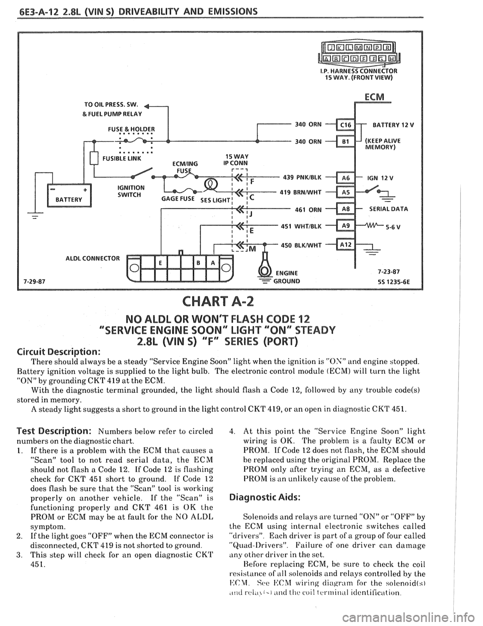
6E3-A-92 2.8b (VIN SI DRIVEABILITY AND EMISSIONS
TO OIL PRESS. SW.
&FUEL PUMP RELAY
FUSE
& HOLDER BATTERY 12
V
.. am.. . FUSIBLE LINK 15 WAY
439
PNWBLK
- 419 BUNNVHT
SERIAL DATA
451
WHTIBLK
450 BLWHT
ALDL CONNECTOR
CHART A-2
NO ALDL OR WONT FLASH CODE 12
""SERVICE ENGlNE SOON" MGHT ""8N13SPEADY
2.8L (VIN S) ""FYSERlES (PORT)
Circuit Description:
There should always be a steady "Service Engine Soon" light when the ignition is "ON" and engine stopped.
Battery ignition voltage is supplied to the light bulb. The electronic control module
(ECM) will turn the light
"ON" by grounding CKT
419 at the ECM.
With the diagnostic terminal grounded, the light should flash
a Code 12, followed by any trouble code(s)
stored in memory.
A steady light suggests a short to ground in the light control CKT 419, or an open in diagnostic CKT 451.
Test Description: Numbers below refer to circled
numbers on the diagnostic chart.
1. If there is a problem with the ECM that causes a
"Scan" tool to not read serial data, the ECM
should not flash a Code 12. If Code 12 is flashing
check for CKT
451 short to ground. If Code 12
does flash be sure that the "Scan" tool is working
properly on another vehicle. If the "Scan" is
functioning properly and CKT 461 is OK the
PROM or ECM may be at fault for the NO
AL,DI,
symptom.
2. If
the light goes "OFF" when the ECM connector is
disconnected, CKT 419 is not shorted to ground.
3. This step will check for an open diagnostic CKrl'
451.
4. At this point the "Service Engine Soon" light
wiring is OK. The problem is a faulty ECM or
PROM. If Code 12 does not flash, the ECM should
he replaced using the original PROM. Replace the
PROM only after trying an ECM, as a defective
PROM is an unlikely cause of the problem.
Diagnostic Aids:
Solenoids and relays are turned "ON" or "OFF" by
the ECM using internal electronic switches called
"drivers". Each driver is part of a group of four called
"Quad-l)rivers". Failure of one driver can damage
any other driver in the set.
Hefore replacing ECM, be sure to check the coil
resistance of
all solenoids and relays controlled by the
14:CM. Set: I':C%f wiring cliugrntn for the solcnoid(s)
.c~~cl rel;~ (-1 ~ititl lllc coil tcrtriitlul itlentilication.