1988 PONTIAC FIERO engine oil
[x] Cancel search: engine oilPage 736 of 1825
DRIVEABILITY AND EMISSIONS 2.8b (VIN 5) 6E3-C2-1
SECTION C2
FUEL CONTROL SYSEEIVI
CONTENTS
GENERAL DESCRIPTION . . . . . . . . . . . . . . . . C2-1 FUEL RAIL SERVICE . . . . . . . . . . . . . , . . . C2-6
PURPOSE ......................... C2-1 UNIT SERVICE PROCEDURES . . . . . . . . . . . C2-6
MODES OF OPERATION . . . . . . . . . . . . . . C2-1 COLD START TUBE & VALVE ASSEMBLY.. . C2-7
Starting Mode . . . . . . . . . . . . . . . . . . . C2-2 FUEL PRESSURE CONNECTION ASSEMBLY . C2-7
Clear Flood Mode . . . . . . . . . . . . . . . . . C2-2 FUEL BLOCK AND SEAL.. . . . . . . . . . . . . . C2-9
Run Mode .. .. . . . . . . . . . . . . . . . . . . C2-2 FUELINJECTORS .. . . . .. ... .... . . . ... C2-9
Acceleration Mode. . . . . . . . . . . . . . . . C2-2 Port Injectors wl Injector Retaining Clips C2-9
Deceleration Mode . . . . . . . . . . . . . . . C2-2 Fuel Pressure Regulator . . . . . . . . . . . . C2-10
Battery Voltage Correction Mode . . . . . C2-2 PORT INJECTORS . . . . . . . . . . . . . . . . . . . C2-10
Fuel Cutoff Mode . . . . . . . . . . . . . . . . . C2-3 PRESSURE REGULATOR.. . . . . . . . . . . . . . C2-10
Fuel Control System Components . . . . . C2-3 COLD START FUEL INJECTION SWITCH . . . C2-1 I
Basic System Operation. . . . . . . . . . . . . C2-3 THROTTLE BODY . . . . . . . . . . . . . . . . . . . C2-11
THROTTLE BODY UNIT . . . . . . . . . . . . . . . C2-3 THROTTLE BODY SERVICE IDENTIFICATION C2-11
FUEL RAIL.. . . . . . . . . . . . . . . . . . . . . . . . C2-3 MINIMUM IDLE SPEED ADJUSTMENT . . . . C2-14
FUEL INJECTOR.. . . . . . . . . . . . . . . . . . . . C2-3 UNIT REPAIR PROCEDURES . . . . . . . . . . . . C2-14
PRESSURE REGULATOR.. . . . . . . . . . . . . . C2-3 IDLE AIR CONTROL VALVE
IDLE AIR CONTROL (IAC) VALVE
. . . . . . . . C2-4 ASSEMBLY &GASKET.. . . . . . . . . . . . . . . C2-14
FUEL PUMP ELECTRICAL CIRCUIT . . . . . . . C2-4 IDLE AIRIVACUUM SIGNAL
DIAGNOSIS . . . . . . . . . . . . . . . . . . . . . . . . . C2-5 HOUSING ASSEMBLY . . . . . . . . . . . . . . . . C2-15
FUEL CONTROL SYSTEM . . . . . . . . . . . . . . C2-5 COOLANT CAVITY COVER & O-RING . . . . * C2-15
IDLE AIR CONTROL VALVE . . . . . . . . . . . . C2-5 IDLE AIR CONTROL / COOLANT
ON-CAR SERVICE . . . . . . . . . . . . . . . . . . . . . C2-5 COVERASSEMBLY .............,.... C2-16
PORT FUEL INJECTION COMPONENTS . . . . C2-5 FUEL PUMP RELAY . . . . . . . . . . . . . . . . . . C2-17
FUEL PRESSURE RELIEF PROCEDURE . . . . . C2-5 OIL PRESSURE SWITCH . . . . . . . . . . . . . . . C2-17
Plenum ........................ C2-5 PARTS INFORMATION . . . . . . . . . . . . . . . . . C2-17
Fuel Rail & Pressure Regulator Assembly . C2-5
GENERAL DESCRIPTION
PURPOSE
The basic function of the fuel control system is to
control fuel delivery to the engine.
Fuel is delivered to the engine by individual fuel
injectors mounted in the intake manifold near each
cylinder. The main control sensor is the oxygen
(02) sensor,
which is located in the exhaust manifold. The
O2
sensor tells the ECM how much oxygen is in the
exhaust gas, and the ECM changes the airlfuel ratio to
the engine by controlling the fuel injectors. The best
mixture to minimize exhaust emissions is
14.7 to 1,
which allows the catalytic converter to operate the
most efficiently. Because of the constant measuring
and adjusting of the airlfuel ratio, the fuel injection
system is called
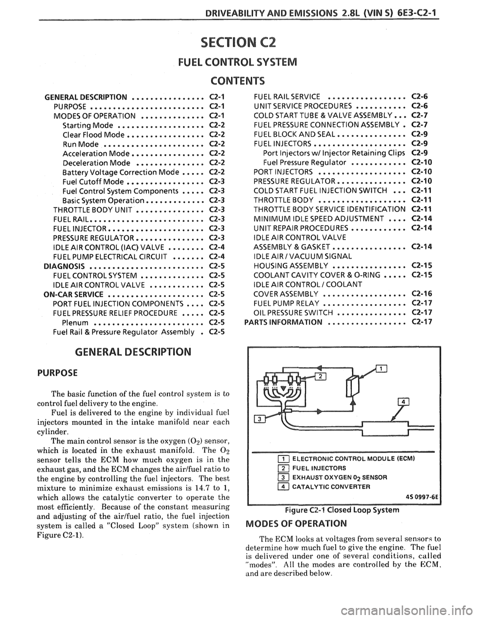
a "Closed LoopJ' system (shown in
Figure C2-1).
ELECTRONIC CONTROL MODULE (ECM)
FUEL INJECTORS
EXHAUST OXYGEN
02 SENSOR
1 CATALYTIC CONVERTER
45 0997-6E
Figure C2-1 Closed Loop System
MODES OF OPERATION
The ECM looks at voltages from several sensors to
determine how much fuel to give the engine.
The fuel
is delivered under one of several conditions,
called
"modes". All the modes are controlled by the E:CM.
and are described below.
Page 738 of 1825
DRIVEABILITY AND EMISSIONS 2.8L (VIN 5) 6E3-CZ-3
Fuel Cutofl Mode
No fuel is delivered by the injector when the
ignition is "OFF". This prevents dieseling. Also, fuel
is not delivered if no reference pulses are seen from
the distributor, which means the engine is not
running. This prevents flooding.
Fares Control System Components
The fuel control system is made up of the following
parts:
e Fuel Injectors
@ Throttle Body
e Fuel pump relay
@ Fuel Pressure Regulator
@ Fuel Rail
Basic System Operation
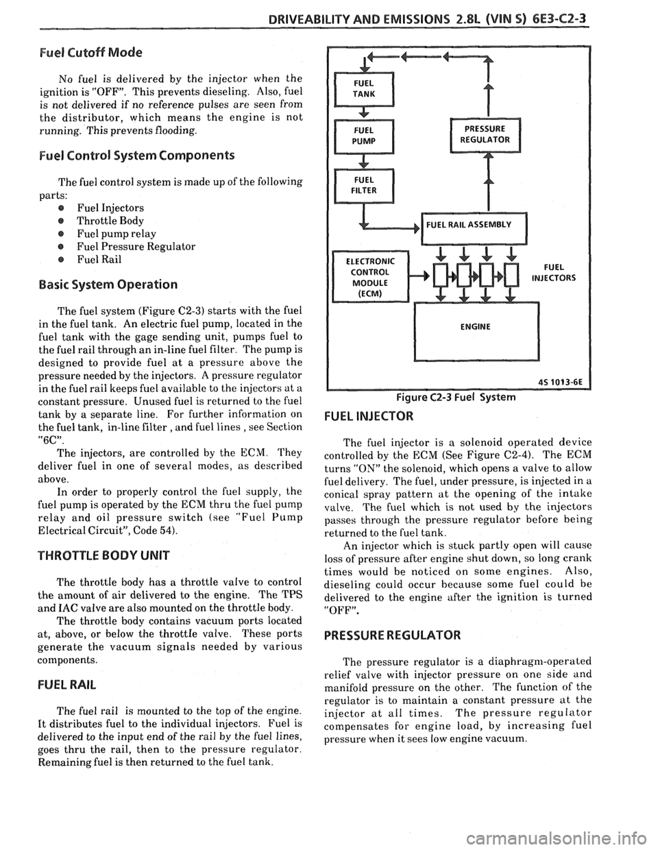
The fuel system (Figure C2-3) starts with the fuel
in the fuel tank. An electric fuel pump, located in the
fuel tank with the gage sending unit, pumps fuel to
the fuel rail through an in-line fuel filter. The pump is
designed to provide fuel at a pressure above the
pressure needed by the injectors. A pressure regulator
in the fuel rail keeps fuel available to the injectors at a
constant pressure. Unused fuel is returned to the fuel
tank by a separate line. For further information on
the fuel tank, in-line filter
, and fuel lines , see Section
"6C".
The injectors, are controlled by the ECM. They
deliver fuel in one of several modes, as described
above. In order to properly control the fuel supply, the
fuel pump is operated by the ECM thru the fuel pump
relay and oil pressure switch (see
"Fuel Pump
Electrical Circuit", Code 54).
THROTTLE BODY UNIT
The throttle body has a throttle valve to control
the amount of air delivered to the engine. The TPS
and
IAC valve are also mounted on the throttle body.
The throttle body contains vacuum ports located
at, above, or below the
throttIe valve. These ports
generate the vacuum signals needed by various
components.
FUEL RAIL
The fuel rail is mounted to the top of the engine.
It distributes fuel to the individual injectors. Fuel is
delivered to the input end of the rail by the fuel lines,
goes thru the rail, then to the pressure regulator.
Remaining fuel is then returned to the fuel tank.
Figure C2-3 Fuel System
FUEL INJECTOR
The fuel injector is a solenoid operated device
controlled by the ECM (See Figure C2-4). The ECM
turns
"ON" the solenoid, which opens a valve to allow
fuel delivery. The fuel, under pressure, is injected in a
conical spray pattern at the opening of the intake
valve. The fuel which is not used by the injectors
passes through the pressure regulator before being
returned to the fuel tank.
An injector which is stuck partly open will cause
loss of pressure after engine shut down, so long crank
times would be noticed on some engines. Also,
dieseling could occur because some fuel could be
delivered to the engine after the ignition is turned
"OFF".
PRESSURE REGULATOR
The pressure regulator is a diaphragm-operated
relief valve with injector pressure on one side and
manifold pressure on the other. The function of the
regulator is to maintain a constant pressure at the
injector at all times. The pressure regulator
compensates for engine load, by increasing fuel
pressure when it sees low engine vacuum.
Page 740 of 1825
DRIVEABILITY AND EMISSIONS 2.8L (VIN 5) 6E3-C2-5
As a backup system to the fuel pump relay, the
fuel pump can also be turned "ON" by the oil pressure
switch. The oil pressure switch is a normally open
switch which closes when oil pressure reaches about
28
kPa (4 psi). If the fuel pump relay fails, the oil
pressure switch will close and run the fuel pump.
An inoperative fuel pump relay can result in long
cranking times, particularly if the engine is cold.
An inoperative fuel pump would cause a no start
condition. A fuel pump which does not provide enough
pressure can result in poor performance.
FUEL CONTROL SYSTEM
Some failures of this system will result in an
"Engine Cranks But Won't Run". If
this condition
exists, see CHART A-3. This chart will determine if
the problem is caused by the ignition system, ECM or
fuel pump circuit. If
it's determined to be a fuel
problem, CHART
A-7 will be used. This includes the
injectors, pressure regulator, fuel pump and fuel pump
relay. The fuel system wiring schematic is covered on
the facing page of Code CHART
54.
If a malfunction occurs in the fuel control system
it usually results in either a rich or a lean exhaust
condition. This condition is sensed by the oxygen
sensor and the ECM will change the fuel calculation
(injector pulse width) based on the
02 sensor reading.
The change made to the fuel calculation will be
indicated by a change in the block learn values which
can be monitored by a "Scan" tool. The normal block
learn values are around 128 and if the
O2 sensor is
sensing a lean condition, the ECM will add fuel and
this will result in a block learn value above 128. If the
02 sensor is sensing a rich exhaust the ECM will
reduce fuel to the engine and this will result in block
learn values below 128. Some variations in block
learn values are normal because all engines are not
exactly the same. However, if the block learn values
are
+ 10 counts from 128, a system problem exists. If
the block learn values are greater than 138, see Code
44 for items which can cause a lean system.
If the block learn values are less than 118, see
Code
45 for items which can cause the system to run
rich. If a driveability symptom exists, refer to the
particular symptom in Section
"B" for additional
items to check.
IDLE AIR CONTROL VALVE
A "Scan" tool will read IAC position in steps
(counts).
"0" steps indicates the ECM is commanding
the IAC to be driven all the way in, to a fully seated
position, and this is usually caused by a vacuum leak.
The higher the number of counts the more air being
allowed to pass the IAC valve. CHART C-2C can be
used to diagnosis the IAC valve. Also refer to "Rough, Unstable,
or Incorrect Idle, Stalling" in "Symptoms,"
Section
"B" for other possibilities for the cause of idle
problems.
ON-CAR SERVICE
PORT FUEL INJECTION COMPONENTS
CAUTION:
Before servicing an injector, fuel
rail, or pressure regulator, it is
necessary to relieve the pressure in
the fuel system, to minimize the risk
of fire and personal injury. (See
"Fuel Pressure Relief Procedure"
below). To reduce the chance of
personal injury, cover the fuel line
with a shop cloth to collect the fuel,
and then place the cloth in an
approved container.
FUEL PRESSURE RELIEF PROCEDURE
Connect fuel gage J 34730-1 or equivalent to fuel
pressure valve. Wrap a shop towel around fitting
while connecting gage to avoid spillage.
Install bleed hose into an approved container and
open valve to bleed system pressure.
Plenum
Remove or Disconnect
1. Negative battery cable.
2. Air
inlet duct at throttle body.
3. Throttle body retaining bolts
(2).
4. EGR pipe bolts (2).
5. Throttle cable bracket.
6. Plenum bolts (8).
Install or Connect
I. Plenum and gaskets.
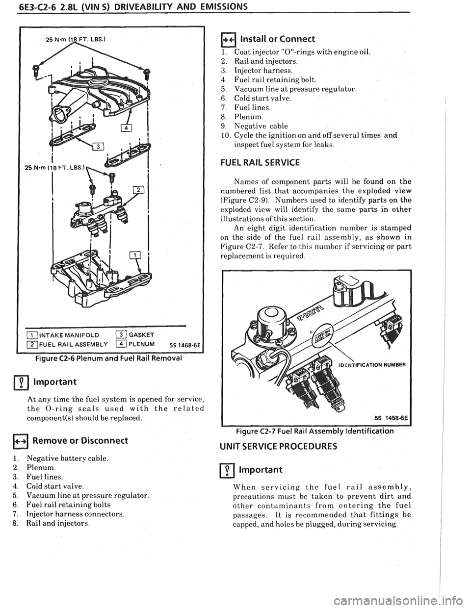
2. Plenum bolts. See Figure C2-6.
3. Throttle cable bracket.
4. EGR pipe bolts.
5. Throttle body and bolts.
6. Air inlet duct
7. Negative battery cable.
Fuel Rail and Pressure Regulator Assembly
Important
When servicing the fuel rail assembly,
precautions must be taken to prevent dirt and
other contaminants from entering the fuel
passages. It is recommended that fittings
he
capped and holes be plugged during servicing.
Page 741 of 1825
6E3-C2-6 2.8L (VIN 5) DRIVEABILITY AND EMISSIONS
FUEL RAIL ASSEMBLY
Figure C2-6 Plenum and Fuel Rail Removal
Important
At any time the fuel system is opened for service,
the O-ring seals used with the related
component(s) should be replaced.
Remove or Disconnect
1. Negative battery cable.
2. Plenum.
3. Fuel lines.
4. Cold start valve.
5. Vacuum line at pressure regulator.
6. Fuel rail retaining bolts
7. Injector harness connectors.
8. Rail and injectors.
install or Connect
1. Coat injector "On-rings with engine oil.
2. Rail and injectors.
3. Injector harness.
4. Fuel rail retaining bolt.
5. Vacuum line at pressure regulator.
6. Cold start valve.
7. Fuel lines.
8. Plenum.
9. Negative cable
10. Cycle the ignition on and off several times and
inspect fuel system for leaks.
FUEL RAIL SERVICE
Names of component parts will be found on the
numbered list that accompanies the exploded view
(Figure C2-9). Numbers used to identify parts on the
exploded view will identify the same parts in other
illustrations of this section.
An eight digit identification number is stamped
on the side of the fuel rail assembly, as shown in
Figure C2-7. Refer to this number if servicing or part
replacement is required.
Figure C2-7 Fuel Rail Assembly [dentification
UNIT SERVICE PROCEDURES
Important
When servicing the fuel rail assembly,
precautions must be taken to prevent dirt and
other contaminants from entering the fuel
passages. It is recommended that fittings be
capped, and holes be plugged, during servicing.
Page 745 of 1825
![PONTIAC FIERO 1988 Service Repair Manual
6E3-C2-10 2.8L (VIN 5) DRIVEABILITY AND EMISSIONS
Inspect
@ All injector O-ring seals (86).
- Replace if damaged.
+++ Assemble [7]
e New O-ring seals (86) as required, on port
i~,jectors PONTIAC FIERO 1988 Service Repair Manual
6E3-C2-10 2.8L (VIN 5) DRIVEABILITY AND EMISSIONS
Inspect
@ All injector O-ring seals (86).
- Replace if damaged.
+++ Assemble [7]
e New O-ring seals (86) as required, on port
i~,jectors](/manual-img/50/57415/w960_57415-744.png)
6E3-C2-10 2.8L (VIN 5) DRIVEABILITY AND EMISSIONS
Inspect
@ All injector O-ring seals (86).
- Replace if damaged.
+++ Assemble [7]
e New O-ring seals (86) as required, on port
i~,jectors (85).
lnstall or Connect
1. Lubricate all injector O-ring seals with engine oil.
2. Port injectors to fuel rail and pressure regulator
assembly
(11).
3. Rotate injector retainer clips (87) to locking
position (Figure C2-12).
Fuel Pressure Regulator
Important
The pressure regulator is factory adjusted and is
not serviceable. Do not attempt to remove the
regulator from the fuel rail.
PORT INJECTORS
Each port injector is located and held in position
by
a retainer clip that must be rotated to release
and/or lock the injector in place, as shown in Figure
C2-13.
FUEL RAIL
85 INJECTOR - PORT
87 CLIP-INJECTOR RETAINER
Figure C2-13 Port lnjector with Injector Retainer Clip
Remove or Disconnect
1. Rotate injector retaining clip(s) (87) to unlocked
position.
2. Injectors
(85).
inspect
@ All injector O-ring seals (86).
- Replace if damaged.
Assemble
@ New O-ring seals (86) as required, on injectors
(85).
Install or Connect
1. Lubricate all injector O-ring seals with engine oil.
2. Injectors
t,o fuel rail and pressure regulator
assembly
(1 1).
3. IZotate injector retainer clips (87) to locking
position (Figure
C2-13).
240PWESSUREREGULATORAND
BASE ASSEMBLY
Figure C2-14 Fuel Pressure Regulator
PRESSURE REGULATOR
Figure
C2-14
important
The pressure regulator is factory adjusted and is
not serviceable.
DO not attempt to remove
regulator cover.
a Remove or Disconnect
1. Front crossover tube rc1;ainer attaching screw
assembly
(235) anri c~-~):,so irer tube retainer (234j.
2. Retainer to base screlv sssembly !273) and re:i!:
crossover tube ret,ai nclr I2701
3. Separate the left hand fuel rail and plug assembly
(200) from the rigl~f, hand fuel rail and tube
assembly
(220).
4. Bracket to rail attaching screw assembly (2561,
bracket to hase attaching screw assembly (258)
and the pressure regulator and base assembly
bracket
(255).
5. Rear hracket attaching study assembly (222).
6. Base to right hancl rail screw assembly (275).
Page 746 of 1825
DRIVEABILITY AND EMISSIONS 2.8L (VIN 5) 6E3-CZ-1 l
7. Pressure
regulator and base assembly (240) from
right hand rail assembly (220).
8. Rotate the regulator and base assembly to remove
from the fuel outlet tube.
9. Base to rail connector (250).
Important
When removing 0-Ring seals, note locations and
sizes, to assure correct replacement and re-
assembly.
10. 0-Ring seals:
@ Connector (252).
@ Fuel outlet tube (224).
@ Rear crossover tube (267).
@ Front crossover tube (232).
Install or Connect
1. Lubricate with engine oil, and install 0-Ring
seals:
@ Connector (252).
@ Fuel outlet tube (224).
@ Rear crossover tube (267).
@ Front crossover tube (232).
2. Base
to rail connector (250) in pressure regulator
and base assembly
(240).
3. Regulator and base assembly on fuel outlet tube.
4. Rotate the regulator and base assembly to install
base to rail connector (250) into right hand rail
assembly.
5. Base
to right hand rail screw assembly
(275).
6. Pressure
regulator and base assembly bracket
(255), bracket to base attaching screw assembly
(258) and bracket to rail attaching screw assembly
(256).
7. Rear bracket attaching study assembly (222).
8. Left hand rail and plug assembly (200), with front
and rear crossover tubes (230) and
265), to right
hand rail and tube assembly (220).
9. Rear crossover tube retainer (270) and retainer to
base screw assembly (273).
10. Front crossover tube retainer
(234) and retainer
attaching screw assembly
(235).
COLD START FUEL INJECTION SWITCH
Remove or Disconned
1. Connector.
2. Switch.
n Install or Connect
1. Switch.
2. Connector.
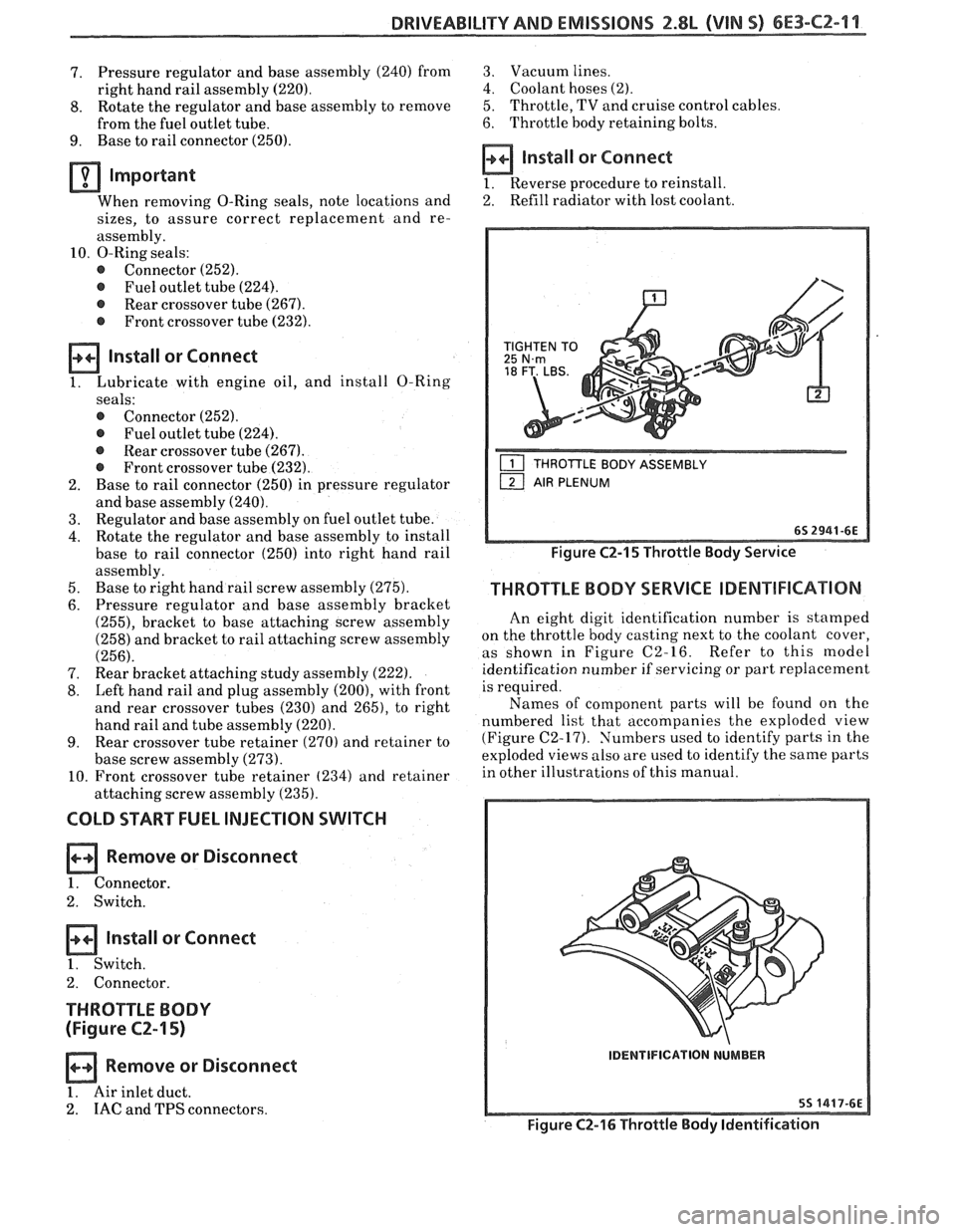
THROTTLE BODY
(Figure
C2-15)
Remove or Disconnect
1. Air inlet duct.
2.
IAC and TPS connectors.
3. Vacuum lines.
4. Coolant hoses (2).
5. Throttle, TV and cruise control cables
6. Throttle body retaining bolts.
Install or Connect
1. Reverse procedure to reinstall.
2. Refill
radiator with lost coolant.
THROTTLE BODY ASSEMBLY
Figure C2-15 Throttle Body Service
THROTTLE BODY SERVICE IDENTIFICATION
An eight digit identification number is stamped
on the throttle body casting next to the coolant cover,
as shown in Figure C2-16. Refer to this model
identification number if servicing or part replacement
is required.
Names of component parts will be found on the
numbered list that accompanies the exploded view
(Figure C2-17). Numbers used to identify parts in the
exploded views also are used to identify the same parts
in other illustrations of this manual.
IDENTIFICATION NUMBER
Figure C2-16 Throttle Body Identification
Page 752 of 1825
DRIVEABILITY AND EMISSIONS 2.8L (VIN 5) 6E3-C2-17
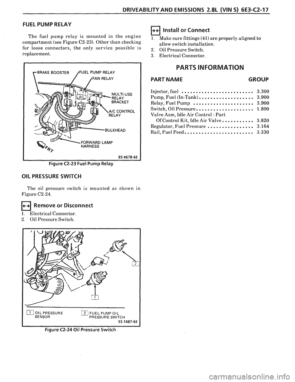
FUEL PUMP RELAY
The fuel pump relay is mounted in the engine
compartment (see Figure C2-23). Other than checking
for loose connectors, the only service possible is
replacement.
rBRAKE BOOSTER /FUEL PUMP RELAY
/ /FAN RELAY
RELAY
Y '"ccONT"L
BULKHEAD
FORWARD
LAMP HARNESS
Figure C2-23 Fuel Pump Relay
OIL PRESSURE SWITCH
The oil pressure switch is mounted as shown in
Figure C2-24.
Remove or Disconnect
1. Electrical Connector.
2. Oil Pressure Switch.
Install or Connect
1. Make sure fittings (41) are properly aligned to
allow switch installation.
2. Oil Pressure Switch.
3. Electrical Connector.
PARTS INFORMATION
PART NAME GROUP
Injector, fuel ......................... 3.300
Pump, Fuel (In-Tank)
................... 3.900
Relay, Fuel Pump
..................... 3.900
Switch, Oil Pressure.
................... 1.800
Valve Asm, Idle Air Control
: Part
Of Control Kit, Idle Air Valve.
.......... 3.820
Regulator, Fuel Pressure
................ 3.164
Rail, Fuel Feed. ....................... 3.330
PRESSURE SWI
Figure C2-24 Oil Pressure Switch
Page 753 of 1825
6E3-C2-18 2.8L (VIN S) DRIVEABILITY AND EMISSIONS
CHART C-2A
INJECTOR BALANCE TEST
The injector balance tester is a tool used to turn the injector on for a precise
amount of time, thus spraying a measured amount of fuel into the manifold.
This causes a drop in fuel rail pressure that we can record and compare between
each injector. All injectors should have the same amount of pressure drop
( k 10
kpa). Any injector with a pressure drop that is 10 kpa (or more) greater or less
than the average drop of the other injectors should be considered faulty and
replaced.
Engine "cool down" period
(10 minutes) is necessary to avoid irregular
readings due to "Hot Soak" fuel boiling. With ignition
"OFF" connect fuel gauge
5347301 or equivalent to fuel pressure tap. Wrap a shop towel around fitting
while connecting gage to avoid fuel spillage.
Disconnect harness connectors at all injectors, and connect injector tester
J-
34730-3, or equivalent, to one injector. On Turbo equipped engines, use adaptor
harness furnished with injector tester to energize injectors that are not
accessible. Follow manufacturers instructions for use of adaptor harness.
Ignition must be
"OFF" at least 10 seconds to complete ECM shutdown cycle.
Fuel pump should run about
2 seconds after ignition is turned "ON". At this
point, insert clear tubing attached to vent valve into a suitable container and
bleed air from gauge and hose to insure accurate gauge operation. Repeat this
step until all air is bled from gauge.
STEP 2
Turn ignition "OFF" for 10 seconds and then "ON" again to get fuel pressure
to its maximum. Record this initial pressure reading. Energize tester one time
and note pressure drop at its lowest point (Disregard any slight pressure
increase after drop hits low point.). By subtracting this second pressure reading
from the initial pressure, we have the actual amount of injector pressure drop.
STEP 3
Repeat step 2 on each injector and compare the amount of drop. Usually, good
injectors will have virtually the same drop. Retest any injector that has
a
pressure difference of lOkPa, either more or less than the average of the other
injectors on the engine. Replace any injector that also fails the retest. If the
pressure drop of all injectors is within
lOkPa of this average, the injectors
appear to be flowing properly. Reconnect
them and review "Symptoms," Section
"B".
NOTE: The entire test should not be repeated more than once without
running the engine to prevent flooding. (This includes any retest on
fa ulty injectors).