1988 PONTIAC FIERO engine oil
[x] Cancel search: engine oilPage 898 of 1825
DRIVEABILITY AND EMISSIONS 5.OL (VIN F) & 5.7L (VIN 8) 6E3-C2-11
3. Separate left hand fuel rail and plug assembly
(200) from right hand fuel rail and plug assembly
(220).
4. Bracket-to-rail
attaching screw assembly (256),
two bracket-to-base attaching screw assemblies
(258) and pressure regulator and base assembly
bracket
(255).
5. Screw
assembly (235), which attaches fuel outlet
tube to right hand rail (220).
6. Base to right hand rail screw assembly (275).
7. Pressure regulator and base assembly (240) from
right hand rail assembly (220).
8. Rotate regulator and base assembly to remove
from fuel outlet tube.
9. Base to rail connector (250).
10. O-ring seals and discard:
@ Connector (252).
@ Fuel outlet tube (224).
@ Rear crossover tube (267).
@ Front crossover tube (232).
Important
When removing O-ring seals, note locations and
sizes, to assure correct replacement and re-
assembly.
Inspect
@ O-rings and sealing surfaces, for damage that
could prevent proper sealing.
- Replace any damaged O-ring seals.
n Install or Connect
1. Lubricate with engine oil, and install O-ring seals:
@ Connector (252).
@ Fuel outlet tube (224).
@ Rear crossover tube (267).
@ Front crossover tube (232).
Base-to-rail connector (250) in pressure regulator
and base assembly (240).
Regulator and base assembly on fuel outlet tube.
Rotate the regulator and base assembly to install
base to rail connector
(250) into right hand rail
assembly
(220).
Base to right hand rail screw assembly (275).
Pressure regulator and base assembly bracket
(2551, two brackets to base attaching screw
assembly (258) and bracket to rail attaching screw
assembly (256).
Rear bracket attaching screw assembly
(235).
Left hand rail and plug assembly (2001, with front
and rear crossover tubes (230) and
265), to right
hand rail and tube assembly
(220).
Rear crossover tube retainer (270) and retainer to
base screw assembly
(273).
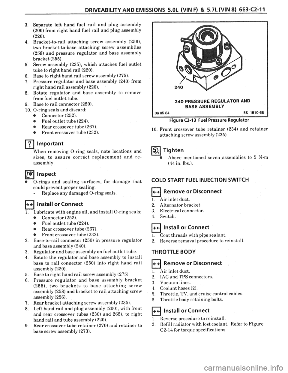
240PRESSUREREGUbATORAND
BASE ASSEMBLY
Figure C2-13 Fuel Pressure Regulator
10. Front crossover tube retainer (234) and retainer
attaching screw assembly
(235).
Tighten
@ Above mentioned seven assemblies to 5 N-m
(44 in. lbs.).
COLD START FUEL INJECTION SWITCH
Remove or Disconnect
1. Air inlet duct.
2. Alternator bracket.
3. Electrical connector
4. Switch.
Install or Connect
1. Coat threads with pipe sealant.
2. Reverse
removal procedure to reinstall.
THROTTLE BODY
Remove or Disconnect
I. Air inlet duct.
2. IAC and 'I'PS connectors.
3. Vacuum lines.
4. Coolant hoses (2).
5. 'I'hrottle, 'L'V, and cruise control cables.
6. Throttle body retaining bolts.
a Install or Connect
1, Reverse procedure to reinstall.
2. Refill
radiator with lost coolant. Refer to Figure
C2-14 for torque specifications.
Page 903 of 1825
6E3-CZ-16 5.OL (VIN F) & 5.7L(VIN 8) DRIVEABILITY AND EMISSIONS
Tighten
- @ Screw assemblies to 3.0 Nem (27.0 in. lbs.).
4. IAC valve assembly (70). (See "Idle Air Control
Valve and Gasket" instructions).
NOTICE: Before installing the IAC valve assembly,
the position of its pintle
MUST be checked.
If pintle is extended too far, damage to the
assembly may occur. (See
"Idle Air
Control Valve and Gasket" instructions.)
FUEL PUMP RELAY
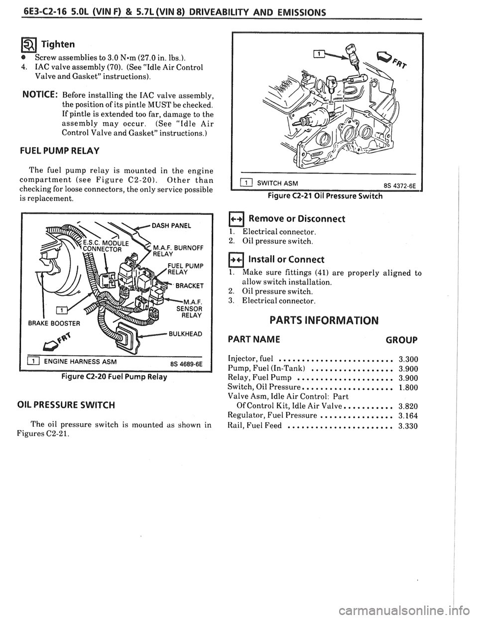
The fuel pump relay is mounted in the engine
compartment (see Figure
C2-20). Other than
checking for loose connectors, the only service possible
is replacement.
BRAKE BOOSTER
Figure C2-20 Fuel Pump Relay
OIL PRESSURE SWITCH
The oil pressure switch is mounted as shown in
Figures C2-2
1.
Figure C2-21 Oil Pressure Switch
a Remove or Disconnect
I. Electrical connector.
2. Oil pressure switch.
Install or Connect
1. Make sure fittings (41) are properly aligned to
allow switch installation.
2. Oil pressure switch.
3. Electrical connector.
PARTS INFORMATION
PART NAME GROUP
Injector, fuel ......................... 3.300
Pump, Fuel (In-Tank)
.................. 3.900
Relay, Fuel Pump
..................... 3.900
Switch, Oil Pressure,
................... 1.800
Valve Asm, Idle Air Control: Part
Of Control Kit, Idle Air Valve. .......... 3.820
Regulator, Fuel Pressure
................ 3.164
Itail, Fuel Feed ....................... 3.330
Page 905 of 1825
6E3-CZ-18 5.OL (VIN F) & 5.7L(VIN 8) DRIVEABILITY AND EMISSIONS
CHART C-2A
INJECWR BALANCE TEST
The injector balance tester is a tool used to turn the injector on for a precise
amount of time, thus spraying
a measured amount of fuel into the manifold.
This causes a drop in fuel rail pressure that we can record and compare between
each injector. All injectors should have the same amount of pressure drop
( f 10
kPa). Any injector with a pressure drop that is 10 kPa (or more) greater or less
than the average drop of the other injectors should be considered faulty and
replaced.
STEP 1
Engine "cool down" period (10 minutes) is necessary to avoid irregular
readings due to "Hot Soak" fuel boiling. With ignition "OFF" connect fuel gauge
5347301 or equivalent to fuel pressure tap. Wrap a shop towel around fitting
while connecting gage to avoid fuel spillage.
Disconnect harness connectors at all injectors, and connect injector tester
J-
34730-3, or equivalent, to one injector. On turbo equipped engines, use adaptor
harness furnished with injector tester to energize injectors that are not
accessible. Follow manufacturers instructions for use of adaptor harness.
Ignition must be "OFF" at least 10 seconds to complete
ECM shutdown cycle.
Fuel pump should run about
2 seconds after ignition is turned "ON". At this
point, insert clear tubing attached to vent valve into a suitable container and
bleed air from gauge and hose to insure accurate gauge operation. Repeat this
step until all air is bled from gauge.
Turn ignition
"OFF" for 10 seconds and then "ON" again to get fuel pressure
to its maximum. Record this initial pressure reading. Energize tester one time
and note pressure drop at its lowest point (Disregard any slight pressure
increase after drop hits low point.). By subtracting this second pressure reading
from the initial pressure, we have
the actual amount of injector pressure drop.
STEP 3
Rcpcat stcp 2 on each injector and compare the amount of drop. Usually, good
injectors will have virtually the same drop. Retest any injector that has a
pressure difference of
LOkPa, either more or less than the average of the other
injectors on the engine. Replace any injector that also fails the retest.
If the
pressure drop of all injectors is within
lOkPa of this average, the injectors
appear to be flowing properly. Reconnect them and review symptoms, section
"B".
NOTE: The entire test should not be repeated more than once without
running the engine to prevent flooding. (This includes any retest on
faulty injectors).
Page 907 of 1825
6E3-C2-20 5.0L (VIN F) & 5.7L (WIN 8) DRIVEABILITY AND EMISSIONS
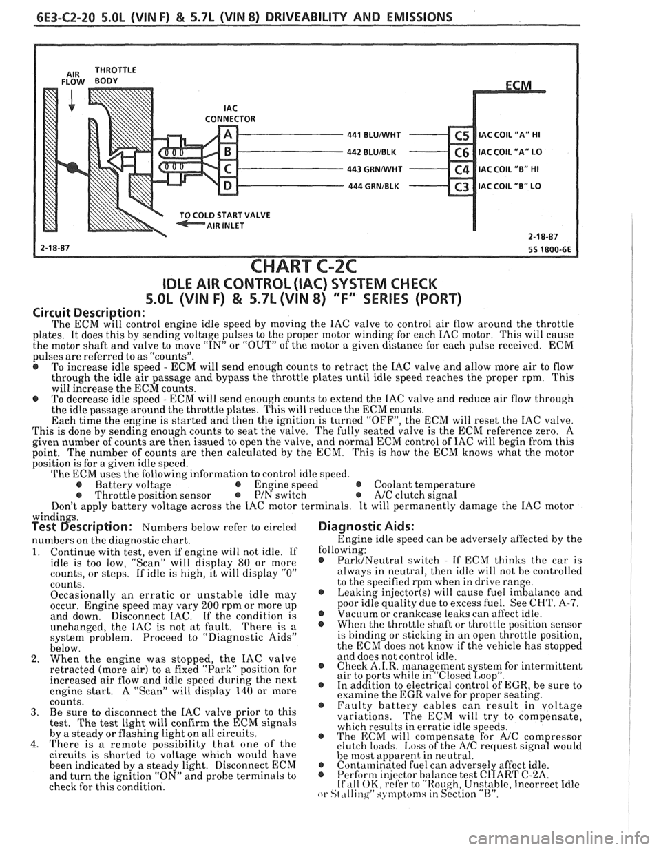
CONNECTOR - 441 BLUMlHT C5 IAC C0lL1'A" HI - 442 BLUIBLK C6 IAC COIL "A" LO - 443 GRNMlHT C4 IAC COIL "B" HI - 444 GRNIBLK C3 lAC COIL "B" LO v
START VALVE
CHART C-2C
IDLE AIR CONTROL (IAC) SYSTEM CHECK
S.OL (VIN F) & 5.7L (VIN 8) "F'" SERIES (PORT)
Circuit Description:
The ECM will control engine idle speed by moving the IAC valve to control air flow around the throttle
plates. It does this by sending voltage pulses to the proper motor winding for each IAC motor. This will cause
the motor shaft and valve to move
"IN" or "OUT" of the motor a given distance for each pulse received. ECM
pulses are referred to as "counts".
@ To increase idle speed - ECM will send enough counts to retract the IAC valve and allow more air to flow
through the idle air passage and bypass the throttle plates until idle speed reaches the proper rpm. This
will increase the ECM counts.
e To decrease idle speed - ECM will send enough counts to extend the IAC valve and reduce air flow through
the idle passage around the throttle plates. This will reduce the ECM counts.
Each time the engine is started and then the ignition is turned "OFF", the ECM will reset the IAC valve.
This is done by sending enough counts to seat the valve.
The fully seated valve is the ECM reference zero. A
given number of counts are then issued to open the valve, and normal ECM control of IAC will begin from this
point. The
number of counts are then calculated by the ECM. This is how the ECM knows what the motor
position is for a given idle speed.
The ECM uses the following information to control idle speed.
@ Battery voltage @ Engine speed @ Coolant temperature @ Throttle position sensor @ PIN switch e A/C clutch signal
Don't apply battery voltage across the IAC motor terminals. It will permanently damage the IAC motor
windin s. Test 6escription: Numbers below refer to circled
numbers on the diagnostic chart.
1. Continue with test, even if engine will not idle. If
idle is too low, "Scan" will display 80 or more
counts, or steps. If idle is high, it will display
"0"
counts.
Occasionally an erratic or unstable idle
[nay occur. Engine speed may vary 200 rpm or more up
and down. Disconnect IAC. If the condition is
unchanged, the IAC is not at fault.
There is a
system problem. Proceed to "Diagnostic Aids"
below.
2. When the engine was stopped, the IAC valve
retracted (more air) to
a fixed "Park" position for
increased air flow and idle speed during the next
engine start. A "Scan" will display 140 or more
coiints. 3. Be sure to disconnect the IAC valve prior to this
test.
The test light will confirm the ECM signals
by a steady or flashing light on all circuits.
4. There is a remote possibility that one of the
circuits is shorted to voltage which would have
been indicated by a steady light. Disconnect ECM
and turn the ignition "ON" and probe terminals to
check for this condition.
Diagnostic Aids:
Engine idle speed can be adversely affected by the
following:
@ ParMNeutral switch - If ECM thinks the car is
always in neutral, then idle will not be controlled
to the specified rpm when in drive range.
@ Leaking injector(s) will cause fuel imbalance and
poor idle quality due to excess fuel. See CHT.
A-7. @ Vacuum or crankcase leaks can affect idle. @ Whenthethrottleshaftorthrottlepositionsensor
is binding or sticking in an open throttle position,
the ECM does not know if the vehicle has stopped
and does not control idle.
@ Check A.I.R. management s stem for intermittent
air to orts while in "~losed~oo~". @ In ad&tion to electrical control of EGR, be sure to
examine the EGR valve for proper seating.
@ Faulty battery cables can result in voltage
variations. The ECM will try to compensate,
which results in erratic idle speeds.
@ 'I'he ECM will com ensate for A/C com ressor
clutch loacls. [.ass ofthe NC request sign8 would
he 11lost apparent, in neutral. @ Contalninatecl fuel can adverse1 affect idle. @ Perform i~!jector balance test C~ART C-2A. If ,111 OK, refer to "Rough, Unstable, Incorrect Idle or St ,tllinqW SJ tnptcfinsiin S~'ction "11''.
Page 917 of 1825
6E3-C4-2 5.OL (VIN F) & 5.7L (VIN 8) DRIVEABILITY AND EMISSIONS
The "Reference" signal also triggers the fuel
injection system. Without the "Reference" signal the
engine cannot run. This signal can be checked by
using
a "Scan" tool which will help determine the
cause of an engine that cranks but won't start.
OM-CAR SERVICE
SETTING TIMING
The initial base timing is set by disconnecting the
timing connector. Then set the timing to the
specification shown on emmision control information
label. This will cause Code 42 to be stored in the
memory of the ECM. The memory must be cleared
after setting timing.
How Code 42 Is Determined
When the system is running on the HE1 module,
that is, no voltage on the bypass line, the
HE1 module
grounds the EST signal. The ECM expects to see no
voltage on the EST line during this condition.
If it
sees a voltage, it sets code 42 and will not go into the
EST mode.
When the rpm for EST is reached, (about
400
rpm), the ECM applies 5 volts to the bypass line and
the EST should no longer be grounded in the
HE1
module, so the EST voltage should be varying.
If the bypass line is open or grounded, the
HE1
module will not switch to EST mode, so the EST
voltage will be low and Code 42 will be set.
PARTS INFORMATION
PART NAME GROUP
Coil, Distr ........................... 2.170
Controller, ECM
(Remanufactured)
................ 3.670
Distributor
.......................... 2.361
Module, Distr
........................ 2.383
Page 919 of 1825
6E3-C4-4 5.OL (VIN F) & 5.7L (VIN 8) DRIVEABILITY AND EMISSIONS
"C" /
DISTRIBUTOR CONNECTOR
CONNECTOR
430 PPLNVHT
424 TANIBLK
- - - GRY. CONN.
2-F3-87
7-27-87
SS 1356-6E
CHART C-4
IGNITION SYSTEM CHECK
(INTEGRAL COIL)
5.0b (VIN F) & 5.7L (VIN 8) "F" SERIES (PORT)
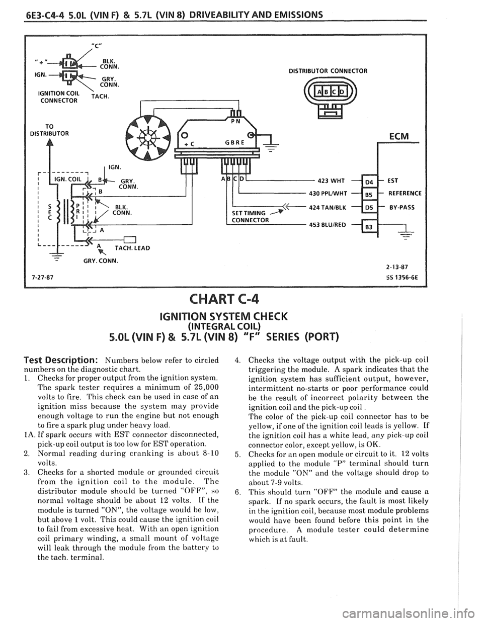
Test Description: Numbers below refer to circled
numbers on the diagnostic chart.
1. Checks for proper output from the ignition system.
The spark tester requires a minimum of 25,000
volts to fire. This check can be used in case of an
ignition miss because the system may provide
enough voltage to run the engine but not enough
to fire a spark plug under heavy load.
IA. If spark occurs with EST connector disconnected,
pick-up coil output is too low for
EST operation.
2. Normal reading during cranking is about
8-10
volts.
3. Checks for a shorted module or grounded circuit
from the ignition coil to the module. The
distributor module should be turned
"OFF", so
normal voltage should be about 12 volts. If the
module is turned
"ON", the voltage would be low,
but above
1 volt. This could cause the ignition coil
to fail from excessive heat. With an open ignition
coil primary winding,
a small mount of voltage
will leak through the module from the battery to
the tach. terminal.
4. Checks the voltage output with the pick-up coil
triggering the module.
A spark indicates that the
ignition system has sufficient output, however,
intermittent no-starts or poor performance could
be the result of incorrect polarity between the
ignition coil and the pick-up coil
.
The color of the pick-up coil connector has to be
yellow, if one of the ignition coil leads is yellow. If
the ignition coil has a white lead, any pick-up coil
connector color, except yellow, is
OK.
5. Checks
for an open module or circuit to it. 12 volts
applied to the module
"P" terminal should turn
the module
"ON" and the voltage should drop to
about
7-9 volts.
6. This should turn "OFF" the module and cause a
spark. If no spark occurs, the fault is most likely
in the ignition coil, because most module problems
would have been found before this point in the
procedure.
A module tester could determine
which is at fault.
Page 929 of 1825
6E3-C6-2 5.OL (VIN F) & 5.7L (VIN 8) DRIVEABILITY AND EMISSIONS
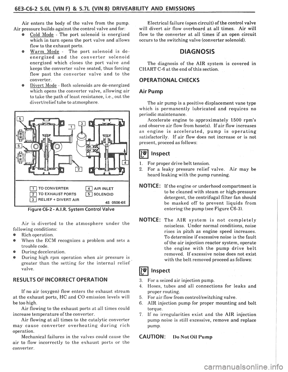
Air enters the body of the valve from the pump.
Air pressure builds against the control valve and for:
@ Cold Mode - The port solenoid is energized
which in turn opens the port valve and allows
flow to the exhaust ports.
Warm Mode
- The port solenoid is de-
energized and the converter solenoid
energized which closes the port valve and
keeps the converter valve seated, thus forcing
flow past the converter valve and to the
converter.
@ Divert Mode - Both solenoids are de-energized
which opens the converter valve, allowing air
to take the path of least resistance,
i.e., out the
divertlrelief tube to atmosphere. Electrical
failure (open circuit) of the control valve
will divert air flow overboard at all times. Air will
flow to the converter at all times if an open circuit
occurs to the switching valve (converter solenoid).
DIAGNOSIS
The diagnosis of the AIR system is covered in
CHART C-6 at the end of this section.
OPERATIONAL CHECKS
Air Pump
The air pump is a positive displacement vane type
which is permanently lubricated and requires no
periodic maintenance.
llccelerate engine to approximately 1500 rpm's
and observe air flow from hose(s). If air flow increases
as engine is accelerated, pump is operating
satisfactorily. If air flow does not increase or is not
present, proceed as follows:
Inspect
I. For proper drive belt tension.
2. For a leaky pressure relief valve. Air may be
heard leaking with the pump running.
TO CONVERTER AIR INLET
TO EXHAUST PORTS
1 SOLENOID
Figure C6-2 - A.I.R. System Control Valve
Air is diverted to the atmosphere under the
lowing conditions:
Rich operation.
When the
ECM recognizes a problem and sets a
trouble code.
@ During deceleration.
During high rprn operation when air pressure is
greater than the setting
for the internal relief
valve.
RESULTS OF INCORRECT OPERATION
If no air (oxygen) flow enters the exhaust stream
at the exhaust ports, I-IC and CO emission levels will
be too high.
Air flowing to the exhaust ports at all times could
increase temperature of the converter.
Air flowing at all times to the catalytic converter
may cause converter overheating during rich
a ion.
oper
t'
Mechanical failures in the valves could cause the
air to flow incorrectly to the exhaust ports or the
converter.
NOTICE : If the engine or underhood compartment is
to be cleaned with steam or high-pressure
detergent, the centrifugal filter fan should
be masked off to prevent liquids from
entering the pump (see Figure
C6-3).
NOTICE: The AIR system is not completely
noiseless. Under normal conditions, noise
rises in pitch as engine speed increases.
To determine if excessive noise is the fault
of the air injection reactor system, operate
the engine with the pump drive belt
removed. If excessive noise does not exist
with the belt removed proceed as follows:
a inspect
3. For a seized air injection pump.
4. Hoses, tubes and all connections for leaks and
proper routing.
5. For air flow from control/switching valve.
6. AIR injection pump for proper mounting and bolt
torque.
7. If no irregularities exist and the AIR injection
pump noise is still excessive, remove and replace
Pump.
CAUTION: 110 Not Oil Pump
Page 938 of 1825
DRIVEABILITY AND EMISSIONS 5.OL (VIN F) & 5.7L (VIN 8) 6E3-C7-3
1. With a wire wheel, buff the exhaust deposits from
the mounting surface and around the valve.
2. Look for exhaust deposits in the valve outlet.
Remove deposit build-up with a screwdriver.
3. Clean mounting surfaces of intake manifold and
valve assembly.
EGR SOLENOID 1 EGR VALVE
121 COIL 151 BOLTS (2)
ls] BOLT (2) 21 N.m EGR DlAG TEMP SWITCH
(16 FT. LBS.) 12 N.m (105
IN. LBS.)
Figure C7-4 - EGR and Solenoid Service
EGR Manifold Passage
Inspect
If EGR passages in the inlet manifold indicate
excessive build-up of deposits, the passages should be
cleaned. Care should be taken to ensure that all loose
particles are completely removed to prevent them
from clogging the EGR valve or from being ingested
into the engine.
Do not wash EGR valve in solvents or degreaser--
permanent damage to valve diaphragm may result.
Also, sand blasting of the valve is not recommended
since this can affect the operation of the valve.
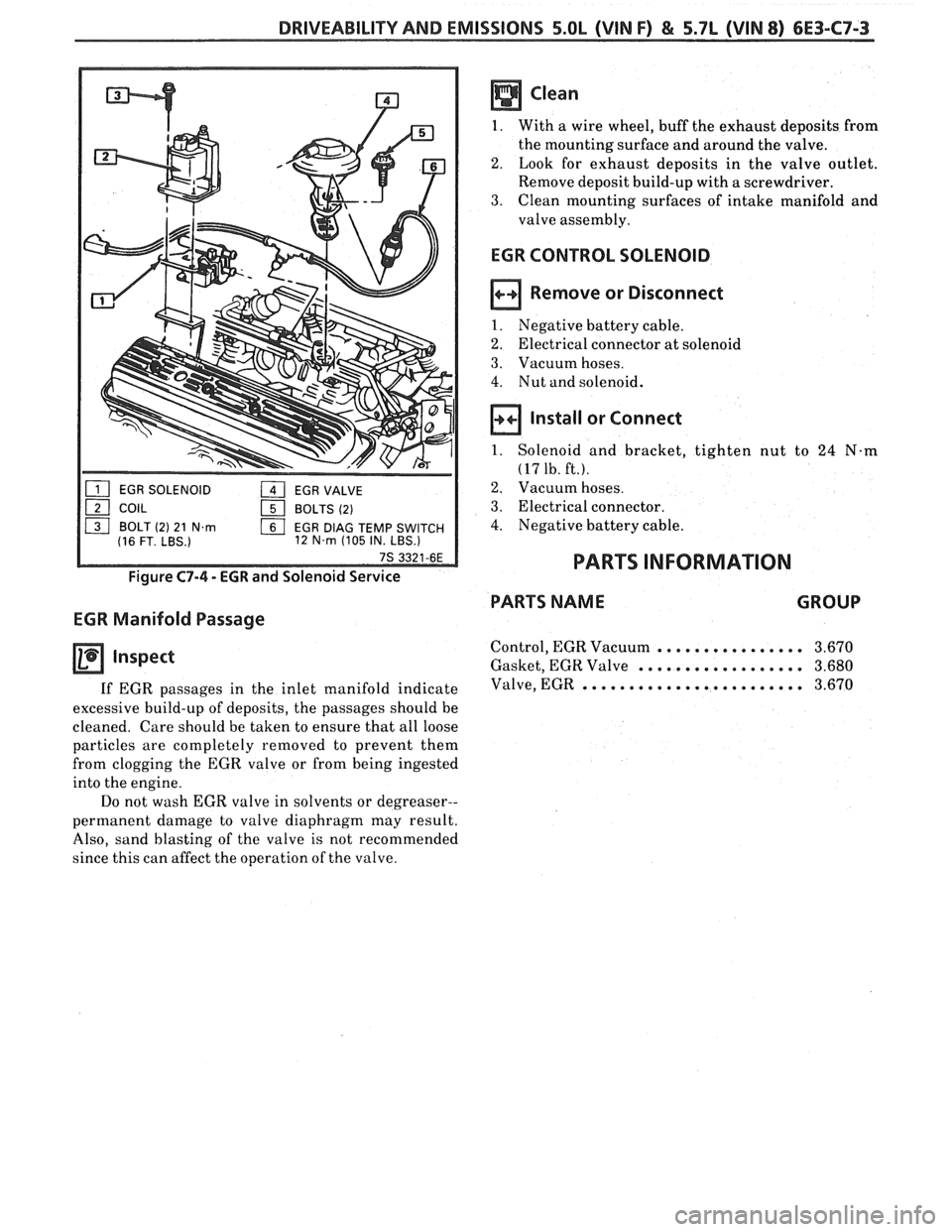
EGR CONTROL SOLENOID
Remove or Disconnect
1. Negative battery cable.
2. Electrical connector at solenoid
3. Vacuum hoses.
4. Nut and solenoid.
Install or Connect
1. Solenoid and bracket, tighten nut to 24 N-m
(17 1b. ft.).
2. Vacuum hoses.
3. Electrical connector.
4. Negative battery cable.
PARTS INFORMATION
PARTS NAME GROUP
Control, EGR Vacuum ................ 3.670
Gasket, EGR Valve .................. 3.680
Valve, EGR ........................ 3.670