1988 PONTIAC FIERO engine oil
[x] Cancel search: engine oilPage 974 of 1825
DRIVEABILIW AND EMISSIONS - FUEL INJECTION 6E-13
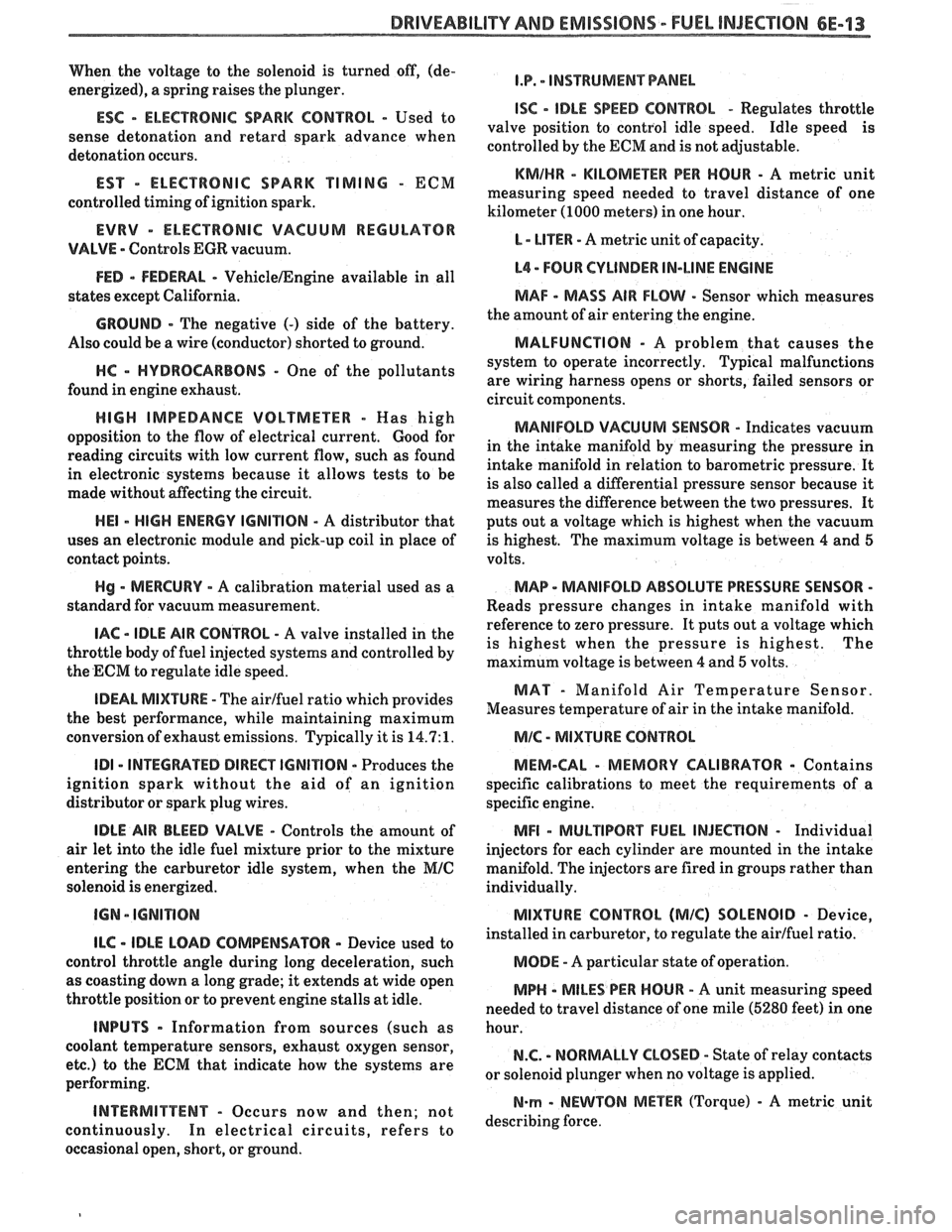
When the voltage to the solenoid is turned off, (de-
energized), a spring raises the plunger.
ESC - ELECTRONIC SPARK CONTROL - Used to
sense detonation and retard spark advance when
detonation occurs.
EST - ELECTRONIC SPARK TIMING - ECM
controlled timing of ignition spark.
EVRV - ELECTRONIC VACUUM REGULAWR
VALVE - Controls EGR vacuum.
FED - FEDEWL - VehicleIEngine available in all
states except California.
GROUND - The negative (-) side of the battery.
Also could be a wire (conductor) shorted to ground.
HC - HYDROCARBONS - One of the pollutants
found in engine exhaust.
HIGH IMPEDANCE VOLTMETER - Mas high
opposition to the flow of electrical current.
Good for
reading circuits with low current flow, such as found
in electronic systems because it allows tests to be
made without affecting the circuit.
HE1 - HIGH ENERGY IGNITION - A distributor that
uses an electronic module and pick-up coil in place of
contact points.
Hg - MERCURY - A calibration material used as a
standard for vacuum measurement.
IAC - IDLE AIR CONTROL - A valve installed in the
throttle body of fuel injected systems and controlled by
the ECM to regulate idle speed.
IDEAL MIXWRE - The airlfuel ratio which provides
the best performance, while maintaining maximum
conversion of exhaust emissions. Typically it is
14.7:1.
ID1 - INTEGRATED DIRECT IGNITION - Produces the
ignition spark without the aid of an ignition
distributor or spark plug wires.
IDLE AIR BLEED VALVE - Controls the amount of
air let into the idle fuel mixture prior to the mixture
entering the carburetor idle system, when the
MIC
solenoid is energized.
ILC - IDLE LOAD COMPENSATOR - Device used to
control throttle angle during long deceleration, such
as coasting down a long grade; it extends at wide open
throttle position or to prevent engine stalls at idle.
INPUTS - Information from sources (such as
coolant temperature sensors, exhaust oxygen sensor,
etc.) to the ECM that indicate how the systems are
performing.
INTERMITTENT - Occurs now and then; not
continuously. In electrical circuits, refers to
occasional open, short, or ground.
I.P. - INSTRUMENT PANEL
ISC - IDLE SPEED CONTROL - Regulates throttle
valve position to control idle speed. Idle speed is
controlled by the ECM and is not adjustable.
KMIHR - KILOMEnR PER HOUR - A metric unit
measuring speed needed to travel distance of one
kilometer (1000 meters) in one hour.
L - LITER - A metric unit of capacity.
L4 - FOUR CYLINDER IN-LINE ENGINE
MAF - MASS AIR FLOW - Sensor which measures
the amount of air entering the engine.
MALFUNCTION - A problem that causes the
system to operate incorrectly. Typical malfunctions
are wiring harness opens or shorts, failed sensors or
circuit components.
MANIFOLD VACUUM SENSOR - Indicates vacuum
in the intake manifold by measuring the pressure in
intake manifold in relation to barometric pressure. It
is also called a differential pressure sensor because
it
measures the difference between the two pressures. It
puts out a voltage which is highest when the vacuum
is highest. The maximum voltage is between 4 and 5
volts.
MAP - MANIFOLD ABSOLUTE PRESSURE SENSOR -
Reads pressure changes in intake manifold with
reference to zero pressure. It puts out a voltage which
is highest when the pressure is highest. The
maximum voltage is between
4 and 5 volts.
MAT - Manifold Air Temperature Sensor.
Measures temperature of air in the intake manifold.
MIC - MIXTURE CONTROL
MEM-CAL
- MEMORY CALIBRATOR - Contains
specific calibrations to meet the requirements of a
specific engine.
MFI - MULTlPORT FUEL INJECnON - Individual
injectors for each cylinder are mounted in the intake
manifold. The injectors are fired in groups rather than
individually.
MIXTURE CONTROL (MIC) SOLENOID - Device,
installed in carburetor, to regulate the airlfuel ratio.
MODE - A particular state of operation.
MPH - MILES PER HOUR - A unit measuring speed
needed to travel distance of one mile (5280 feet) in one
hour.
N.C. - NORMALLY CLOSED - State of relay contacts
or solenoid plunger when no voltage is applied.
N-rn - NEWTON METER (Torque) - A metric unit
describing force.
Page 975 of 1825
6E-14 DRIVEABILITY AND EMISSIONS - FUEL INJECTION
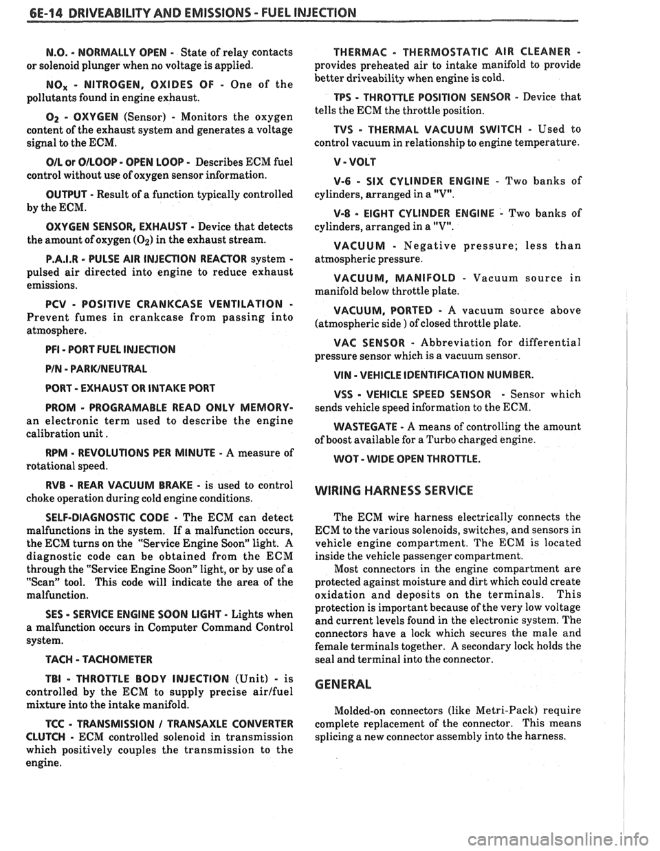
N.O. - NORMALLY OPEN - State of relay contacts
or solenoid plunger when no voltage
is applied.
NOx - NITROGEN, OXIDES OF - One of the
pollutants found in engine exhaust.
O2 - OXYGEN (Sensor) - Monitors the oxygen
content of the exhaust system and generates a voltage
signal to the ECM.
OIL or OILOOP - OPEN LOOP - Describes ECM fuel
control without use of oxygen sensor information.
OUTPUT - Result of a function typically controlled
by the ECM.
OXYGEN SENSOR. EXHAUST - Device that detects
the amount of oxygen
(02) in the exhaust stream.
P.A.1.R - PULSE AIR INJECTION REACTOR system -
pulsed air directed into engine to reduce exhaust
emissions.
PCV - POSITIVE CRANKCASE VENTILATION -
Prevent fumes in crankcase from passing into
atmosphere.
PFI - PORT FUEL INJECTION
PIN
- PARWNEUTWL
PORT - EXHAUST OR INTAKE PORT
PROM
- PROGRAMABLE READ ONLY MEMORY-
an electronic term used to describe the engine
calibration unit
.
RPM - REVOLUTIONS PER MINUTE - A measure of
rotational speed.
RVB - REAR VACUUM BMKE - is used to control
choke operation during cold engine conditions.
SELF-DIAGNOSTIC CODE - The ECM can detect
malfunctions in the system.
If a malfunction occurs,
the ECM turns on the "Service Engine Soon" light.
A
diagnostic code can be obtained from the ECM
through the "Service Engine Soon" light, or by use of a
"Scan" tool. This code will indicate the area of the
malfunction.
SES - SERVICE ENGINE SOON LIGHT - Lights when
a malfunction occurs in Computer Command Control
system.
TACH - TACHOMETER
TBI
- THROTTLE BODY INJECTION (Unit) - is
controlled by the ECM to supply precise airlfuel
mixture into the intake manifold.
TCC - TWNSMISSION I TRANSAXLE CONVERTER
CLUTCH
- ECM controlled solenoid in transmission
which positively couples the transmission to the
engine.
THERMAC - THERMOSTATIC AIR CLEANER -
provides preheated air to intake manifold to provide
better driveability when engine
is cold.
TPS - THROnLE POSITION SENSOR - Device that
tells the ECM the throttle position.
TVS - THERMAL VACUUM SWITCH - Used to
control vacuum in relationship to engine temperature.
V - VOLT
V-6 - SIX CYLINDER ENGINE - Two banks of
cylinders, arranged in a
"V".
V-8 - EIGHT CYLINDER ENGINE - Two banks of
cylinders, arranged in a
"V".
VACUUM - Negative pressure; less than
atmospheric pressure.
VACUUM, MANIFOLD - Vacuum source in
manifold below throttle plate.
VACUUM, PORTED - A vacuum source above I (atmospheric side ) of closed throttle plate. , I
WAC SENSOR - Abbreviation for differential
pressure sensor which is a
vacuum sensor.
VIN - VEHICLE IDENTIFIUTION NUMBER. 1
VSS - VEHICLE SPEED SENSOR - Sensor which
sends vehicle speed information to the ECM.
WASTECATE - A means of controlling the amount
of boost available for a Turbo charged engine.
WOT- WIDE OPEN THROPTLE. I
WIRING HARNESS SERVICE I
The ECM wire harness electrically connects the
ECM to the various solenoids, switches, and sensors in
vehicle engine compartment. The ECM is located
inside the vehicle passenger compartment.
Most connectors in the engine compartment are
protected against moisture and dirt which could create
oxidation and deposits on the terminals. This
protection is important because of the very low voltage
and current levels found in the electronic system. The
connectors have a lock which secures the male and
female terminals together. A secondary lock holds the
seal and terminal into the connector.
GENERAL
Molded-on connectors (like Metri-Pack) require
complete replacement of the connector. This means
splicing a new connector assembly into the harness.
Page 992 of 1825
HYDRAULIC DIAGNOSIS 700434-3
- The first to second gear shift point
- The second to third gear shift point
MANUAL SECOND (2)
2. With vehicle stopped, place gear selector in
"Second" (2) and accelerate to observe:
- The first to second gear shift point
3. Accelerate to 25 MPH (40 KPH) and observe:
- That a second to third gear shift does not
occur
- That TCC does not engage
MANUAL FIRST (I)
1. With vehicle stopped, place gear selector in
"First" (1) and accelerate to 15 MPH (24
KPH)
and observe:
- That no uoshift occurs
- That TCC does
REVERSE
1. With
vehicle stopped, place gear selector in
"Reverse" (R) and slowly accelerate to observe
reverse gear operation.
All possible throttle positions and corresponding
MPH shift point information has not been
provided.
TRANSMISSION PRESSURE CHECK
PROCEDURE
Inspect
e Fluid level
e TV cable adjustment
e Manual linkage
e Engine mechanical, emissions, electrical and fuel
delivery systems
not engage
Install or Connect (Figure 3)
a Oil pressure gage
a Tachometer
Page 995 of 1825
700-R4-6 HYDRAULIC DIAGNOSIS
L PRESSURE CHECK NFORMAT
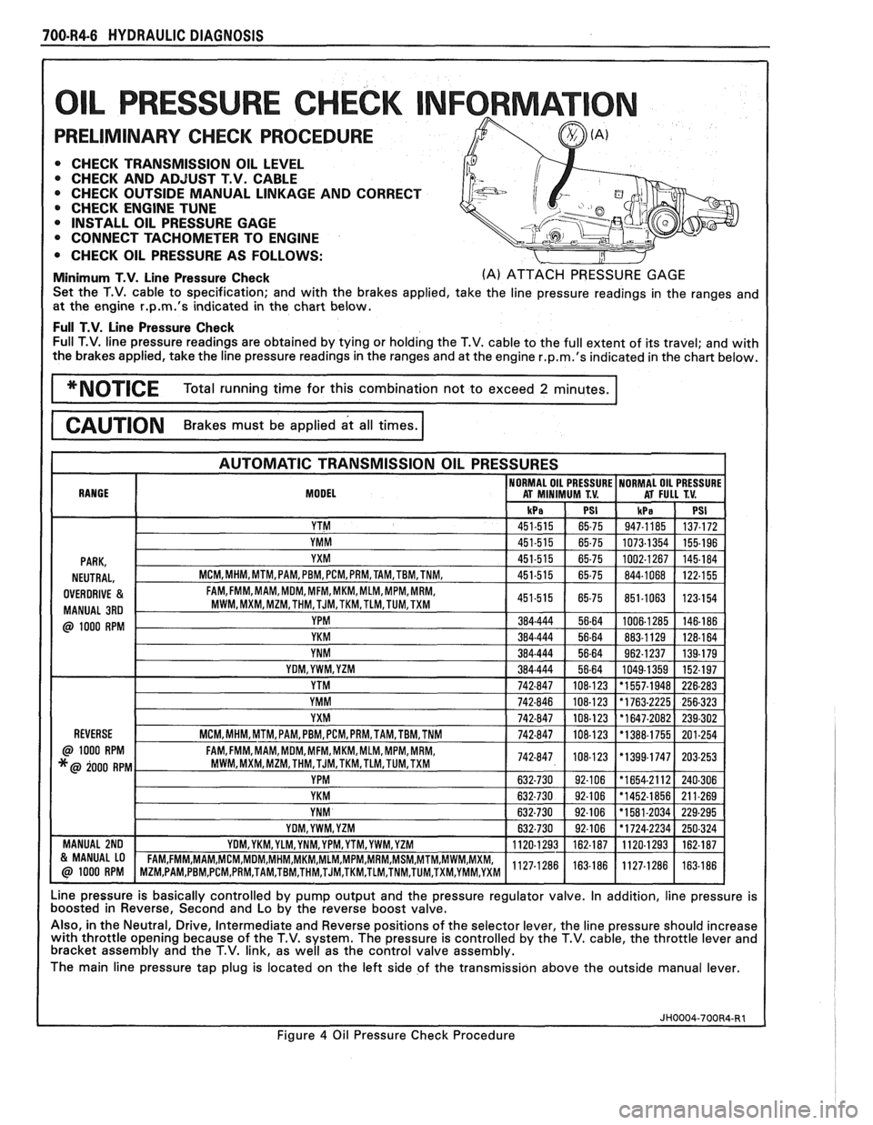
PRELIMINARY CHECK PROCEDURE
0 CHECK TRANSMISSION OIL LEVEL 0 CHECK AND ADJUST T.V. CABLE
0 CHECK OUTSIDE MANUAL LINKAGE AND CORRECT
@ CHECK ENGINE TUNE
0 INSTALL OIL PRESSURE GAGE
CONNECT TACHOMETER TO ENGINE
0 CHECK OIL PRESSURE AS FOLLOWS:
Minimum T.V. Line Pressure Check (A) ATTACH PRESSURE GAGE
Set the T.V. cable to specification; and with the brakes applied, take the line pressure readings in the ranges and
at the engine
r.p.m.'s indicated in the chart below.
Full T.V. Line Pressure Check Full T.V. line pressure readings are obtained by tying or holding the T.V. cable to the full extent of its travel; and with
the brakes applied, take the line pressure readings in the ranges and at the engine
r.p.m.'s indicated in the chart below.
MODEL
Line pressure is basically controlled by pump output and the pressure regulator valve. In addition, line pressure is
boosted in Reverse, Second and Lo by the reverse boost valve.
Also, in the Neutral, Drive, Intermediate and Reverse positions of the selector lever, the line pressure should increase
with throttle opening because of the T.V. system. The pressure is controlled by the T.V. cable, the throttle lever and
bracket assembly and the T.V. link, as well as the control valve assembly.
The main line pressure tap plug is located on the left side of the transmission above the outside manual lever.
Figure
4 Oil Pressure Check Procedure
Page 997 of 1825
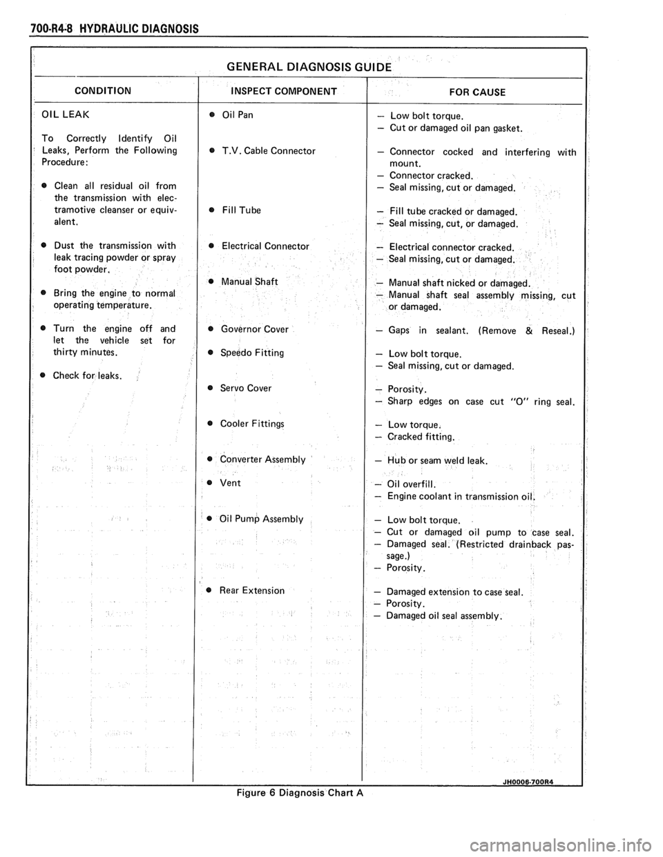
700-R4-8 HYDRAULIC DIAGNOSIS
OIL LEAK - Low bolt torque.
- Cut or damaged oil pan gasket.
To Correctly Identify Oil
Leaks, Perform the Following
T.V. Cable Connector - Connector cocked and interfering with
Procedure:
- Connector cracked.
0 Clean all residual oil from - Seal missing, cut or damaged.
the transmission with
elec-
tramotive cleanser or equiv- - Fill tube cracked or damaged.
alent.
- Seal missing, cut, or damaged.
0 Dust the transmission with 0 Electrical Connector - Electrical connector cracked.
leak tracing powder or spray
- Seal missing, cut or damaged.
foot powder.
@ Manual Shaft - Manual shaft nicked or damaged.
Bring the engine to normal
- Manual shaft seal assembly missing, cut
operating temperature.
Turn the engine off and Governor Cover
- Gaps in sealant. (Remove & Reseal.)
let the vehicle set for
Speedo Fitting
- Low bolt torque.
- Seal missing, cut or damaged.
Check for leaks.
@ Servo Cover
Cooler Fittings
- Cracked fitting.
0 Converter Assembly - Hub or seam weld leak.
- Oil overfill.
- Engine coolant in transmissio
0 Oil Pump Assembly
Rear Extension
- Damaged extension to case seal.
Figure
6 Diagnosis Chart A
Page 999 of 1825
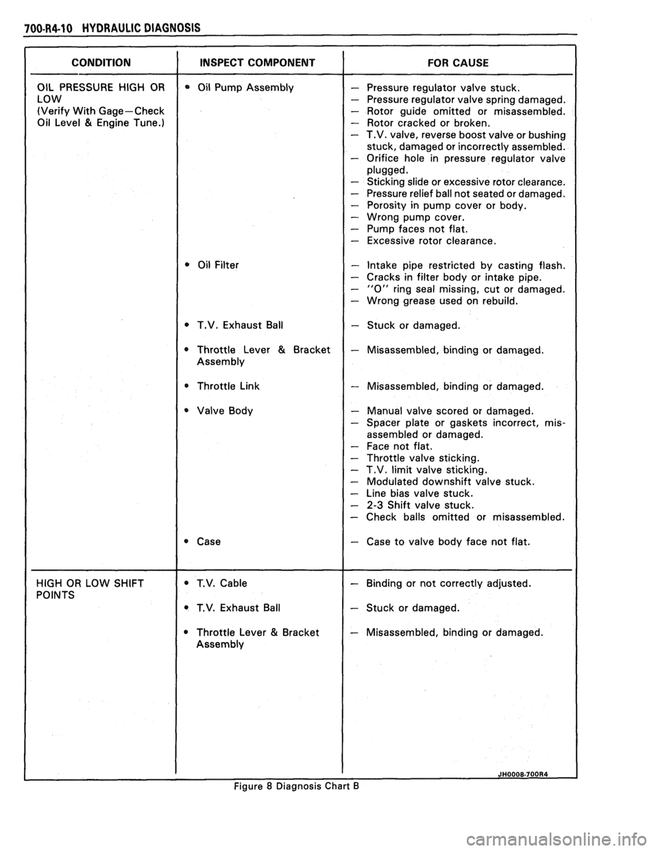
100.R4.10 HYDRAULIC DIAGNOSIS
(Verify With Gage-Check - Rotor guide omitted or misassembled.
Oil Level
81 Engine Tune.) - Rotor cracked or broken. - T.V. valve, reverse boost valve or bushing
stuck, damaged or incorrectly assembled.
- Orifice hole in pressure regulator valve
- Sticking slide or excessive rotor clearance.
- Pressure relief ball not seated or damaged.
- Porosity in pump cover or body.
- Wrong pump cover.
- Pump faces not flat.
- Excessive rotor clearance.
- Intake pipe restricted by casting flash.
- Cracks in filter body or intake pipe.
- "0" ring seal missing, cut or damaged.
- Wrong grease used on rebuild.
T.V. Exhaust Ball
- Stuck or damaged.
* Throttle Link - Misassembled, binding or damaged.
- Manual valve scored or damaged.
- Spacer plate or gaskets incorrect, mis-
assembled or damaged.
- Face not flat.
- Throttle valve sticking.
- T.V. limit valve sticking.
- Modulated downshift valve stuck.
- Line bias valve stuck.
- 2-3 Shift valve stuck.
- Check balls omitted or misassembled.
- Case to valve body face not flat.
T.V. Exhaust Ball
- Stuck or damaged.
Throttle Lever
81 Bracket - Misassembled, binding or damaged.
Figure
8 Diagnosis Chart B
Page 1007 of 1825
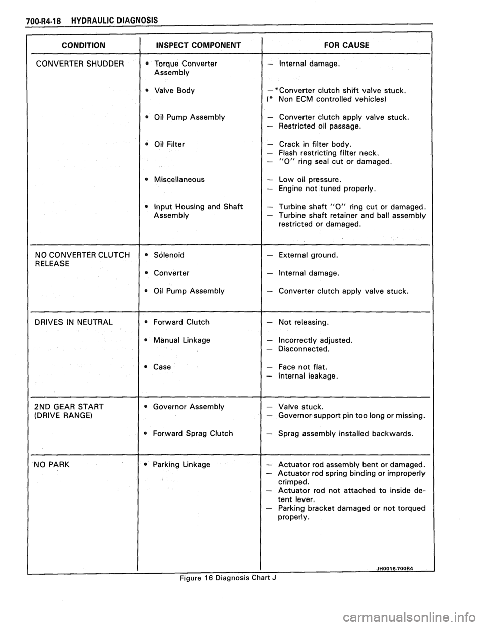
-*Converter clutch shift valve stuck.
(* Non ECM controlled vehicles)
0 Oil Pump Assembly - Converter clutch apply valve stuck.
- Restricted oil passage.
- Crack in filter body.
- Flash restricting filter neck. - "0" ring seal cut or damaged.
0 Miscellaneous - Low oil pressure.
- Engine not tuned properly.
0 Input Housing and Shaft - Turbine shaft "0" ring cut or damaged. - Turbine shaft retainer and ball assembly
restricted or damaged.
- lnternal damage.
Oil Pump Assembly
- Converter clutch apply valve stuck.
0 Manual Linkage - Incorrectly adjusted.
- Disconnected.
- Face not flat.
- lnternal leakage.
pport pin too long or missing.
0 Forward Sprag Clutch Sprag assembly installed backwards.
- Parking bracket damaged or not torqued
Figure
16 Diagnosis Chart J
Page 1010 of 1825
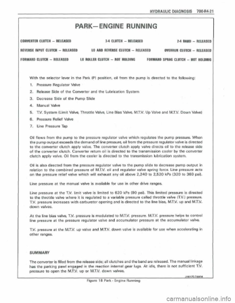
HYDRAULIC DIAGNOSIS 700.R4-21
PARK- ENGlNE RUNNING
CONVERTER CLUTCH - RELEASED 34 CLUTCH - RELEASED 2.4 MUD - RELEASE0
REVERSE INPUT CLUTCH - RELEASED LO AND REVERIE CLUTCH - RELEASED OVERRUN CLUTCH - RELEASE0
FORWARD WUTCH - RELEASED LO ROUM CLUfCH - NOT HOLOlWO FORWARD SPRAQ CLUTCH - NaT HOLDIIYG
With the selector lever in the Park (PI position, oil from the pump is directed to the following:
1. Pressure Regulator Valve
2. Releasg Side of the Converter and the Lubrication System
3, Decrease Side of the Pump Slide
4. Manual Valve
5. T.V. System (Limit Valve, Throttle Valve, Line Bias Valve, M.T.V. Up Valve and M.T.V. Down Valve)
6. Pressure Relief Valve
7. Line Pressure Tap
Oil
flows from the pump to the pressure regulator vatve which regulates the pump pressure. When
the pump output exceeds the demand of line pressure, oil from the pressure regulator valve is directed
to the converter clutch apply valve. The converter clutch apply valve directs oil to the release side
of the converter clutch. Converter return oil is directed to the transmission cooler by the converter
clutch
apply valve, Oil from the cooler is directed to the transmission lubrication system.
Oil is also directed from the pressure regulator valve to the pump slide to decrease pump output in
relation to the combined pressure of M.T.V. oil and regulator valve spring force. Line pressure acts
on the pressure relief valve which will exhaust any oil above 2,240 to 2,520 kPa (320 to 360 psi).
Line pressure at the manual valve is available for use in other drive ranges.
Line pressure at the T.V. limit valv~ is limited to 620 kPa (90 psi). This limited pressure is directed
to the throttle valve where it is regulated to a variable pressure called throttle valve (T.V,) pressurn
T.V. pressure increases with carburetor opening and is directed to the line bias, MXV. up and M.T.V.
down valves.
At the line bias valve, T.V. pressure is modulated to M.T.V. pressure. M.T.V. pressure helps to control
line pressure
at the pressure regulator valve and accumulator pressure at the sceumulator valve.
T.V, pressure at the M.T.V. up valve and M.T,V. down valve js available for use when accelerating in
other ranges.
SUMMARY
The convener is filled from the release side; all clutches and the band are released. The manual linkage
has the parking pawl engaged in the reaction internal gehr lugs. At idle, them is not sufficient T,V.
pressure to open the MXV, up or M.T.V. down vakes.
JHO176.7OOR4 1
Figure 18 Park - Engine Running