1988 PONTIAC FIERO engine oil
[x] Cancel search: engine oilPage 1012 of 1825
HYDRAULIC DIAGNOSIS 700.R4-23
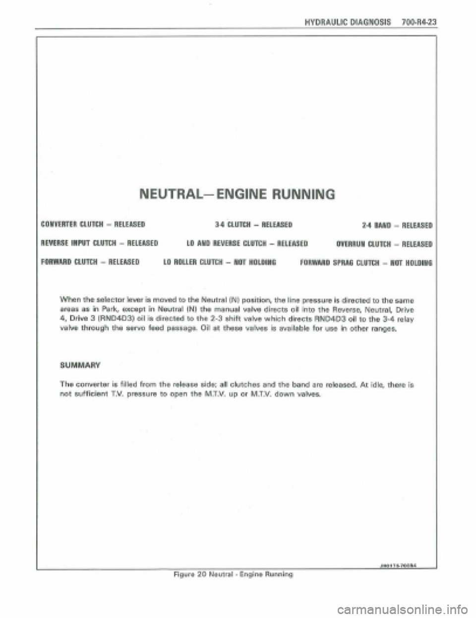
NEUTRAL-- ENGINE RUNNING
34 CLU~H - RELEASED 2.4 MlD - RELEASED COlVERTER CLUTCH - RELEASED
REVERSE IMPU CLUTCH - RELEASED LO MD REVERSE CLUTCH - RELEASED OVERRUN CLUTCH - RELEASED
FORWARD CLUTCH - RELEASED LO ROLLER CLUfCH - MOT HOLDING FORWARD tPRAG CLUTCH - Hm HOLDlWG
When the selector lever Is moved to the Neutral IN1 position, the line pressure is directed to the same
areas as in Park, except in Neutral (N) the manual valve directs oil into the Reverse, Neutral, Drive
4, Drive 3 (RN04031 oil is directed to the 2-3 shift valve which directs RND403 oil to the 3-4 relay
valve through the servo feed passaga Oil at these valves is available for use in other ranges.
SUMMARY
The converter is filled from the release side; all clutches and the band are released, At idle, there is
not sufficient T,V. pressure to open the M.T,V. up or M.T.V. down valves.
I JHO176-fQOR4 Figure 20 Neutral - Engine Running
Page 1020 of 1825
HYDRAULIC DfAQNOSIS 70044-31
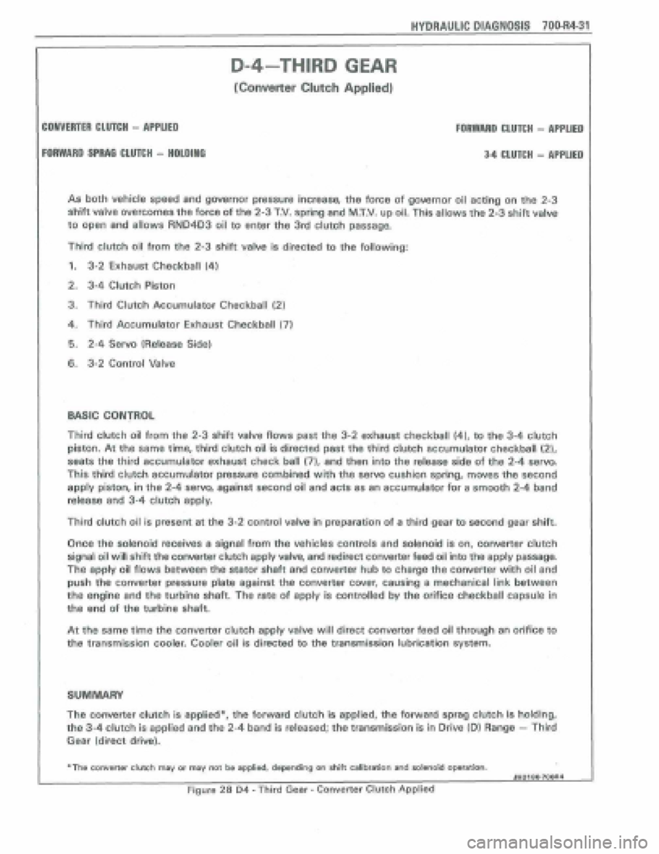
As both vehicle speed and governor pressure increase, the force of gowrnor oil acting on the 2-3
shift valve overcomes the force of the 2-3 T.V. spring and MXV. up oil, This allows the 2-3 shift valve
to
open and allows RN04D3 oil to enter the 3rd clutch passage.
Third clutch oil from the 2-3 shift valve is directed to the following:
1. 3-2 Exhaust Checkball (4)
2. 3-4 Clutch Piston
3. Third Clutch Accumulator Checkball (2)
4. Third Accumulator Exhaust: Checkball (7)
6. 2-4 Servo 1Release Side)
6. 3-2 Control Valve
D-4-THIRD GEAR
[Converter CItPtch Applied)
COMVERTER CtUTCli - APPLIED FOAWARD CLUTCH - APPLIED
FORWARD SFRAG CLU7CH - HPLDINO 34 CLUTCH - APPLIED
Third clutch oil from the 2-3 shift valve flows past the 3-2 exhaust checkball (4), to the 3-4 clutch
piston. At the same time, third clutch oil is directed past the third clutch accumulator checkball {2),
seats the third accumula'tor exhaust check ball (71, and then into the release side of the 2-4 serva
This third clutch accumulator pressure combined with the servo cushion spring, moves the second
apply piston, in the 2-4 servo, against second oil and acts as an accumulator for a smooth 2-4 band
release and 3-4 clutch apply.
Third clutch oil is present at the 3-2 control valve In preparation of a third gear to second gear shift.
Once the solenoid teceives a signal from the vehicles controls and solenoid is on, convefier clutch
signal oil will shift the converter clutch apply valve, and redirect converter feed oil into the apply passage.
the apply oil flows between the stator shaft and converter hub to charge the converter with oil and
push the converter pressure plate against the converter cwer, causing a mechanical link between
the engine and the turbhe shaft. The rate of apply is controlled by the orifice checkball capsule in
tha end of the turbine shaft.
At tho same time the converter clutch appfy valve will direct converter feed oil through an orifice to
the transmission cooler. Cooler oil is directed to the transmission lubrication sysm.
SUMMARY
The converter clutch is applied*, the forward clutch is applied, tho forward sprag clutch is holding,
the 3-4 clutch is applied and the 2-4 band is released; the transmission is in Drive (Dl Range - Third
Gear (direct drive).
+The converter clwh msy or may not be applied, depending on Aitt calibration and salenoid operation. JHOI 80+7OOA4
Figure 28 D4 - Third Gear - Converter Clutch Applkd
Page 1028 of 1825
HYDRAULIC DIAGNOSIS 70044-39
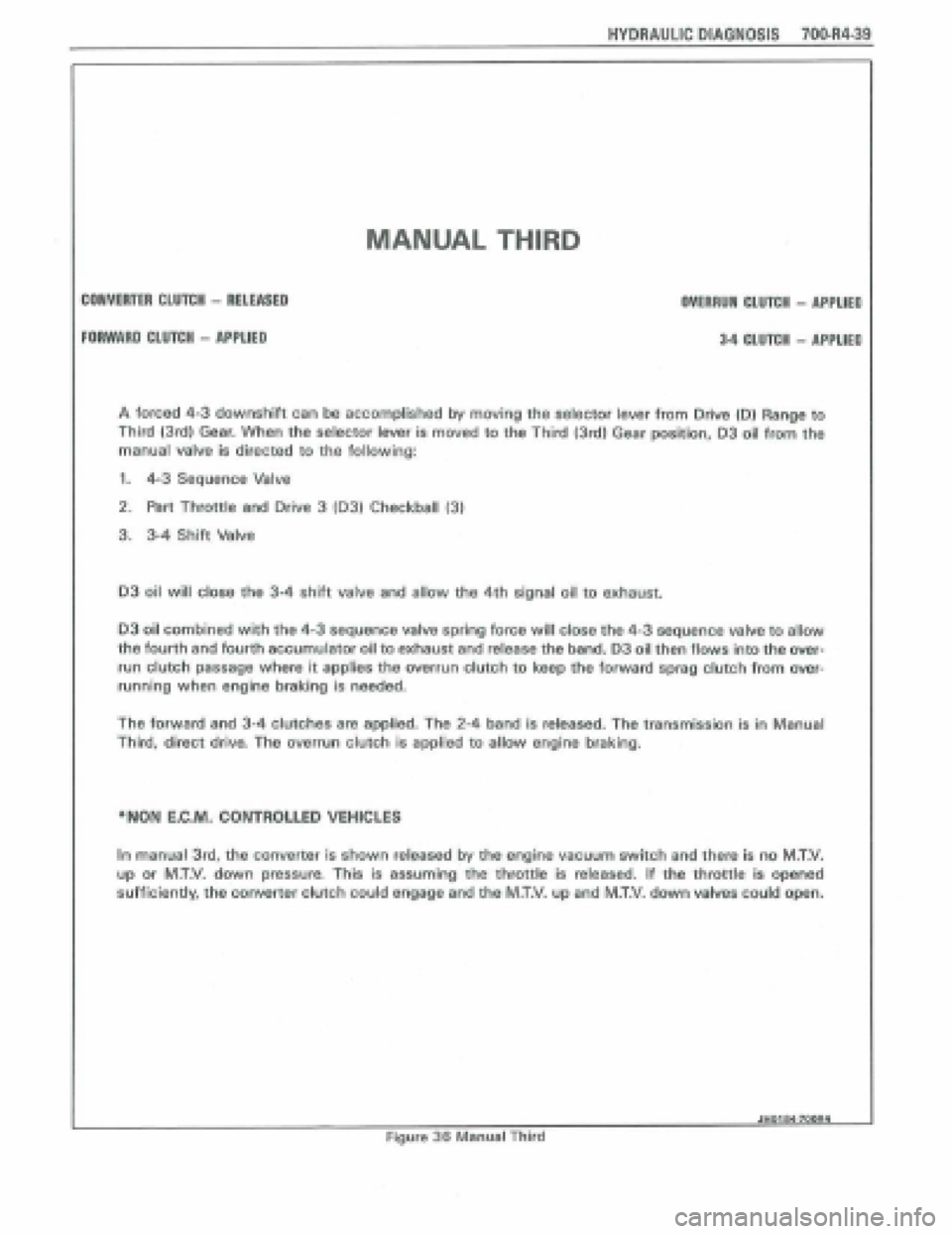
MANUAL THIRD
CONVERTER CLUTCH - RELEASED
FORWARD CLUTCH - APPLIED
OVERRUN CLUTCH - APPUED
3.4 CLUfeH - APPLIEP
A forced 4-3 downshift can be accomplished by moving the selector lever from Drive 10) Range to
Third {3rd) Gear. When the selector lever is moved to the Third (3rd) Gear position, 03 oil from the
manual
valve is directed to the following:
1. 4-3 Sequence Valve
2. Part Throttle and Drive 3 103) Checkball 131
3. 3-4 Shift Valve
03 oil will close the 34 shift valve and allow the 4th signal oil to exhaust.
D3 oil combined with the 4-3 sequence valve spring force will close the 4-3 sequence valve to allow
the fourth and fourth accumulator oil to exhaust and release the band. 03 oil then flows into the over-
run clutch passage where it applies the overrun clutch to keep the forward sprag clutch from over-
running when engine braking is n~eded.
The forward and 3-4 CIU~C~~S are applied. The 2-4 band is released. The transmission is in Manual
Third,
direct driva The overrun clutch is appRad to allow engine braking.
*NON E,C.M, CONTROLLED VEHICLES
In manual 3td, the converter is shown released by the engine vacuum switch and there is no M.T.V.
up or M.T.V. down pressure, This is assuming the throttle is released. If the throttle is opened
sufficiently, the converter clutch could engage and the M.T.V. up and MXV. down valves coJd open.
JHOtOQ7WRI I
Figure 36 Manual Third
Page 1030 of 1825
, HYDRAULIC PlAGNQSlS 7004441
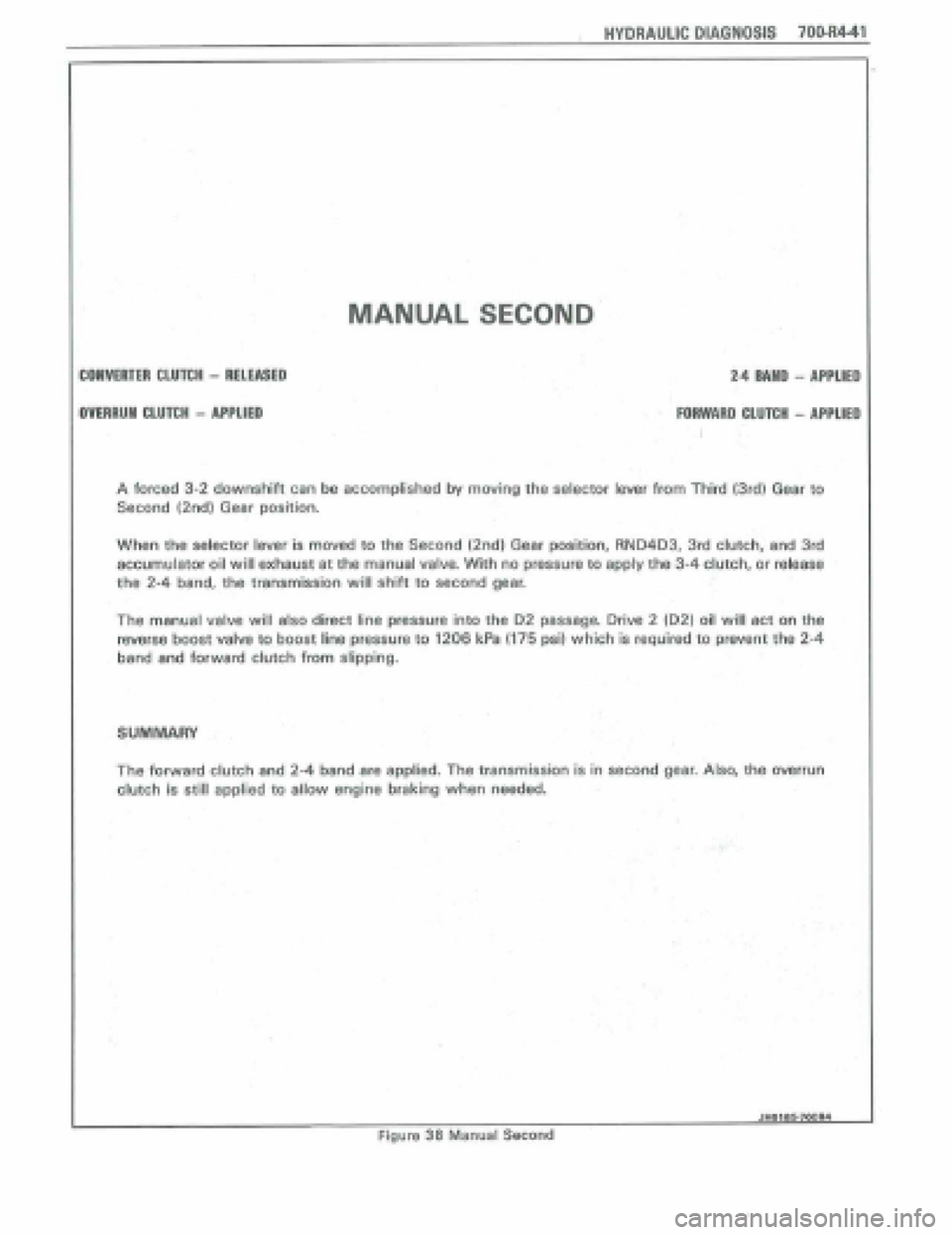
MANUAL SECOND
COWERTER CLUTCH - RELEASED
OVEARUN CLUTCH - APPLIED
2.4 MUD - APPLIED
I
FORWARD CLUTCH - APPLIED
I
A forced 3-2 downshift cen be a~cornplished by moving the selector lever from Third (3rd) Gear to
Second (2nd) Gear position.
When
the selector lever is moved to the Second (2nd) Gear position, RND4D3, 3rd clutch, and 3rd
accumulator oil
will exhaust at the manual valve, With no pressure to apply the 34 clutch, or release
the 2-4 band, the transmission will shift to second gear.
The manual valve will also direct line pressure into the D2 passage, Drive 2 (D2) oil will act on the
reverse boost valve to boost line pressure to 1206 kPa (I75 psi) which is required to prevent the 2-4
band and forward clutch from slipping.
SUMMARY
The forward clutch and 2-4 band are applied. The transmission is in second gear. Also, the werrun
clutch is still applied to allow engine braking when needed.
JHOlUWOOR4 1
Figure 38 Manual Se~ond
Page 1032 of 1825
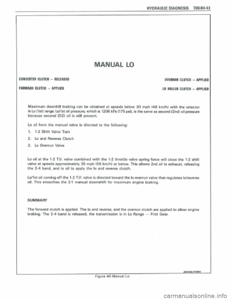
MANUAL LO
CONVERTEM CLUTCH - RELEASED
FORWARD CLUTCH - APPLIED
Maximum downhill braking can be obtained at speeds below 30 mph (48 kmlh) with the selector
in Lo (tat) range. Lollst oil pressure, which is 1206 kR I175 psi), is the same as second (2nd) oil pressure
because second (02) oil is still present.
Lo oil from the manual valve is directed to the following:
1* 1-2 Shift Valvelain
2. to and Reverse Clutch
3. Lo Overrun Valve
Lo oil at the 1-2 T.V. valve combined with the 1-2 throttle valve spring force will close the 1-2 shift
valve at speeds approximately 36 mph 156 km/h) or below. This allows 2nd oil to exhaust, releasing
the 2-4 band, and lo oil to apply the lo and reverse clutch.
Loflst oil coming off the 1-2 T.V* valve is directed toward the lo overrun valve that regulates lolreverse
oil. This smoothes the 2-1 manual downshift for maximum engine braking.
The forward clutch is applied. The lo and reverse, and the overrun clutch are applied to allow engine
braking.
The 2-4 band is released, the transmission is in Lo Range - First Gear.
HYDRAULIC DIAGNOSIS 700-RU3
OVEARUM CLUTCH - APPLIED
LO ROLLER CLUTCH - APPLIED
JH018&7WR4
Figure 40 Manual Lo
Page 1050 of 1825
TORQUE CONVERTER CLUTCH (TCC)
DIAGNOSIS
To properly diagnose the Torque Converter
Clutch (TCC) system, perform all electrical
testing first and then the hydraulic testing. Refer
to the Torque Converter Section
6E2-C8 for
additional information.
The TCC is applied by fluid pressure which is
controlled by a solenoid located inside the Automatic
Transmission assembly. The solenoid is energized or
released by making or breaking an electrical circuit
through a combination of switches and sensors.
TCC Electrical Diagnosis
e For electrical diagnosis of TCC, refer to the
specific vehicle section in Section
8A, Electrical
Diagnosis.
e For diagnosis of emission control related
components of TCC, Refer to the specific section
of
6E, Driveability and Emissions.
e For the diagnosis of TCC Hydraulic Controls,
refer to the Procedure and Wiring Diagrams
provided in this section.
Functional Check Procedure
rn Inspect
1. Install a tachometer
2. Operate the vehicle until proper operating
temperature is reached
3. Drive vehicle at 50-55 mph (80-88 Km/h) with
light throttle (road load)
4. Maintaining throttle lightly touch the brake
pedal and check for a slight bump when the TCC
releases and a slight increase in engine RPM.
5. Release the brake, slowly accelerate and check for
a re-apply of the converter clutch and a slight
decrease in engine RPM.
Preliminary Checking Procedure
The purpose of the preliminary checking
procedure is to isolate external (electrical) problems
from internal (electrical or mechanical) ones.
Important
e Use only a scale type ohmmeter. High impedance
type ohmmeters and those with a digital readout
will not work.
e An ALCL scanner may be used to verify the
electrical circuit. Remember, a completed circuit
does not indicate that the solenoid will apply.
e Do not bench test using an automotive type
battery. Accidentally crossed wires will damage
the internal diodes of the TCC solenoid.
HYDRAULIC DIAGNOSIS 700-R4-61
External Controls
rn Inspect
e Connect voltmeter between transmission
connector and ground.
e Turn key "ON"
e If 0 or low voltage is found, refer to Sections 6E
and 8A for electrical diagnosis.
e If 12 volts are present at the connector, refer to
the TCC hydraulic diagnosis.
TORQUE CONVERTER EVALUATION
Torque Converter Stator
The Torque Converter Stator roller clutch can
have one of two different type malfunctions:
A. Stator Assembly freewheels in both
directions.
B. Stator Assembly remains locked up at all
times.
Condition A-Poor Acceleration Low Speed
The vehicle tends to have poor acceleration from
a standstill. At speeds above 30-35 mph (50-55
km/h),
the car may act normal. If poor acceleration is noted,
it should first be determined that the exhaust system
is not blocked, the engine timing is correct and the
transmission is in first
(1st) gear when starting out.
If the engine freely accelerates to high
r.p.m. in
"NEUTRAL" (N), it can be assumed that the engine
and exhaust system are normal. Checking for poor
performance in "Drive" and Reverse will help
determine if the stator is freewheeling at all times.
Condition B-Poor Acceleration High Speed
Engine r.p.m. and car speed limited or restricted
at high speeds. Performance when accelerating from a
standstill is normal. Engine may over-heat. Visual
examination of the converter may reveal a blue color
from over-heating.
If the converter has been removed, the stator
roller clutch can be checked by inserting a finger into
the splined inner race of the roller clutch and trying to
turn the race in both directions. The inner race should
turn freely clockwise, but not turn or be very difficult
to turn counterclockwise.
The Converter Should Be Replaced If:
e Leaks externally, such as at the hub weld area.
e Converter has an imbalance which cannot be
corrected. (Refer to Converter Vibration Test
Procedure).
e Converter is contaminated with engine coolant
containing antifreeze.
The Converter Should Not Be Replaced If:
e The oil has an odor, is discolored, and there is no
evidence of metal or clutch facing particles.
e The threads in one or more of the three converter
bolt holes are damaged.
- Correct with thread insert. (Refer to Section
6A).
Page 1106 of 1825
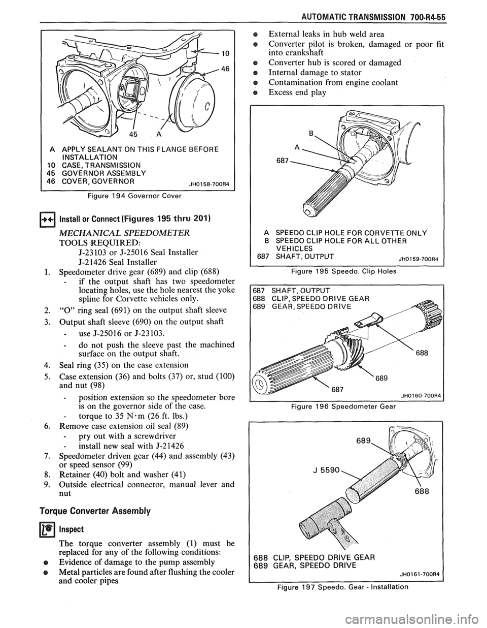
AUTOMATIC TRANSMISSION 700-R4-55
A APPLY SEALANT ON THIS FLANGE BEFORE
INSTALLATION
10 CASE TRANSMISSION
Figure
194 Governor Cover
Install or Connect (Figures 195 thru 201)
MECHANICAL SPEEDOMETER
TOOLS REQUIRED:
J-23 103 or J-25016 Seal Installer
J-21426 Seal Installer
1. Speedometer
drive gear (689) and clip (688)
- if the output shaft has two speedometer
locating holes, use the hole nearest the yoke
spline for Corvette vehicles only.
2. "0" ring seal (691) on the output shaft sleeve
3. Output shaft sleeve (690) on the output shaft
- use J-25016 or J-23103.
- do not push the sleeve past the machined
surface on the output shaft.
4. Seal
ring (35) on the case extension
5. Case extension
(36) and bolts
(37) or, stud (100)
and nut (98)
- position extension so the speedometer bore
is on the governor side of the case.
- torque to 35 N-m (26 ft. lbs.)
6. Remove case extension oil seal (89)
- pry out with a screwdriver
- install new seal with J-21426
7. Speedometer driven gear (44) and assembly (43)
or speed sensor (99)
8. Retainer (40) bolt and washer (41)
9. Outside
electrical connector, manual lever and
nut
Torque Converter Assembly
Inspect
The torque converter assembly (1) must be
replaced for any of the following conditions:
e Evidence of damage to the pump assembly
e Metal particles are found after flushing the cooler
and cooler pipes
a External leaks in hub weld area
e Converter pilot is broken, damaged or poor fit
into crankshaft
e Converter hub is scored or damaged
Internal damage to stator
e Contamination from engine coolant
a Excess end play
A SPEEDO CLlP HOLE FOR CORVETTE ONLY
B SPEEDO CLlP HOLE FOR ALL OTHER
VEHICLES
Figure
195 Speedo. Clip Holes
688 CLIP, SPEEDO DRIVE GEAR
689 GEAR, SPEEDO DRIVE
Figure 196 Speedometer Gear
688 CLIP, SPEEDO DRIVE GEAR
689 GEAR, SPEEDO DRIVE
Figure 197 Speedo. Gear
- Installation
Page 1117 of 1825
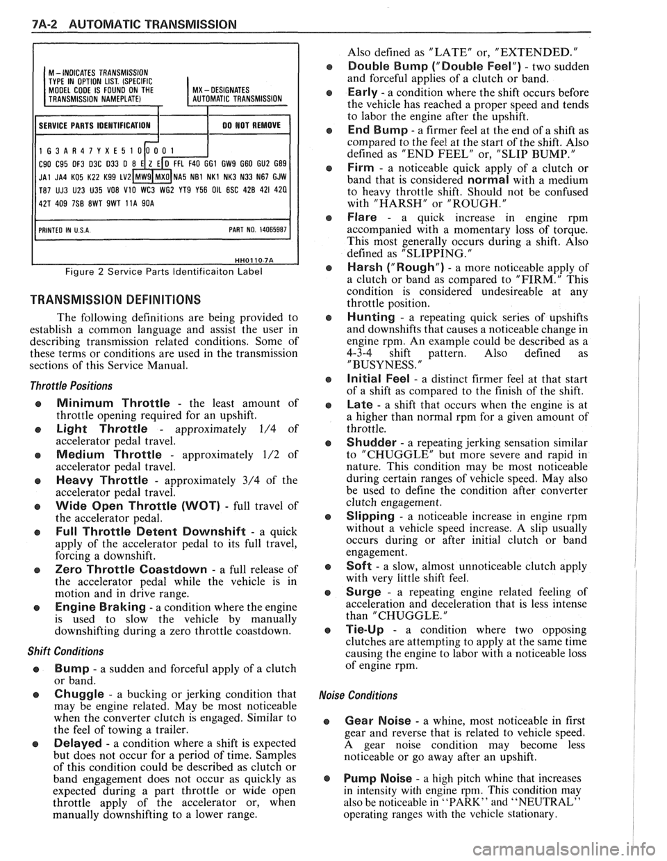
7A-2 AUTOMATIC TRANSMISSION
I I
M - INDICATES TRANSMISSION
TYPE IN OPTION LIST. (SPECIFIC MODEL CODE IS FOUND ON THE I MX - DESIGNATES
11 SERVICE PARTS IDEMTIFICATIOM I 1 00 MOT REMOVE I
1G3AR47YXE5
C90 C95 DF3 D3C 033 0 GI GW9 G60 GU2 G89
JAl JA4 KO5 K22 Kg9 LV2 NA5 NB1 NKl NK3 N33 N67 GJW
T87 UJ3 U23 U35
VO8 V10 WC3 WG2 YT9 Y56 OIL 6SC 428 421 420
Figure 2 Service Parts ldentificaiton Label
TRANSMISSION DEFINITIONS
The following definitions are being provided to
establish a common language and assist the user in
describing transmission related conditions. Some of
these terms or conditions are used in the transmission
sections of this Service Manual.
Throttle Positions
Minimum Throttle - the least amount of
throttle opening required for an upshift.
Light Throttle - approximately 1/4 of
accelerator pedal travel.
Medium Throttle - approximately 1/2 of
accelerator pedal travel.
Heavy Throttle - approximately 3/4 of the
accelerator pedal travel.
Wide Open Throttle (WOT) - full travel of
the accelerator pedal.
Full Throttle Detent Downshift - a quick
apply of the accelerator pedal to its full travel,
forcing a downshift.
Zero Throttle Coastdown - a full release of
the accelerator pedal while the vehicle is in
motion and in drive range.
Engine Braking - a condition where the engine
is used to slow the vehicle by manually
downshifting during a zero throttle coastdown.
Shift Conditions
'a Bump - a sudden and forceful apply of a clutch
or band.
Q Chuggle - a bucking or jerking condition that
may be engine related. May be most noticeable
when the converter clutch is engaged. Similar to
the feel of towing a trailer.
e Delayed - a condition where a shift is expected
but does not occur for a period of time. Samples
of this condition could be described as clutch or
band engagement does not occur as quickly as
expected during a part throttle or wide open
throttle apply of the accelerator or, when
manually downshifting to a lower range. Also
defined as "LATE" or, "EXTENDED."
Double Bump ("Double Feel") - two sudden
and forceful applies of a clutch or band.
Early - a condition where the shift occurs before
the vehicle has reached a proper speed and tends
to labor the engine after the upshift.
End Bump - a firmer feel at the end of a shift as
compared to the feel at the start of the shift. Also
defined as "END FEEL" or, "SLIP BUMP."
Firm - a noticeable quick apply of a clutch or
band that is considered
normal with a medium
to heavy throttle shift. Should not be confused
with "HARSH" or "ROUGH."
Flare - a quick increase in engine rpm
accompanied with a momentary loss of torque.
This most generally occurs during a shift. Also
defined as "SLIPPING.
"
Harsh ("Rough") - a more noticeable apply of
a clutch or band as compared to "FIRM." This
condition is considered undesireable at any
throttle position.
Hunting - a repeating quick series of upshifts
and downshifts that causes a noticeable change in
engine rpm. An example could be described as a
4-3-4 shift pattern. Also defined as
"BUSYNESS.
"
Initial Feel - a distinct firmer feel at that start
of a shift as compared to the finish of the shift.
Late - a shift that occurs when the engine is at
a higher than normal rpm for a given amount of
throttle.
Shudder - a repeating jerking sensation similar
to "CHUGGLE" but more severe and rapid in
nature. This condition may be most noticeable
during certain ranges of vehicle speed. May also
be used to define the condition after converter
clutch engagement.
Slipping - a noticeable increase in engine rpm
without a vehicle speed increase.
A slip usually
occurs during or after initial clutch or band
engagement.
Soft - a slow, almost unnoticeable clutch apply
with very little shift feel.
Surge - a repeating engine related feeling of
acceleration and deceleration that is less intense
than "CHUGGLE.
"
Tie-Up - a condition where two opposing
clutches are attempting to apply at the same time
causing the engine to labor with a noticeable loss
of engine rpm.
,e Conditions
Gear Noise - a whine, most noticeable in first
gear and reverse that is related to vehicle speed.
A gear noise condition may become less
noticeable or go away after an upshift.
Pump Noise - a high pitch whine that increases
in intensity with engine
rpm. This condition may
also be noticeable in
"PARK" and "NEUTRAL"
operating ranges with the vehicle stationary.