1988 PONTIAC FIERO engine oil
[x] Cancel search: engine oilPage 1167 of 1825
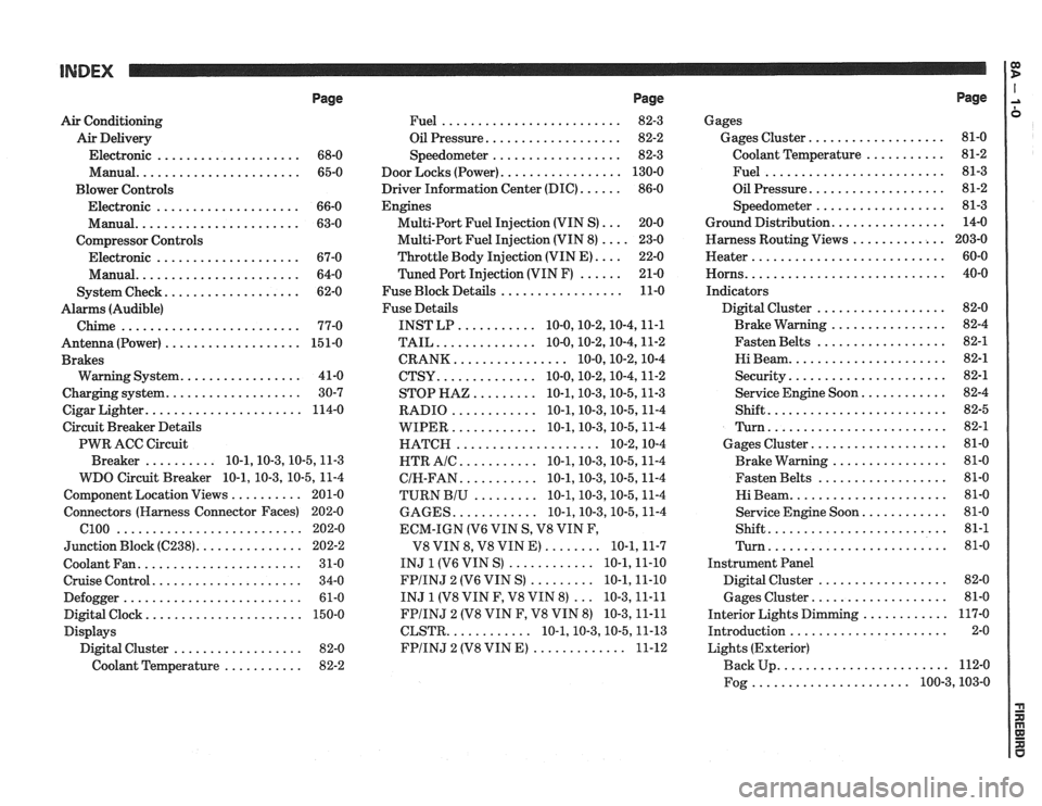
Page
Air Conditioning
Air Delivery
Electronic
.................... 68-0
Manual
....................... 65-0
Blower Controls
Electronic
.................... 66-0
Manual
....................... 63-0
Compressor Controls Electronic
.................... 67-0
Manual
....................... 64-0
................... System Check 62-0
Alarms (Audible)
Chime
......................... 77-0
Antenna(Power) ................... 151-0
Brakes
................. Warning System 41-0
................... Charging system 30-7
...................... Cigar Lighter 114-0
Circuit Breaker Details
PWR ACC Circuit
.......... Breaker 10.1.10.3.10.5.1 1.3
WDO Circuit Breaker
10.1. 10.3. 10.5. 11-4
.......... Component Location Views 201-0
Connectors (Harness Connector Faces) 202-0
el00 .......................... 202-0
............... Junction Block ((2238) 202-2
Coolant Fan
....................... 31-0
Cruise Control
..................... 34-0
Defogger
......................... 61-0
Digital Clock
...................... 150-0
Displays Digital Cluster
.................. 82-0
Coolant Temperature
........... 82-2
Page
......................... Fuel 82-3
................... Oil Pressure 82-2
.................. Speedometer 82-3
................. Door Locks (Power) 130-0
...... Driver Information Center (DIC) 86-0
Engines
... Multi-Port Fuel Injection (VIN S) 20-0
.... Multi-Port Fuel Injection (VIN 8) 23-0
.... Throttle
Body Injection (VIN E) 22-0
...... Tuned
Port Injection (VIN F) 21-0
................. Fuse Block Details 11-0
Fuse Details
........... INST LP 10.0.10.2.10.4.1 1.1
.............. TAIL 10.0.10.2.10.4.1 1.2
................ CRANK 10.0.10.2.1 0.4
.............. CTSY 10~0.10.2.10.4.1 1.2
......... STOP HAZ 10.1.10.3.10.5.1 1.3
............ RADIO 10.1.10.3.10.5.1 1.4
............ WIPER 10.1.10.3.10.5.1 1.4
.................... HATCH 10.2.1 0.4
........... HTR AlC 10.1.10.3.10.5.1 1.4
........... CIH.FAN 10.1.10.3.10.5.1 1.4
......... TURN BIU 10.1.10.3.10.5.1 1.4
............ GAGES 10.1.10.3.10.5.1 1.4
ECM-IGN
(V6 VIN S. V8 VIN F.
........ V8 VIN 8. V8 VIN E) 10.1.1 1.7
............ INJ 1 (V6 VIN S) 10.1.1 1.10
......... FPIINJ 2 (V6 VIN S) 10.1.1 1.10
... INJ 1 (V8 VIN F. V8 VIN 8) 10.3.1 1.11
FPIINJ 2 (V8 VIN F. V8 VIN 8) 10.3.1 1.11
............ CLSTR 10.1.10.3.10.5.1 1.13
............. FPIINJ 2 (V8 VIN E) 11-12
Page
Gages
................... Gages Cluster 81-0
........... Coolant Temperature 81-2
......................... Fuel 81-3
................... Oil Pressure 81-2
.................. Speedometer 81-3
................ Ground Distribution 14-0
Harness Routing Views
............. 203-0
........................... Heater 60-0
............................ Horns 40-0
Indicators
.................. Digital Cluster 82-0
................ Brake Warning 82-4
.................. Fasten Belts 82-1
...................... Hi Beam 82-1
...................... Security 82-1
............ Service Engine Soon 82-4
......................... Shift 82-5
......................... Turn 82-1
................... Gages Cluster 81-0
................ Brake Warning 81-0
.................. Fasten Belts 81-0
...................... Hi Beam 81-0
............ Service Engine Soon 81-0
......................... Shift 81-1
......................... Turn 81-0
Instrument Panel
Digital Cluster
.................. 82-0
Gages Cluster
................... 81-0
............ Interior Lights Dimming 117-0
...................... Introduction 2-0
Lights (Exterior)
........................ Back Up 112-0
...................... Fog 100.3,10 3.0
Page 1211 of 1825
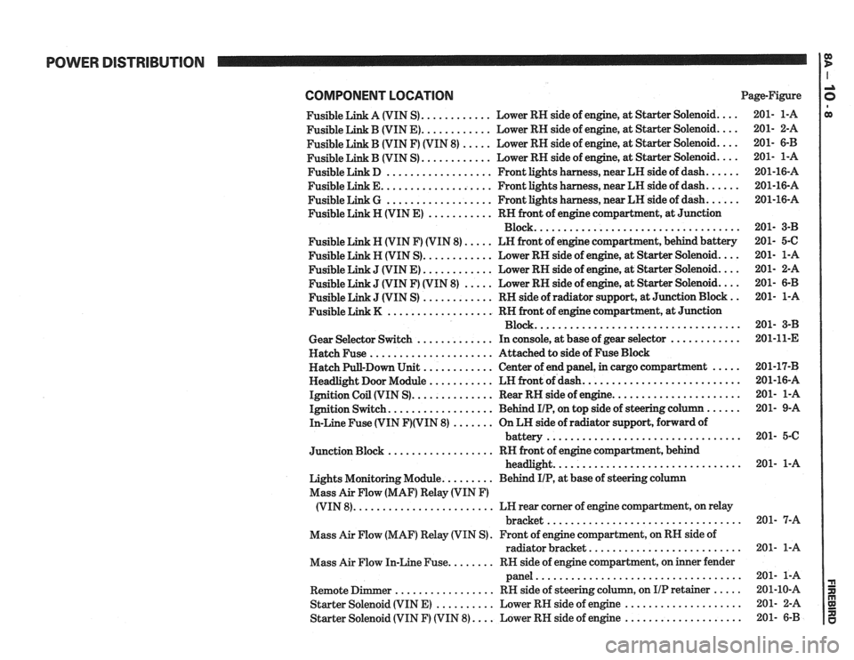
POWER DISTRIBUTION
COMPONENT LOCATlON Page-Figure
Fusible Link A (VIN S)
............ Lower RH side of engine. at Starter Solenoid ....
Fusible Link B (VIN E) ............ Lower RH side of engine. at Starter Solenoid ....
Fusible Link B (VIN F) (VIN 8) ..... Lower RH side of engine. at Starter Solenoid ....
............ Fusible Link B (VIN S) Lower
RH side of engine. at Starter Solenoid ....
Fusible Link D .................. Front lights harness. near LH side of dash ......
Fusible Link E ................... Front lights harness. near LH side of dash ......
Fusible Link G .................. Front lights harness. near LH side of dash ......
Fusible Link H (VIN E) ........... RH front of engine compartment. at Junction
Block
...................................
Fusible Link N (VIN F) (VIN 8) ..... LN front of engine compartment. behind battery
Fusible Link H (VIN S)
............ Lower RH side of engine. at Starter Solenoid ....
J (VIN E) ............ Lower RH side of engine, at Starter Solenoid ....
J (VIN F) (VIN 8) ..... Lower RH side of engine, at Starter Solenoid ....
J (VIN S) ............ RH side of radiator support. at Junction Block ..
.................. Fusible Link K RN front of engine compartment. at Junction
Block
...................................
Gear Selector Switch ............. In console, at base of gear selector ............
Hatch Fuse ..................... Attached to side of Fuse Block
Hatch Pull-Down Unit
............ Center of end panel, in cargo compartment .....
Headlight Door Module ........... LH front of dash ...........................
Ignition Coil (VIN S) .............. Rear RH side of engine ......................
Ignition Switch .................. Behind IIP. on top side of steering column ......
In-Line Fuse (VIN F)(VIN 8) ....... On LH side of radiator support. forward of
................................. battery
.................. Junction Block RH front of engine compartment. behind
................................ headlight
Lights Monitoring Module
......... Behind IIP. at base of steering column
Mass Air Flow (MAF) Relay (VIN
F)
........................ (VIN 8) LH rear corner of engine compartment, on relay
................................. bracket
Mass Air Flow (MAF) Relay (VIN S)
. Front of engine compartment. on RH side of
radiator bracket
..........................
Mass Air Flow In-Line Fuse ........ RN side of engine compartment, on inner fender
panel
...................................
Remote Dimmer ................. RH side of steering column. on IIP retainer .....
Starter Solenoid (VIN E) .......... Lower RH side of engine ....................
Starter Solenoid (VIN F) (VIN 8) .... Lower RH side of engine ....................
Page 1250 of 1825
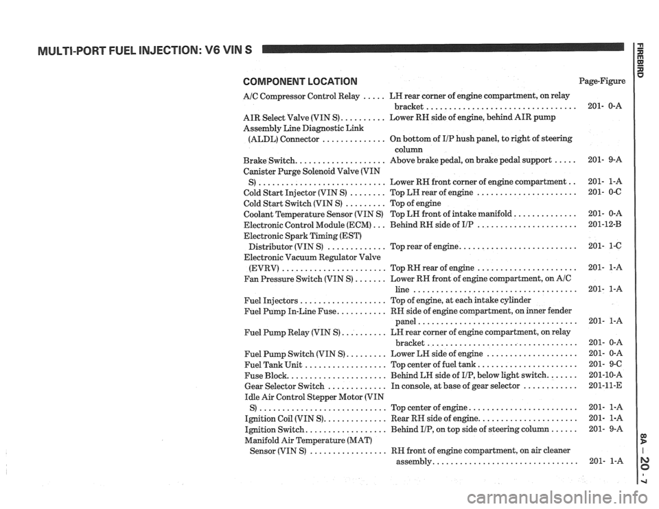
MULTI-PORT FUEL INJECTION: V6 VIN S
COMPONENT LOCATION
AIC Compressor Control Relay ..... LH rear corner of engine compartment, on relay
................................. bracket
AIR Select Valve (VIN S)
.......... Lower RN side of engine, behind AIR pump
Assembly Line Diagnostic Link
(ALDL) Connector
.............. On bottom of IIP hush panel, to right of steering
column
Brake Switch.
................... Above brake pedal, on brake pedal support .....
Canister Purge Solenoid Valve (VIN
............................ .. S) Lower RH front
corner of engine compartment
Cold Start Injector (VIN S)
........ Top LH rear of engine ......................
Cold Start Switch (VIN S) ......... Top of engine
Coolant Temperature Sensor (VIN S) Top LN front of intake manifold.
.............
Electronic Control Module (ECM) ... Behind RH side of IIP ......................
Electronic Spark Timing (EST)
......................... Distributor (VIN S) ............. Top rear of engine.
Electronic Vacuum Regulator Valve
(EVRV)
....................... TopRHrearofengine ......................
Fan Pressure Switch (VIN S) ....... Lower RH front of engine compartment, on AIC
line ....................................
Fuel Injectors ................... Top of engine, at each intake cylinder
Fuel Pump In-Line Fuse.
.......... RH side of engine compartment, on inner fender
panel
...................................
Fuel Pump Relay (VIN S) .......... LH rear corner of engine compartment, on relay
................................. bracket
Fuel Pump Switch (VIN S)
......... Lower LH side of engine ....................
Fuel Tank Unit .................. Top center of fuel tank ......................
Fuse Block. ..................... Behind LH side of IIP, below light switch. ......
Gear Selector Switch ............. In console, at base of gear selector ............
Idle Air Control Stepper Motor (VIN
S)
............................ Topcenterofengine ........................
Ignition Coil (VIN S). ............. Rear RH side of engine. .....................
Ignition Switch. ................. Behind IIP, on top side of steering column ......
Manifold Air Temperature (MAT)
................. Sensor (VIN S) RH front of engine compartment, on air cleaner
............................... assembly. Page-Figure
Page 1264 of 1825
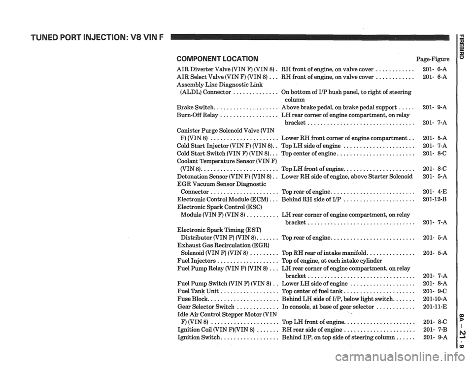
COMPONENT LOCATION Page-Figure
AIR Diverter Valve (VIN F) (VIN 8)
. RN front of engine, on valve cover ............ 201- 6-A
AIR Select Valve (VIN F) (VIN 8)
... RN front of engine, on valve cover ............ 201- 6-A
Assembly Line Diagnostic Link
(ALDL) Connector
.............. On bottom of IIP hush panel, to right of steering
column
Brake Switch.
................... Above brake pedal, on brake pedal support ..... 201- 9-A
Bum-Off Relay
.................. LN rear comer of engine compartment, on relay
bracket
................................. 201- 7-A
Canister Purge Solenoid Valve (VIN
F) (VIN 8)
..................... Lower RN front corner of engine compartment .. 201- 5-A
Cold Start Injector (VIN F) (VIN 8).
. Top LH side of engine ...................... 201- 7-A
.. ....................... Cold Start Switch (VIN F) (VIN 8). Top center of engine. 201- 8-6
Coolant
Temperature Sensor (VIN F)
..................... (VIN 8). ....................... Top LN front of engine. 201- 8-C
Detonation Sensor (VIN F) (VIN 8)
. . Lower RN side of engine, above Starter Solenoid 201- 5-A
EGR Vacuum Sensor Diagnostic
......................... Connector ..................... Top rear of engine. 201-
4-E
Electronic Control Module (ECM)
... Behind RN side of IIP ...................... 201-1243
Electronic Spark Control (ESC)
Module (VIN F) (VIN 8)
.......... LN rear corner of engine compartment, on relay
............................... bracket.. 201- 7-A
Electronic Spark Timing (EST)
Distributor (VIN
F) (VIN 8). ...... Top rear of engine. ......................... 201- 5-A
Exhaust Gas Recirculation (EGR)
Solenoid (VIN
F) (VIN 8) ......... Top RN rear of intake manifold. .............. 201- 5-A
Fuel Injectors
................... Top of engine, at each intake cylinder
Fuel Pump Relay (VIN
F) (VIN 8) ... LN rear corner of engine compartment, on relay
bracket
................................. 201- 7-A
Fuel Pump Switch (VIN
F) (VIN 8) .. Lower LN side of engine .................... 201- 8-A
Fuel Tank Unit
.................. Top center of fuel tank ...................... 201- 9-C
Fuse Block.
..................... Behind LH side of IIP, below light switch. ...... 201-10-A
Gear Selector Switch
............. In console, at base of gear selector ............ 201-11-E
Idle Air Control Stepper Motor (VIN
F) (VIN 8)
..................... Top LN front of engine. ..................... 201- 8-C
Ignition Coil (VIN
F)(VIN 8) ....... RN rear side of engine ...................... 201- 7-B
Ignition Switch.
................. Behind IIP, on top side of steering column ...... 201- 9-A
Page 1277 of 1825
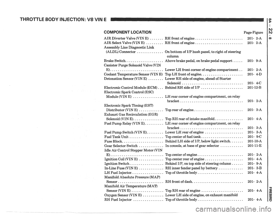
THROTTLE BODY INJECTION: V8 VIN E
COMPONENT LOCATION Page-Figure
AIR Diverter Valve (VIN E)
....... RH front of engine .........................
AIR Select Valve (VIN E) ......... RH front of engine .........................
Assembly Line Diagnostic Link
(ALDL) Connector
.............. On bottom of IIP hush panel, to right of steering
column
Brake Switch.
................... Above brake pedal, on brake pedal support .....
Canister Purge Solenoid Valve (VIN
E)
............................ Lower LH front corner of engine compartment ..
Coolant Temperature Sensor (VIN E) Top LH front of engine. .....................
Detonation Sensor (VIN E) ........ Lower RK side of engine, ahead of Starter
Solenoid
................................
Electronic Control Module (ECM) ... Behind RH side of IIP ......................
Electronic Spark Control (ESC)
Module (VIN E)
................ LH rear corner of engine compartment, on relay
................................. bracket
Electronic Spark Timing (EST)
Distributor (VIN E)
............. Top rear of engine. .........................
Exhaust Gas Recirculation (EGR)
Solenoid (VIN E).
............... Top RH rear of intake manifold. ..............
Fuel Pump Relay (VIN E). ......... LH rear corner of engine compartment, on relay
................................. bracket
Fuel Pump Switch (VIN E).
........ Lower LH rear of engine ....................
Fuel Tank Unit .................. Top center of fuel tank. .....................
Fuse Block. ..................... Behind LH side of IIP, below light switch. ......
Gear Selector Switch ............. In console, at base of gear selector ............
Idle Air Control Stepper Motor (VIN
E)
............................ Topcenterofengine ........................
Ignition Coil (VIN E) ............. Top center rear of engine ....................
Ignition Switch. ................. Behind IIP, on top side of steering column ......
In-Line Fuse (VIN E) ............. RW inner fender panel by battery .............
LW Fuel Injector. ................ Top of throttle body. .......................
Manifold Absolute Pressure (MAP)
Sensor
........................ RH front of dash. ..........................
Manifold Air Temperature (MAT)
Sensor (VIN
E) ................. Top RK rear of engine ......................
Oxygen Sensor (VIN E) ........... Lower LH side of engine, on exhaust manifold
RH Fuel Injector
................ Top of throttle body. .......................
Page 1289 of 1825
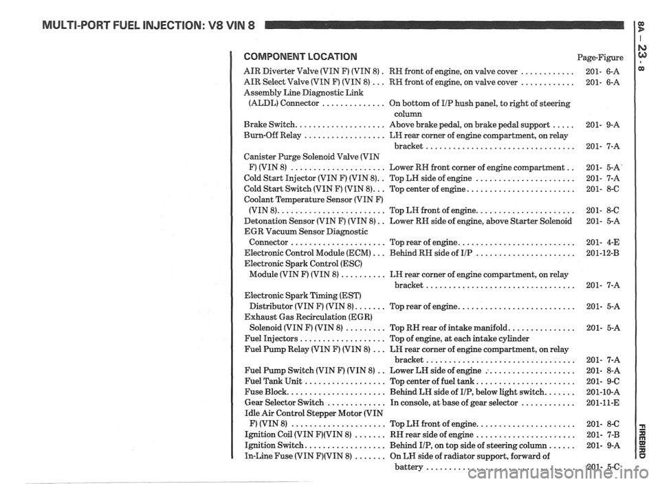
MULTI-PORT FUEL INJECTION: V8 VIN 8 It
COMPONENT LOCATION Page-Figure
. ............ AIR Diverter Valve (VIN F) (VIN 8)
RN front of engine. on valve cover 201- 6-A
............ AIR Select Valve (VIN F) (VIN 8) ... RW front of engine. on valve cover 201- 6-A
Assembly Line Diagnostic Link
(ALDL) Connector
.............. On bottom of I/P hush panel. to right of steering
column
..... Brake Switch .................... Above brake pedal. on brake pedal support 201- 9-A
Burn-Off Relay
.................. LH rear corner of engine compartment. on relay
bracket
................................. 201- 7-A
Canister Purge Solenoid Valve (VIN
.. F) (VIN 8) ..................... Lower RH front corner of engine compartment 201- 5-A'
.. ...................... Cold Start Injector (VIN F) (VIN 8) Top LH side of engine 201- 7-A
........................ Cold Start Switch (VIN F) (VIN 8) ... Top center of engine 201- 8-6
Coolant Temperature Sensor (VIN F)
...................... (VIN 8) ........................ Top LN front of engine 201- 8-C
Detonation Sensor (VIN F) (VIN 8)
. . Lower RN side of engine. above Starter Solenoid 201- 5-A
EGR Vacuum Sensor Diagnostic
.......................... Connector ..................... Top rear of engine 201- 4-E
...................... Electronic Control Module (ECM) ... Behind RH side of IIP 201-12-B
Electronic Spark Control (ESC)
Module (VIN F) (VIN 8)
.......... LH rear corner of engine compartment. on relay
bracket
................................. 201- 7-A
Electronic Spark Timing (EST)
.......................... Distributor (VIN F) (VIN 8) ....... Top rear of engine 201- 5-A
Exhaust Gas Recirculation (EGR)
............... Solenoid (VIN F) (VIN 8) ......... Top RN rear of intake manifold 201- 5-A
Fuel Injectors
................... Top of engine. at each intake cylinder
Fuel Pump Relay (VIN F) (VIN 8)
... LH rear corner of engine compartment. on relay
bracket
................................. 201- 7-A
.. ................... Fuel Pump Switch (VIN F) (VIN 8)
Lower LH side of engine : 201- 8-A
...................... Fuel Tank Unit .................. Top center of fuel tank 201- 9-C
....... Fuse Block ...................... Behind LH side of IIP. below light switch 201-10-A
............ Gear Selector Switch ............. In console. at base of gear selector 201-11-E
Idle Air Control Stepper Motor (VIN
...................... F) (VIN 8) ..................... Top LN front of engine 201- 8-C
...................... Ignition Coil (VIN F)(VIN 8) ....... RH rear side of engine 201- 7-B
...... Ignition Switch .................. Behind IIP. on top side of steering column 201- 9-A
In-Line Fuse (VIN F)(VIN 8) ....... On LH side of radiator support. forward of
battery
................................. 201- 5-C
Page 1403 of 1825
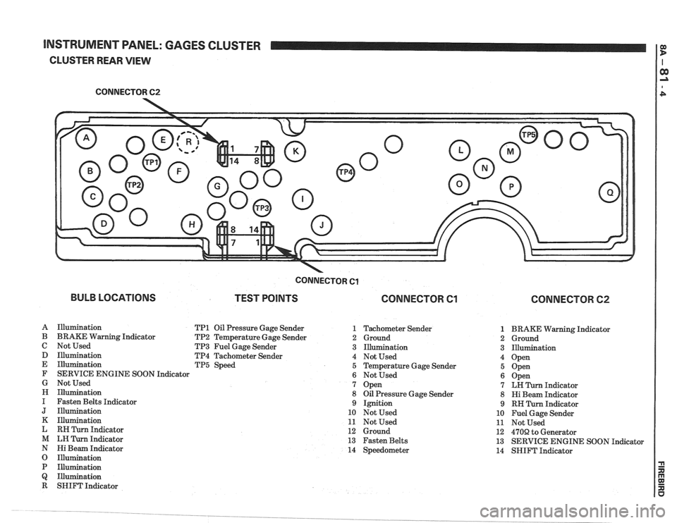
INSTRUMENT PANEL: GAGES CLUSTER I e
CLUSTER REAR VIEW
CONNECTOR 62
-
BULB LOCATIONS
CONNECTOR Cl
TEST POINTS CONNECTOR Cl
A Illumination TP1 Oil Pressure Gage Sender 1
B BRAKE Warning Indicator TP2 Temperature Gage Sender 2
C Not Used TP3 Fuel Gage Sender 3
D Illumination TP4 Tachometer Sender 4
E Illumination TP5 Speed 5
F SERVICE ENGINE SOON Indicator
6
G Not Used 7
H Illumination 8
I Fasten Belts Indicator 9
J Illumination 10
K Illumination 11
L RH Turn Indicator 12
M LH Turn Indicator 13
N Hi Beam Indicator 14
O Illumination
P Illumination
Q Illumination
R SHIFT Indicator Tachometer Sender
Ground
Illumination
Not Used
Temperature Gage Sender
Not Used
Open
Oil Pressure Gage Sender
Ignition
Not Used
Not Used
Ground
Fasten Belts
Speedometer
CONNECTOR 62
1 BRAKE Warning Indicator
2 Ground
3 Illumination
4 Open
5 Open
6 Open
7 LH Turn Indicator
8 Hi Beam Indicator
9 RH Turn Indicator
10 Fuel Gage Sender
11 Not Used
12
470R to Generator
13 SERVICE ENGINE SOON Indicator
14 SHIFT Indicator
Page 1404 of 1825
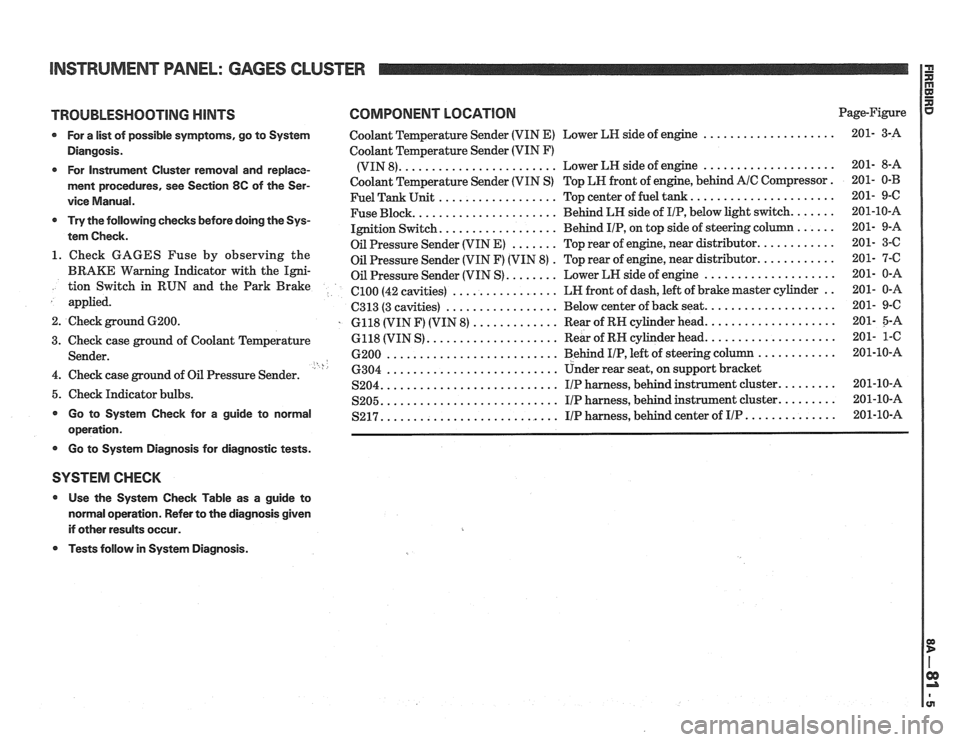
INSTRUMENT PANEL: GAGES CLUSTER
TROUBLESHOOTING HINTS COMPONENT LOCATION Page-Figure
* For a list of possible symptoms, go to System Coolant Temperature Sender (VIN E) Lower LH side of engine ....................
Diangosis. Coolant Temperature Sender (VIN F)
....................... .................... * For Instrument Cluster removal and replace- (VIN 8). Lower
LH side of engine
ment procedures, see Section 8C of the Ser- Coolant Temperature Sender (VIN S) Top LN front of engine, behind A/C Compressor.
.................. ..................... vice Manual. Fuel Tank Unit Top center of fuel tank.
..................... ...... * Try the following checks before doing the Sys- Fuse Block. Behind
LH side of IIP, below light switch.
................. tem Check. Ignition Switch. Behind IIP, on
top side of steering co
....... ........... Oil Pressure Sender (VIN E) Top rear of engine, near distributor. 1. Check GAGES Fuse by observing the . ........... Oil Pressure Sender (VIN F) (VIN 8) Top
rear of engine, near distributor.
BRAKE Warning Indicator with the Igni- Oil Pressure Sender (VIN S) ........ Lower LN side of engine .................... tion Switch in RUN and the Park Brake ................ .. el00 (42 cavities) LN
front of dash, left of brake master cylinder
applied.
................. C313 (3 cavities) Below
center of back seat. ...................
2. Check ground 6200. . 6118 (VIN F) (VIN 8) ............. Rear of RN cylinder head. ...................
.................... ................... 3. Check case ground of Coolant Temperature 6118
(VIN S) Rear
of RH cylinder head.
.......................... ............ Sender. 6200 Behind I/P, left of steering column ' h .......................... 4. Check case ground of Oil Pressure Sender. 6304 Under rear seat,
on support bracket
.......................... S204. IIP harness, behind instrument cluster. ........ 5. Check Indicator bulbs. .......................... ........ S205. I/P harness, behind instrument cluster. * Go to System Check for a guide to normal .......................... S217. I/P harness, behind center of IIP .............. operation.
* Go to Systern Diagnosis for diagnostic tests.
SYSTEM CHECK
* Use the System Check Table as a guide to
normal operation. Refer to the diagnosis given
if other results occur.
* Tests follow in System Diagnosis.