1988 PONTIAC FIERO engine oil
[x] Cancel search: engine oilPage 410 of 1825
V-8 ENGINE 6A3-31
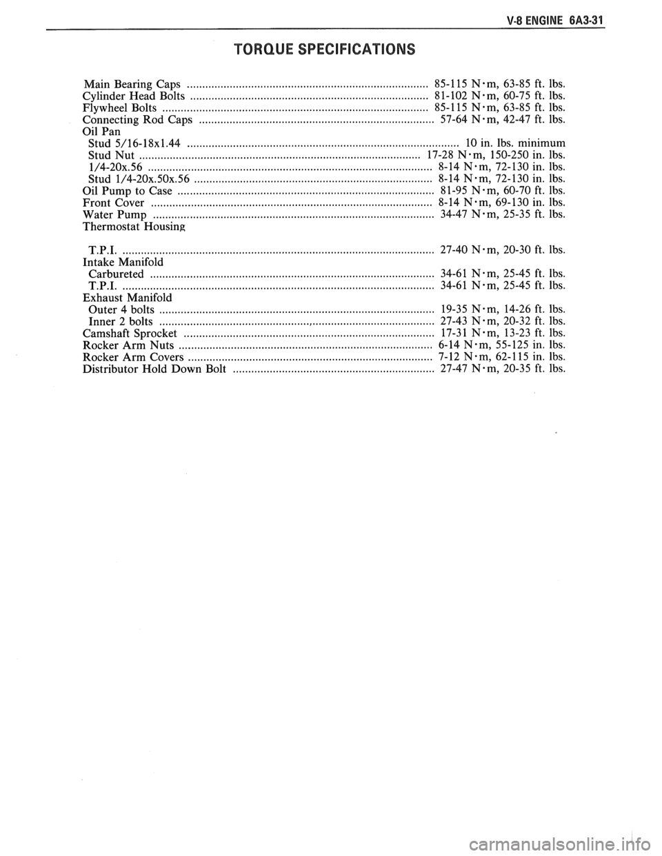
TORQUE SPECIFIGAUONS
Main Bearing Caps ............................................................................ 85-1 15 N-m, 63-85 ft. lbs.
Cylinder Head Bolts
.............................................................................. 81-102 N-m, 60-75 ft. lbs.
Flywheel Bolts
....................................................................................... 85-1 15 Nem, 63-85 ft. lbs.
........................................................................... Connecting Rod Caps 57-64 N-m, 42-47 ft. lbs.
Oil Pan
Stud
5/16-18~1.44 ....................................................................................... 10 in. lbs. minimum
Stud Nut
............................................................................................ 17-28 N-m, 150-250 in. lbs.
1/4-20x.56 ........................................................................................... 8-14 N-m, 72-130 in. lbs.
Stud
1/4-20x.50x.56 ............................................................................ 8-14 N.m, 72-130 in. lbs.
Oil Pump to Case
.................................................................................... 8 1-95 N . m, 60-70 ft. lbs.
Front Cover
............................................................................................ 8-14 N-m, 69-130 in. lbs.
Water Pump
........................................................................................... 34-47 N-m, 25-35 ft. lbs.
Thermostat Housing
T.P.I.
...................................................................................................... 27-40 N-m, 20-30 ft. Ibs.
Intake Manifold
Carbureted
............................................................................................. 34-61 N.m, 25-45 ft. Ibs.
T.P.I.
...................................................................................................... 34-61 N-m, 25-45 ft. Ibs.
Exhaust Manifold
Outer 4 bolts
.......................................................................................... 19-35 N-m, 14-26 ft. lbs.
Inner 2 bolts
........................................................................................ 27-43 N.m, 20-32 ft. Ibs.
Camshaft Sprocket
.................................................................................. 17-3 1 N-m, 13-23 ft. lbs.
Rocker Arm Nuts
................................................................................. 6-14 N-m, 55-125 in. Ibs.
Rocker Arm Covers
............................................................................. 7-12 N- m, 62- 11 5 in. Ibs.
Distributor Hold Down Bolt
.................................................................. 27-47 N-m, 20-35 ft. lbs.
Page 412 of 1825
ENGINE COOLING 6B-1
SECTION 6B
NE COOL
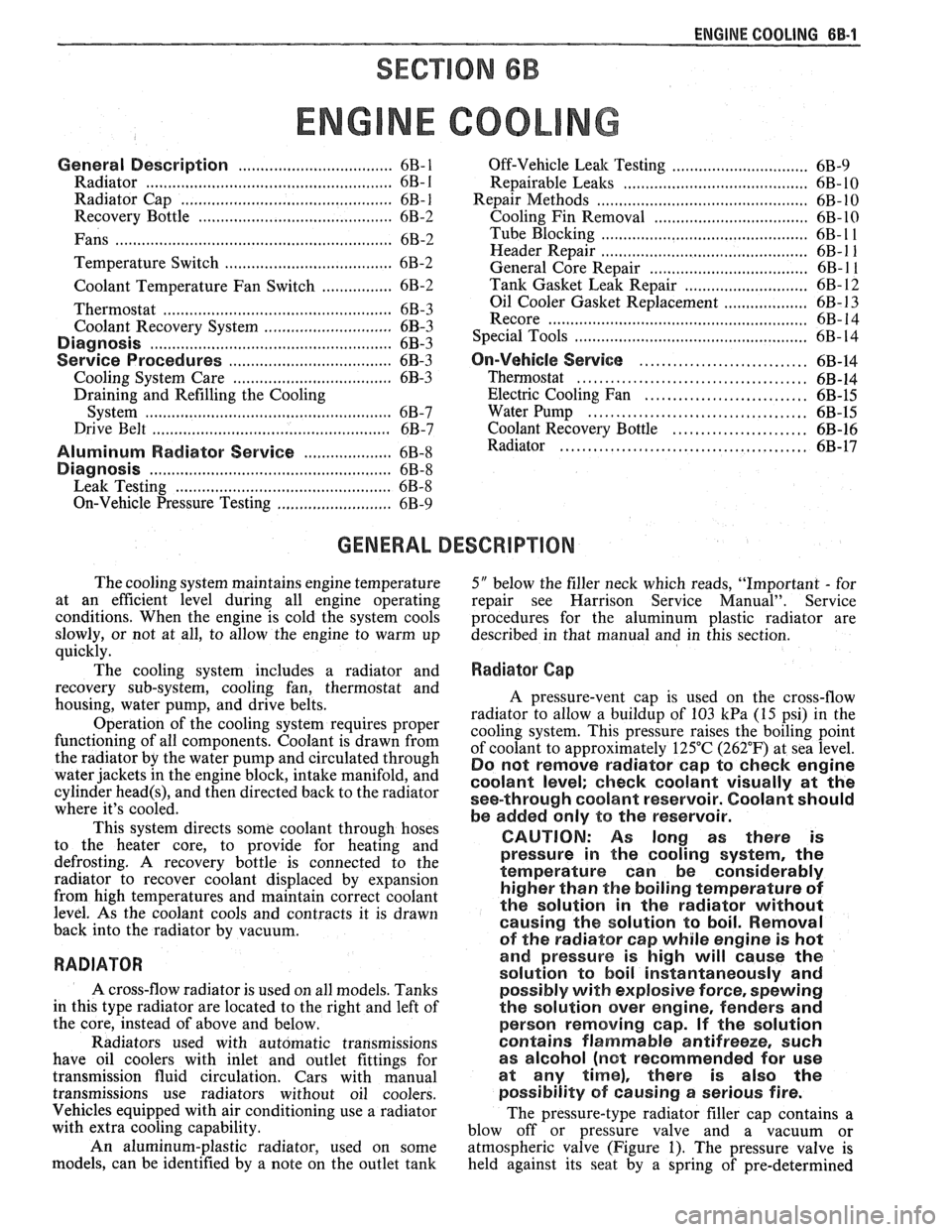
General Description ................................ 6B- 1 Off-Vehicle Leak Testing ............................... 6B-9
Radiator
...................................................... 6B- 1 Repairable Leaks ........................ ... .......... 6B- 10
Radiator Cap
......................... .. ............... 6B- 1 Repair Methods ................................................ 6B- 10
Recovery Bottle ......................................... 6B-2 Cooling Fin Removal ................................ 6B- 10 - ............................................. Fans ............................................................... 6B-2 Tube Blocking 6B- 1 1 ............ Header Repair ....................... .... 6B- 1 1 Temperature Switch ..................................... 6B-2 General Core Repair 6B- 1 1 ....................................
........................... Coolant Temperature Fan Switch ................ 6B-2 Tank
Gasket ~eik Repair 6B- 12
................... Thermostat .. 6B-3 Oil
Cooler Gasket Replacement
6B- 13 ............... ................................
...........................................................
Coolant Recovery System 6B-3 Recore 6B- 14 ............................. Special Tools ..................................................... 6B- 14 Diagnosis ..................................................... 6B-3
.............................. ..................................... Service Procedures 6B-3 On-Vehicle Service 6B-14
Cooling System Care
............................... 6B-3 Thermostat ....................................... 6B-14
Draining and Refilling the Cooling Electric Cooling Fan ............................. 6B-15
System
................................................... 6B-7 Water Pump .................... .... ......... 6B-15
Drive Belt
...................... .. .......................... 6B-7 Coolant Recovery Bottle ........................ 6B-16
.......................................... Aluminum Radiator Service .................... 6B-8 Radiator 6B-17
Diagnosis .................................................... 6B-8
Leak Testing
.............................................. 6B-8
On-Vehicle Pressure Testing
...................... .... 6B-9
GENERAL DESCRIPnIBN
The cooling system maintains engine temperature
5" below the filler neck which reads, "Important - for
at an efficient level during all engine operating repair see Harrison Service Manual". Service
conditions. When the engine is cold the system cools procedures for the aluminum plastic radiator are
slowly, or not at all, to allow the engine to warm up described in that manual and in this section.
quickly.
The cooling system includes a radiator and
Radiator Cap
recovery sub-system, cooling fan, thermostat and
housing, water pump, and drive belts.
Operation of the cooling system requires proper
functioning of all components. Coolant is drawn from
the radiator by the water pump and circulated through
water jackets in the engine block, intake manifold, and
cylinder
head(s), and then directed back to the radiator
where it's cooled.
This system directs some coolant through hoses
to the heater core, to provide for heating and
defrosting. A recovery bottle is connected to the
radiator to recover coolant displaced by expansion
from high temperatures and maintain correct coolant
level. As the coolant cools and contracts it is drawn
back into the radiator by vacuum.
RADIATOR
A cross-flow radiator is used on all models. Tanks
in this type radiator are located to the right and left of
the core, instead of above and below.
Radiators used with automatic transmissions
have oil coolers with inlet and outlet fittings for
transmission fluid circulation. Cars with manual
transmissions use radiators without oil coolers.
Vehicles equipped with air conditioning use a radiator
with extra cooling capability.
An aluminum-plastic radiator, used on some
models, can be identified by a note on the outlet tank A pressure-vent
cap is used on the cross-flow
radiator to allow a buildup of
103 kPa (15 psi) in the
cooling system. This pressure raises the boiling point
of coolant to approximately 125°C (262°F) at sea level.
Do not remove radiator cap to check engine
coolant level; check coolant visually at the
see-through coolant reservoir. Coolant should
be added only
to the reservoir.
CAUTION: As long as there
is
pressure in the cooling system, the
temperature can be considerably
higher than the boiling temperature
of
the solution in the radiator without
causing the solution to boil. Removal
of the radiator cap while engine is hot
and pressure is high will cause
the
solution to boil instantaneously and
possibly with explosive
force, spewing
the solution over engine, fenders and
person removing cap. If the solution
contains flammable antifreeze, such
as alcohol (not recommended for use
at any time), there is also the
possibility
of causing a serious fire.
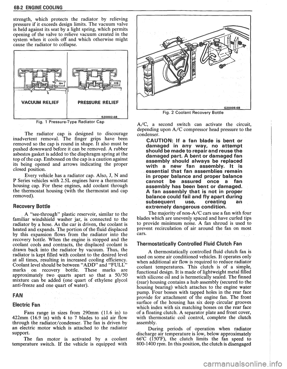
The pressure-type radiator filler cap contains a
blow off or pressure valve and a vacuum or
atmospheric valve (Figure
1). The pressure valve is
held against its seat by a spring of pre-determined
Page 413 of 1825
BB-2 ENGINE COOLING
strength, which protects the radiator by relieving
pressure if it exceeds design limits. The vacuum valve
is held against its seat by a light spring, which permits
opening of the valve to relieve vacuum created in the
system when it cools off and which otherwise might
cause the radiator to collapse.
VACUUM RELIEF PRESSURE RELIEF
Fig. 1 Pressure-Type Radiator Cap
The radiator cap is designed to discourage
inadvertent removal. The finger grips have been
removed so the cap is round in shape. It also must be
pushed downward before it can be removed. A rubber
asbestos gasket is added to the diaphragm spring at the
top of the cap. Embossed on the cap is a caution against
its being opened and arrows indicating the proper
closed position.
Every vehicle has a radiator cap. Also,
J, N and
P Series vehicles with 2.5L engines have a thermostat
housing cap. For these engines, add coolant through
the thermostat housing (with the thermostat and cap
removed).
Recovery Bottle
A "see-through" plastic reservoir, similar to the
familiar windshield washer jar, is connected to the
radiator by a hose. As the car is driven, the coolant is
heated and expands. The portion of the fluid displaced
by this expansion flows from the radiator into the
recovery bottle. When the engine is stopped and the
coolant cools and contracts, the displaced coolant is
drawn back into the radiator by vacuum. Thus, the
radiator is kept filled with coolant to the desired level
at all times, resulting in increased cooling efficiency.
Coolant level should be between "ADD" and
"FULL"
marks on recovery bottle. These marks are
approximately two quarts apart so that a
50/50
mixture can be added (one quart of ethylene glycol
anti-freeze and one quart of water).
FAN
Electric Fan
Fans range in sizes from 290mm (11.6 in) to
422mm (16.9 in) with 4 to 7 blades to aid air flow
through the
radiator/condenser. The fan is driven by
an electric motor which is attached to the radiator
support.
The fan motor is activated by a coolant
temperature switch. If the vehicle is equipped with
Fig. 2 Coolant Recovery Bottle
A/C, a second switch can activate the circuit,
depending upon
A/C compressor head pressure to the
condenser.
CAUTION: If a fan blade is bent or
damaged in any way, no attempt
should be made to repair and reuse the
damaged part.
A bent or damaged fan
assembly should always be replaced
with a new fan assembly. It is
essential that fan assemblies remain
in proper balance and proper balance
cannot be assured once a fan
assembly has been bent or damaged.
A fan assembly that is not in proper
balance could fail and fly apart during
subsequent use, creating an
extremely dangerous condition.
The majority of non-A/C cars use a fan with four
blades which are unevenly spaced and have curled tips
to provide minimum noise.
A fan shroud is used to
prevent recirculation of air around the fan on most
cars.
Thermostatically Controlled Fluid Clutch Fan
A thermostatically controlled fluid clutch fan is
used on some air conditioned vehicles. It operates only
when additional air flow is required to reduce radiator
coolant temperatures. This clutch is of a simple,
functional design. It is made of lightweight metal filled
with silicone oil and is hermetically sealed. The finned
(rear) housing contains a hub assembly (secured to the
housing bearing) which attaches to the engine water
pump. Four bosses with tapped holes in the rear face
provide for attachment of the engine fan. The front
surface of the housing has six deep circular grooves
which index with six matching bosses on the rear face
of a floating clutch. A separator plate and front cover,
with thermostatic coil control, complete the clutch
assembly.
During periods of operation when radiator
discharge air temperature is low, below approximately
66°C (150°F), the clutch limits the fan speed to
800- 1400 rpm. In this position, the clutch is disengaged
Page 414 of 1825
ENGINE COOLING 88.3
since a small oil pump driven by the separator plate
forces the silicone oil into a reservoir between the
separator plate and the front cover assembly. In this
position, the passage from this cavity to the clutch area
is closed by a slide valve. As operating conditions
produce a high radiator air temperature discharge,
above approximately 66°C
(150"F), the temperature
sensitive bi-metal coil tightens to move the slide valve
(attached to the coil) which opens a port in the
separator plate. This allows a flow of silicone oil into
the clutch chamber to engage the clutch, providing a
maximum fan speed of approximately 2200 rpm. The
clutch coil is calibrated so that, with a road load at an
ambient temperature of approximately 32°C
(90T), the
clutch is just at a point of shift between high and low
fan speed. No attempt should be made to disturb the
calibration of the engine clutch fan assembly as each
assembly is individually calibrated at the time of
manufacture. Under certain temperature conditions
there is a lateral movement at the fan tip which should
not be considered as a hub or bearing failure. This
condition is a design feature of the clutch assembly
which allows up to approximately
1/4" lateral
movement measured at the fan tip.
Testing a clutch fan by holding the small hub
with one hand and rotating the aluminum housing in
a
clockwise/counter-clockwise motion will cause the
clutch to freewheel, which is a normal condition when
operated in this manner. This should not be considered
a test by which replacement is determined.
Temperature Switch
This switch activates a warning lamp in the
instrument cluster if the engine overheats. With
optional instrumentation, a temperature gage replaces
the warning lamp and the temperature switch is
replaced with a transducer. See Section
8A for
Temperature Switch location and diagnosis.
Coolant Temperature Fan Switch
This switch regulates voltage to the coolant fan
relay, which operates the fan whenever the engine
coolant temperature exceeds 230"
F (110" C). For
location and diagnosis see Section 8A for Coolant
Temperature Fan Switch.
Thermostat
A pellet-type thermostat is used in the coolant
outlet passage to control the flow of engine coolant, to
provide fast engine warm-up and to regulate coolant
temperatures.
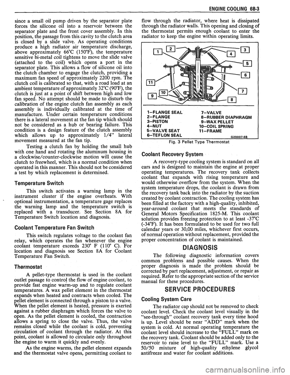
A wax pellet element in the thermostat
expands when heated and contracts when cooled. The
pellet element is connected through a piston to a valve.
When the pellet element is heated, pressure is exerted
against a rubber diaphragm which forces the valve to
open. As the pellet element is cooled, the contraction
allows a spring to close the valve. Thus, the valve
remains closed while the coolant is cold, preventing
circulation of coolant through the radiator. At this
point, coolant is allowed to circulate only throughout
the engine to warm it quickly and evenly.
As the engine warms, the pellet element expands
and the thermostat valve opens, permitting coolant to flow
through the radiator, where heat is dissipated
through the radiator walls. This opening and closing of
the thermostat permits enough coolant to enter the
radiator to keep the engine within operating limits.
Fig. 3 Pellet Type Thermostat
Coolant Recovery System
A recovery-type cooling system is standard on all
cars and is designed to maintain the engine at proper
operating temperatures. The recovery tank collects
coolant that expands with rising temperature and
would otherwise overflow from the system. When the
system temperature drops, the coolant is drawn from
the recovery tank back into the radiator by the suction
created by coolant contraction. The cooling system has
been filled at the factory with a high-quality, inhibited,
year-around coolant that meets the standards of
General Motors Specification 1825-M. This coolant
solution provides freezing protection to at least -37°C
(-34°F). It has been formulated to be used for two full
calendar years or
30,OO miles, whichever first occurs,
of normal operation without replacement, provided the
proper concentration of coolant is maintained.
DIAGNOSIS
The following diagnostic information covers
common problems and possible causes. When the
proper diagnosis is made the problem should be
corrected by part replacement, adjustment, or repair as
required. Refer to the appropriate section of the service
manual for these procedures.
SERVICE PROCEDURES
Cooling System Care
The radiator cap should not be removed to check
coolant level. Check the coolant level visually in the
"see-through" coolant recovery tank every time hood
is up. Level should be near "ADD" mark when the
system is cold. At normal operating temperature the
coolant level should increase to the "FULL" mark on
the recovery tank. Coolant should be added only to the
reservoir to raise level to the "FULL" mark. Use a
50/50 mixture of high-quality ethylene glycol
antifreeze and water for coolant additions.
Page 415 of 1825
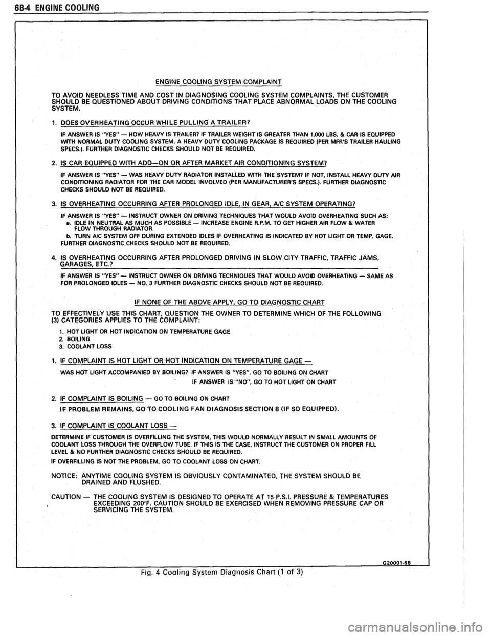
BB.4 ENGINE COOLING
ENGINE COOLING SYSTEM COMPLAINT
TO AVOID NEEDLESS
TIME AND COST IN DIAGNOSING COOLING SYSTEM COMPLAINTS, THE CUSTOMER
SHOULD BE QUESTIONED ABOUT DRIVING CONDITIONS THAT PLACE ABNORMAL LOADS ON THE COOLING
SYSTEM.
1. DOES OVERHEATING OCCUR WHILE PULLING A TRAILER?
IF ANSWER IS "YES'- HOW HEAVY IS TRAILER? IF TRAILER WEIGHT IS GREATER THAN 1,000 LBS. & CAR IS EQUIPPED
WITH NORMAL DUTY COOLING SYSTEM, A HEAVY DUTY COOLING PACKAGE IS REQUIRED (PER MFR'S TRAILER HAULING
SPECS.). FURTHER DIAGNOSTIC CHECKS SHOULD NOT BE REQUIRED.
2. IS CAR EQUIPPED WlTH ADD-ON OR AFTER MARKET AIR CONDITIONING SYSTEM?
IF ANSWER IS "YES"- WAS HEAVY DUTY RADIATOR INSTALLED WITH THE SYSTEM? IF NOT, INSTALL HEAVY DUTY AIR
CONDITIONING RADIATOR FOR THE CAR MODEL INVOLVED (PER MANUFACTURER'S SPECS.). FURTHER DlAGNOSTlC
CHECKS SHOULD NOT BE REQUIRED.
3. IS OVERHEATING OCCURRING AFTER PROLONGED IDLE, IN GEAR, AIC SYSTEM OPERATING?
IF ANSWER IS "YES - INSTRUCT OWNER ON DRIVING TECHNIQUES THAT WOULD AVOID OVERHEATING SUCH AS: a, IDLE IN NEUTRAL AS MUCH AS POSSIBLE - INCREASE ENGINE R.P.M. TO GET HIGHER AIR FLOW & WATER
FLOW THROUGH RADIATOR.
b. TURN A/C SYSTEM OFF DURING EXTENDED IDLES IF OVERHEATING IS INDICATED BY HOT LIGHT OR TEMP. GAGE.
FURTHER DIAGNOSTIC CHECKS SHOULD NOT BE REQUIRED.
4. IS OVERHEATING OCCURRING AFTER PROLONGED DRIVING IN SLOW CITY TRAFFIC, TRAFFIC JAMS,
GARAGES, ETC.?
IF ANSWER IS "YES - INSTRUCT OWNER ON DRIVING TECHNIQUES THAT WOULD AVOID OVERHEATING - SAME AS
FOR PROLONGED IDLES - NO. 3 FURTHER DIAGNOSTIC CHECKS SHOULD NOT BE REQUIRED.
IF NONE OF THE ABOVE APPLY, GO TO DIAGNOSTIC CHART
TO EFFECTIVELY USE THlS CHART, QUESTION THE OWNER TO DETERMINE WHICH OF THE FOLLOWING
(3) CATEGORIES APPLIES TO THE COMPLAINT:
1. HOT LlGHT OR HOT INDICATION ON TEMPERATURE GAGE 2. BOILING 3. COOLANT LOSS
1. IF COMPLAINT IS HOT LlGHT OR HOT INDICATION ON TEMPERATURE GAGE -
WAS HOT LlGHT ACCOMPANIED BY BOILING? IF ANSWER IS "YES", GO TO BOILING ON CHART
IF ANSWER IS "NO, GO TO HOT LlGHT ON CHART
2. IF COMPLAINT IS BOILING - GO TO BOILING ON CHART
IF PROBLEM REMAINS, GO TO COOLING
FAN DIAGNOSIS SECTION 8 (IF SO EQUIPPED).
I 3. IF COMPLAINT IS COOLANT LOSS -
DETERMINE IF CUSTOMER IS OVERFILLING THE SYSTEM, THlS WOULD NORMALLY RESULT IN SMALL AMOUNTS OF
I COOLANT LOSS THROUGH THE OVERFLOW TUBE. IF THlS IS THE CASE, INSTRUCT THE CUSTOMER ON PROPER FILL LEVEL & NO FURTHER DIAGNOSTIC CHECKS SHOULD BE REQUIRED.
I IF OVERFILLING IS NOT THE PROBLEM, GO TO COOLANT LOSS ON CHART.
NOTICE:
ANYTIME COOLING SYSTEM IS OBVIOUSLY CONTAMINATED, THE SYSTEM SHOULD BE
DRAINED AND FLUSHED.
1 CAUTION - THE COOLING SYSTEM IS DESIGNED TO OPERATE AT 15 P.S.I. PRESSURE & TEMPERATURES
EXCEEDING 200°F. CAUTION SHOULD BE EXERCISED WHEN REMOVING PRESSURE CAP OR
I SERVICING THE SYSTEM.
Fig. 4 Cooling System Diagnosis Chart (I of 3)
Page 416 of 1825
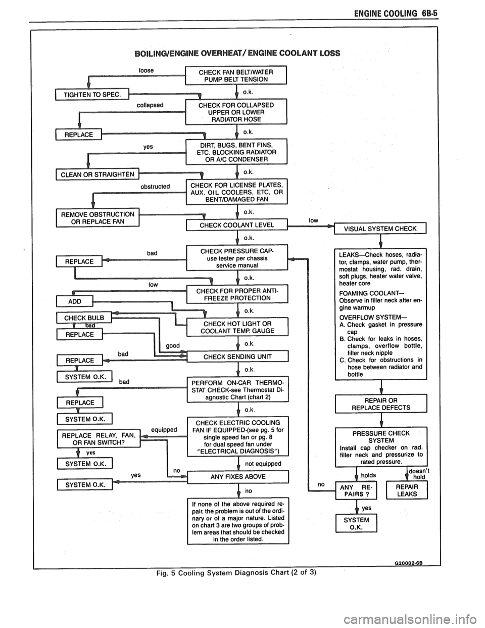
ENGINE COOLING 6B-5
BOILINGIENGINE OVERHEAT/ ENGINE COOLANT LOSS
FOAMING COOLANT- Observe in filler neck after en-
for leaks in hoses. , overflow bottle,
for obstructions in
on chart
3 are two groups of prob-
Page 417 of 1825
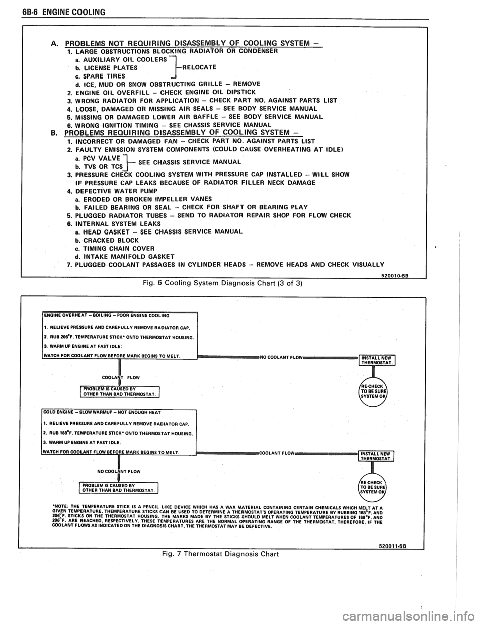
6B-8 ENGINE COOLING
PROBLEMS NOT REQUIRING DISASSEMBLY OF COOLING SYSTEM - 1. LARGE OBSTRUCTIONS BLOCKING RADIATOR OR CONDENSER
a. AUXILIARY OIL COOLERS
b. LICENSE PLATES R ELOCATE
c. SPARE TIRES
d. ICE, MUD OR SNOW OBSTRUCTING GRILLE - REMOVE
2. ENGINE OIL OVERFILL - CHECK ENGINE OIL DIPSTICK
3. WRONG RADIATOR FOR
APPLICATION - CHECK PART NO. AGAINST PARTS LlST
4. LOOSE, DAMAGED OR MISSING AIR SEALS - SEE BODY SERVICE MANUAL
5. MISSING OR DAMAGED LOWER AIR BAFFLE - SEE BODY SERVICE MANUAL
6. WRONG IGNITION TIMING - SEE CHASSIS SERVICE MANUAL PROBLEMS REQUIRING DISASSEMBLY OF COOLING SYSTEM -
1. INCORRECT OR DAMAGED FAN - CHECK PART NO. AGAINST PARTS LlST
2. FAULTY EMISSION SYSTEM COMPONENTS (COULD CAUSE OVERHEATING AT IDLE)
; SEE CHASSIS SERVICE MANUAL
3. PRESSURE CHECK COOLING SYSTEM WITH PRESSURE CAP INSTALLED - WILL SHOW
IF PRESSURE CAP LEAKS BECAUSE OF RADIATOR FILLER NECK DAMAGE
4. DEFECTIVE WATER PUMP
a. ERODED OR BROKEN IMPELLER VANES
b. FAILED BEARING OR SEAL - CHECK FOR SHAFT OR BEARING PLAY
5. PLUGGED RADIATOR TUBES - SEND TO RADIATOR REPAIR SHOP FOR FLOW CHECK
6. INTERNAL SYSTEM LEAKS
B. HEAD GASKET - SEE CHASSIS SERVICE MANUAL
b. CRACKED BLOCK
c. TIMING CHAIN COVER
d. INTAKE MANIFOLD GASKET
7. PLUGGED COOLANT PASSAGES IN CYLINDER HEADS - REMOVE HEADS AND CHECK VISUALLY
Fig. 6 Cooling System Diagnosis Chart (3 of 3)
1. RELIEVE PRESSURE AND CAREFULLY REMOVE RADIATOR CAP.
2. RUB W'F. TEMPERATURE STICK* ONTO THERMOSTAT MOUSING.
3. WARM UP ENGINE AT FAST IDLE:
WATCH FOR COOLANT FLOW BEFORE MAR
NO COOLANT FLOW INSTALL NEW
THERMOSTAT.
COLD ENGINE -SLOW WARMUP -NOT ENOUGH HEAT
1. RELIEVE PRESSURE AND CAREFULLY REMOVE RADIATOR CAP.
2. RUB 188'~. TEMPERATURE STICK' ONTO THERMOSTAT HOUSING.
3. WARM UP ENGINE AT FAST IDLE.
COOLANT FLOW
- 'NOTE: THE TEMPERATURE STICK IS A PENCIL LIKE DEVICE WHICH HAS A WAX MATERIAL CONTAINING CERTAIN CHEMICALS WHICH MELT AT A GIVEN TEMPERATURE THEWERATURE STICKS CAN BE USED TO DETERMINE A THERMOSTAT'S OPERATING TEMPERATURE BY RUBBING laB°F AN0 =OF. STICKS ON THE THERMOSTAT HOUSING. THE MARKS MADE BY THE STICKS SHOULD MELT WHEN COOLANT TEMPERATURES OF IWOF'AND W'F. ARE REACHED, RESPECTIVELY. THESE TEMPERATURES ARE THE NORMAL WERATING RANGE OF THE THERMOSTAT. THEREFORE, ~i WE COOLANT FLOWS AS INDICATED ON THE DIAGNOSIS CHART. THE THERMOSTAT MAY BE DEFECTIVE.
Fig. 7 Thermostat Diagnosis Chart
Page 418 of 1825
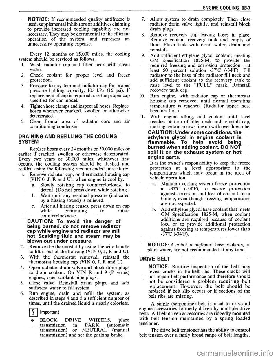
ENGINE COOLING BB-7
NOTICE: If recommended quality antifreeze is
used, supplemental inhibitors or additives claiming
to provide increased cooling capability are not
necessary. They may be detrimental to the efficient
operation of the system, and represent an
unnecessary operating expense.
Every 12 months or 15,000 miles, the cooling
system should be serviced as follows;
1. Wash radiator cap and filler neck with clean
water.
2. Check coolant for proper level and freeze
protection.
3. Pressure test system and radiator cap for proper
pressure holding capacity, 103
kPa (15 psi). If
replacement of cap is required, use the proper cap
specified for car model.
4. Tighten hose clamps and inspect all hoses. Replace
hoses whenever cracked, swollen or otherwise
deteriorated.
5. Clean frontal area of radiator core and air
conditioning condenser.
DRAINING AND REFILLING THE COOLING
SYSTEM
Replace hoses every 24 months or 30,000 miles or
earlier if cracked, swollen or otherwise deteriorated.
Every two years or 30,000 miles, whichever first
occurs, the cooling system should be flushed and
refilled using the following recommended procedure:
1. Remove radiator cap, or thermostat housing cap
(VIN
0, J, R and U), when engine is cool by:
a. Slowly
rotating cap counterclockwise to
detent. (Do not press down while rotating.)
b. Wait until any
residual pressure (indicated
by a hissing sound) is relieved.
c. After all hissing ceases, press down on cap
while continuing to rotate
counterclockwise.
CAUTION: To avoid the danger of
being burned, do not remove radiator
cap while engine and radiator are still
hot. Scalding fluid and steam may be
blown out under pressure.
2. Remove the thermostat by using the wire handle
to lift it out of the housing (VIN
0, J, R and U).
3. With the thermostat removed, reinstall the
thermostat housing cap (VIN
0, J, R and U).
4. Open radiator drain valve and block drain plugs
to drain coolant. On VIN R and
9 (P series)
engines, open coolant pipe plugs.
5. Close valve. Reinstall drain plugs, and add
sufficient water to fill system.
6. Run engine, drain and refill the system, as
described in steps
4 and 5 a sufficient number of
times, until the drained liquid is nearly colorless.
Important
BLOCK DRIVE WHEELS, place
transmission in PARK (automatic
transmission) or NEUTRAL (manual
transmission) and set the parking brake. 7.
Allow system to drain completely. Then close
radiator drain valve tightly, and reinstall block
drain plugs.
8. Remove recovery cap leaving hoses in place.
Remove coolant recovery tank and empty of
fluid. Flush tank with clean water, drain and
reinstall.
9. Add sufficient ethylene glycol coolant, meeting
GM specification 1825-M, to provide the
required freezing and corrosion protection
- at
least 50 percent solution -37°C (-34°F). Fill
radiator to the base of the radiator fill neck and
add sufficient coolant to the recovery tank to
raise level to the "FULL" mark. Reinstall
recovery tank cap.
10. Run engine, with radiator cap or thermostat
housing cap removed, until normal operating
temperature is reached. (Radiator upper hose
becomes hot.)
11. With engine idling, add coolant until level
reaches bottom of filler neck and reinstall cap,
making certain arrows line up with overflow tube.
CAUTION: Under some conditions, the
ethylene glycol in engine coolant is
flammable. To help avoid being
burned when adding coolant, DO NOT
spill
it on the exhaust system or hat
engine parts.
It is the owner's responsibility to keep the freeze
protection at a level appropriate to the
temperatures which may occur in the area of
vehicle operation.
a. Maintain
cooling system freeze protection
at
-37°C (-34"F), to ensure protection
against corrosion and loss of coolant from
boiling, even though freezing temperatures
are not expected.
b. Add ethylene glycol base coolant that meets
GM Specification 1825-M, when coolant
additions are required because of coolant
loss, or to provide additional protection
against
freezing at temperatures lower than
-37°C (-34°F).
NOTICE: Alcohol or methanol base coolants, or
plain water, are not recommended at any time.
DRlVE BELT
NOTICE: Routine inspection of the belt may
reveal cracks in the belt ribs. These cracks will
not impair belt performance and therefore should
not be considered a problem requiring belt
replacement. However, the belt should be
replaced if belt slip occurs or if sections of the
belt ribs are missing.
A single (serpentine) belt is used to drive all
engine accessories formerly driven by multiple drive
belts. All belt driven accessories are ridgedly mounted
with belt tension maintained by a spring loaded
tensioner.
The drive belt tensioner has the ability to control
belt tension over a fairly broad range of belt lengths.